Ryobi PLT3043S User manual

OPERATOR'S MANUAL
StringTrimmer
PLT3043S
YournewtrimmerhasbeenengineeredandmanufacturedtoRyobi’shighstandardfordependability,easeofoperation,andoperator
safety.Properly cared for, it will give you years of rugged, trouble-free performance.
Thank you for buying a Ryobi trimmer.
SAVETHIS MANUAL FOR FUTURE REFERENCE
WARNING: To reduce the risk of injury, the user must read and understand the operator’s manual before
using this product.

2
TABLE OF CONTENTS
■■
■■
■Safety...................................................................................................................................................................... 2 - 3
■■
■■
■Symbols .................................................................................................................................................................. 4 - 5
■■
■■
■Technical Data ...............................................................................................................................................................5
■■
■■
■Unpacking .....................................................................................................................................................................6
■■
■■
■Features ........................................................................................................................................................................6
■■
■■
■Assembly ................................................................................................................................................................ 7 - 9
■■
■■
■Operation..............................................................................................................................................................10 - 12
■■
■■
■Maintenance .........................................................................................................................................................13 - 15
■■
■■
■Troubleshooting.....................................................................................................................................................16 - 17
■■
■■
■Safety Directive...........................................................................................................................................................17
■■
■■
■Warranty ......................................................................................................................................................................18
SAFETY
WARNING:
Do not attempt to operate this trimmer until you thoroughly read and completely understand all instructions, safety
rules, etc. contained in this manual. Failure to comply can result in accidents involving fire, electric shock, or
seriouspersonalinjury.Saveoperator'smanualandreviewfrequentlyforcontinuingsafeoperation,andinstructing
others who may use this tool.
READ ALL INSTRUCTIONS
GENERAL SAFETY RULES
■Forsafeoperation,readand understandall instructions
before using the trimmer. Follow all safety instructions.
Failure to follow all safety instructions listed below, can
result in serious personal injury.
■Do not allow children or untrained individuals to use this
unit.
■■
■■
■Never start or run the engine in a closed or poorly
ventilated area; breathing exhaust fumes can kill.
■■
■■
■Clear the work area before each use. Remove all objects
such as rocks, broken glass, nails, wire, or string which
canbethrown or become entangled in the string head.
■■
■■
■Wearfulleyeandhearingprotectionwhile operatingthis
unit.
■■
■■
■Wear heavy long pants, boots, and gloves. Do not wear
loose fitting clothing, short pants, jewelry of any kind, or
gobarefoot.

3
SAFETY
■■
■■
■Secure long hair so it is above shoulder level to prevent
entanglementinany moving parts.
■■
■■
■Keep all bystanders, children, and pets at least 15 m
(50 ft.) away.
■■
■■
■Do not operate this unit when you are tired, ill, or under
the influence of alcohol, drugs, or medication.
■■
■■
■Donot operatein poorlighting.
■■
■■
■Keepfirmfooting and balance. Do not overreach.
Overreaching can result in loss of balance or exposure
to hot surfaces.
■■
■■
■Keep all parts of your body away from any moving part.
■■
■■
■Do not touch areas around the muffler or cylinder of the
trimmer, these parts get hot from operation.
■■
■■
■Always stop the engine and remove the spark plug wire
before making any adjustments or repairs except for
carburetoradjustments.
■■
■■
■Inspect the unit before each use for loose fasteners,
fuel leaks, etc. Replace any damaged parts before use.
■■
■■
■Thestringheadwillrotateduringcarburetoradjust-
ments.
■■
■■
■Ithasbeenreported that vibrations from hand-held tools
may contribute to a condition called Raynaud’s Syn-
drome in certain individuals. Symptoms may include
tingling, numbness and blanching of the fingers, usually
apparentuponexposure tocold.Hereditary factors,
exposure to cold and dampness, diet, smoking and work
practices are all thought to contribute to the develop-
ment of these symptoms. It is presently unknown what,
if any, vibrations or extent of exposure may contribute
to the condition. There are measures that can be taken
by the operator to possibly reduce the effects of vibra-
tion:
a) Keepyourbody warmincold weather.Whenoperat-
ing the unit wear gloves to keep the hands and wrists
warm. It is reported that cold weather is a major
factorcontributingtoRaynaud’sSyndrome.
b) After each period of operation, exercise to increase
bloodcirculation.
c) Take frequent work breaks. Limit the amount of
exposureperday.
d) Keepthetool well maintained,fastenerstightened
andwornpartsreplaced.
If you experience any of the symptoms of this condition,
immediately discontinue use and see your physician
about these symptoms.
■■
■■
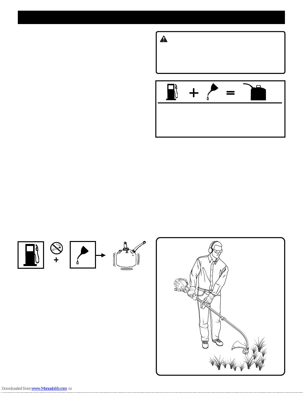
■Mix and store fuel in a container approved for gasoline.
■■
■■
■Mix fuel outdoors where there are no sparks or flames.
Wipe up any fuel spillage. Move 9 m (30 ft. ) away from
refuelingsitebeforestartingengine.
■■
■■
■Stoptheengineandallow to cool before refueling or
storing the unit.
■■
■■
■Allow the engine to cool; empty the fuel tank and secure
the unit from moving before transporting in a vehicle.
SPECIFIC SAFETY RULES FOR TRIMMER USE
■■
■■
■Replace string head if cracked, chipped, or damaged in
any way. Be sure the string head is properly installed
and securely fastened. Failure to do so can cause
seriousinjury.
■■
■■
■Make sure all guards, straps, deflectors and handles are
properlyandsecurelyattached.
■■
■■
■Useonlythemanufacturer'sreplacementstringinthe
cutting head. Do not use any other cutting attachment.
■■
■■
■Never operate unit without the grass deflector in place
andingoodcondition.
■■
■■
■Maintain a firm grip on both handles while trimming.
Keep string head below waist level. Never cut with the
string head located over 76 cm (30 in.) or more above
theground.
■■
■■
■The cutting attachment should stop turning when the
engine idles because it is equipped with a clutch. If the
cutting attachment continues to turn when the engine
idles, contact a service dealer for repair.

4
SYMBOLS
Important:Someofthefollowingsymbolsmaybeusedonyourtool.Pleasestudythemandlearntheirmeaning.Proper
interpretation of these symbols will allow you to operate the tool better and safer.
SYMBOL NAME EXPLANATION
Safety Alert Symbol Indicates danger, warning or caution. It means
attention!!! Your safety is involved.
ReadYourOperator’sManual Your manual contains special messages to bring
attention to potential safety concerns as well as
operatingandservicinginformation.Pleaseread all
the information carefully to assure satisfaction and
safe use.
Weareyeandhearingprotection. Weareyeandhearingprotectionwhenoperatingthis
equipment.
Keepbystandersaway. Keep all bystanders at least (15 m) 50 feet away.
Ricochet. DangerofRicochet.
Noblade. Do not install any type of blade on this unit.
RPMDecal Rotational direction and maximum speed of the shaft
for the cutting attachment.
Boots Wearnon-slip safety footwear when using this
equipment.
Gloves Wearnon-slip,heavy-dutygloves.
NoSmoking Do not smoke when mixing fuel or filling fuel tank.
Gasoline Useunleadedgasolineintendedforautomotiveuse
with an octane rating of 87 ([R + M] / 2) or higher.
Oil Use 2-cycle oil for air cooled engines.
Mix Gasoline andOil Mix the fuel mix thoroughly and also each time before
fueling.
Switch On/Off Switch
I = ON to Run
O = OFF to Stop
min-1
9,000

5
Thepurposeofsafety symbols is to attract your attention to possible dangers. The safety symbols, and the explanations
with them, deserve your careful attention and understanding. The safety warnings do not by themselves eliminate any
danger. The instructions or warnings they give are not substitutes for proper accident prevention measures.
SYMBOL MEANING
DANGER: Indicates an imminently hazardous situation which, if not avoided, will result in death or
seriousinjury.
WARNING: Indicates a potentially hazardous situation which, if not avoided, could result in death or
seriousinjury.
CAUTION: Indicates a potentially hazardous situation which, if not avoided, may result in minor or
moderate injury. It may also be used to alert against unsafe practices that may cause property damage.
NOTE: Advises you of information or instructions vital to the operation or maintenance of the equipment.
SAVE THESE INSTRUCTIONS
TECHNICAL DATA
Weight Without fuel andstring head ................................................................................................................4.07 Kg
Withoutfuel,w/string head ..................................................................................................................5.09 Kg
Fuel tank volume ................................................................................................................................................... 42.5cm3
Cuttingswath.......................................................................................................................................................... 432mm
Enginedisplacement ................................................................................................................................................ 30 cm3
Maximumengineperformance(in accordancewithISO8893) ............................................................................... 0.78kW
Maximum rotational frequency of the spindle ..................................................................................................... 9000min-1
EngineSpeed(rotationalfrequency)atrecommendedmax.spindlerotationalfrequency..................................12500min-1
Enginespeed(rotationalfrequency)atidle ...............................................................................................2800 -3200 min-1
Fuelconsumption(inaccordancewith ISO 8893) at max. engine performance................................................... 0.52 kg/h
Specific fuel consumption (in accordance with ISO 8893) at max. engine performance ...................................... 0.47 kg/h
Vibrationlevel idling - FrontHandle ................................................................................................................. 3.7 m/s2
RearHandle .................................................................................................................. 2.7 m/s2
Vibrationlevelracing FrontHandle ...............................................................................................................11.0 m/s2
RearHandle .................................................................................................................. 8.1 m/s2
Soundpressure level(inaccordance withEN ISO11806:1997,ISO 7917:1987) .........................................101 LpA(dBA)
Soundpowerlevel(inaccordancewithISO10884) ................................................................................... 108LwA(dBpA)
SYMBOLS

6
FEATURES
Fig. 1
STARTER GRIP
ENGINEHOUSING
THROTTLE TRIGGER
FRONT HANDLE
GRASS DEFLECTOR
CUTTING
LINE
IGNITION
SWITCH
THROTTLE
INTERLOCK
SHAFT
UNPACKING
INSTRUCTIONS
■■
■■
■Carefullyremovetheproductfromthecarton.
■■
■■
■Inspect the product to make sure no breakage or
damageoccurredduringshipping.
■■
■■
■Do not discard the packing material until you have
inspectedandoperatedtheproduct.
PACKING LIST FOR OWNER'S KIT
■■
■■
■Grassdeflector
■■
■■
■Fronthandle
■■
■■
■Mufflerguard, torxwrenchand screws
■■
■■
■Hardware
■■
■■
■Operator'smanual
KNOB
COUPLER

7
ATTACHING THE POWER HEAD TO THE
TRIMMER ATTACHMENT
See Figure 2.
ASSEMBLY
REMOVING THE ATTACHMENT FROM THE
POWER HEAD
Forremovingor changing the attachment:
1. Loosentheknob.
2. Push in the button and twist the shafts to remove and
separateends.
ATTACHING THE STORAGE HANGER
See Figure 3.
There are two ways to hang your attachment for storage.
■■
■■
■To use the hanger cap, push in the button and place the
hanger cap over end of the lower end attachment shaft.
Slightly rotate the cap from side to side until the button
locks into place.
■■
■■
■The secondary hole in the attachment shaft can be used
forhangingpurposesas well.
WARNING:
Be certain the knob is fully tightened before operating
equipment; check it periodically for tightness during use
to avoid serious injury.
The trimmer attachment connects to the power head by
means of a coupler device.
1. Loosen the knob on the coupler of the power head shaft
and remove the end cap from the attachment.
2. Push in the button located on the trimmer attachment
shaft. Align the button with the guide recess on the
powerheadcoupler and slide the two shafts together.
Rotate the trimmer attachment shaft until the button
locks into the positioning hole.
NOTE: If the button does not release completely in the
positioning hole, the shafts are not locked into place.
Slightlyrotatefromsidetosideuntilthebuttonislockedinto
place.
3. Tighten the knob securely.
WARNING:
Neverattachoradjustanyattachmentwhilepowerheadis
running. Failure to stop the engine can cause serious
personal injury.
Fig. 2
COUPLER
KNOB
TRIMMER ATTACHMENT
STRING TRIMMER
SHAFT
POSITIONING
HOLE
GUIDE
RECESS
Fig. 3
BUTTON
HOLE
HANGER CAP

8
ASSEMBLY INSTRUCTIONS:
GRASS DEFLECTOR
See Figure 4.
1. Remove wing nut, flat washer, lock washer, and bolt
from the Owner’s Kit.
2. Place grass deflector over shaft and bracket.
3. Install bolt through the slots in the tabs on grass
deflectorandbracket on driveshaft housing.
4. Install flat washer, lock washer and wing nut.
5. TightenSecurely.
ASSEMBLY
FRONT HANDLE
See Figure 5.
1. Place the handle base and the bracket on the driveshaft
housingbelowthe spacer.
2. Install the two handle base screws and nuts, but do not
tightencompletely.
3. Place the handle grip onto the handle base and install the
two screws.Tighten securely.
4. Adjust the position of the handle for best balance and
comfort.
5. Tighten the two handle base screws securely.
NOTE: Do not attempt to remove or modify the spacer.This
spacer limits the upper position of the handle grip.
See
Figure5.
Fig. 5
HANDLE
BASE
HANDLE BASE
SCREWS
SPACER
SCREWS
BRACKET
NUTS
HANDLE GRIP
GRASS
DEFLECTOR
BRACKET
BOLT
WINGNUT Fig. 4
FLAT
WASHER
LOCK WASHER

9
Fig. 6
BENT END OF
MUFFLER GUARD
OPENINGIN REAR
HOUSING
MUFFLER GUARD ASSEMBLY
See Figure 6.
1. Removemufflerguardand twoscrews fromtheowner's
kit.
2. Attach the muffler guard to the rear housing.
NOTE: Make sure the bent end of the muffler guard fits
securely into the opening of the rear housing.
3. Using the torx wrench supplied, install the two screws
andtighten securely.
ASSEMBLY
SCREWS MUFFLER
GUARD
REAR HOUSING
TORX
WRENCH

10
FILLING THE TANK
1. Cleansurface aroundfuel captoprevent contamination.
2. Loosen fuel cap slowly to release pressure and to keep
fuel from escaping around the cap.
3. Carefully pour fuel mixture into the tank. Avoid spillage.
4. Prior to replacing the fuel cap, clean and inspect the
gasket.
5. Immediately replace fuel cap and hand tighten. Wipe up
any fuel spillage. Move 9 m (30 ft.) away from refueling
sitebefore startingengine.
NOTE: It is normal for smoke to be emitted from a new
engine during and after first use.
WARNING
Always shut off engine before fueling. Never add fuel
to a machine with a running or hot engine. Move at
least 9 m (30 ft.) from refueling site before starting
engine. Do not smoke!
OPERATION
OPERATING THE TRIMMER
SeeFigure7.
Holdthetrimmerwith the right hand on the rear handle and
the left hand on the front handle.Keep a firm grip with both
handswhilein operation.Trimmershould beheldata
comfortable position with the rearhandleabout hip height.
Always operate trimmer at full throttle. Cut tall grass from
thetopdown.This will preventgrassfromwrappingaround
the driveshaft housing and string head which may cause
damagefrom overheating. Ifgrassbecomes wrapped
around the string head, stop the engine, disconnect the
sparkplugwire,andremovethegrass.Prolongedcuttingat
partial throttle will result in oil dripping from the muffler.
FUEL AND REFUELING
HANDLING THE FUEL SAFELY
■■
■■
■Always handle fuel with care, it is highly flammable.
■■
■■
■Alwaysrefuel outdoorswherethere areno sparksand
flames. Do not inhale fuel vapors.
■■
■■
■Do not let gasoline or oil come in contact with your skin.
■■
■■
■Keep gasoline and oil away from the eyes. If gasoline or
oil comes in contact with the eyes, wash them immedi-
ately with clean water. If irritation is still present, see a
doctorimmediately.
■■
■■
■Clean up spilled fuel immediately.
MIXING THE FUEL
■■
■■
■This product is powered by a 2-cycle engine and requires
pre-mixinggasolineand2-cycleoil.Pre-mixunleaded
gasoline and 2-cycle engine oil in a clean container
approvedforgasoline.
■■
■■
■Thisengineis certified to operate onunleadedgasoline
intended for automotive use with an octane rating of 87
([R + M] / 2) or higher.
■■
■■
■Do not use any type of pre-mixed gasoline/oil from fuel
service stations, this includes the pre-mixed gasoline/oil
intended for use in mopeds, motorcycles, etc.
■■
■■
■Use high a quality 2-cycle self mixing oil for air cooled
engines. Do not use automotive oil or 2-cycle outboard
oil.
■■
■■
■Mix 2% oil into the gasoline. This is a 50:1 ratio.
■■
■■
■Mix the fuel thoroughly and also each time before
fueling.
■■
■■
■Mix in small quantities. Do not mix quantities larger than
usable in a 30 day period. A 2-cycle oil containing a fuel
stabilizerisrecommended.
Fig. 7
1 Litre + 20 ml =
2 Litres + 40 ml =
3 Litres + 60 ml =
4 Litres + 80 ml =
5 Litres + 100 ml = }50:1

11
OPERATION
ADVANCING THE STRING
ADVANCING STRING USING THE EZ LINE™ TAP
ADVANCE SYSTEM
String advance is controlled by tapping string head on grass
whilerunningengine at full throttle.
1. Run engine at full throttle.
2. Tap string head on ground to advance string. String
advances each time the head is tapped.
3. Several taps may be required until string strikes the cut
off blade.
4. Resumetrimming.
NOTE: If the string is worn too short you may not be able to
advance the string by tapping it on the ground. If so, STOP
THEENGINE,andmanuallyadvance the string.
ADVANCING THE STRING MANUALLY
Pushthespoolretainerdownwhilepullingonstring(s)to
manuallyadvancethe string.
CUTTING TIPS
See Figure 8.
■Keep the trimmer tilted toward the area being cut; this is
the best cutting area.
■Do not cut in dangerous cutting area.
■Use the tip of string to do the cutting; do not force string
head into uncut grass.
■Wire and picket fences cause extra string wear, even
breakage. Stone and brick walls, curbs, and wood may
wearstringrapidly.
■Avoid trees and shrubs. Tree bark, wood moldings,
siding, and fence posts can easily be damaged by the
string.
GRASS DEFLECTOR LINE TRIMMING CUT-
OFF BLADE
See Figure 9.
This trimmer is equipped with a line trimming cut-off blade
on the grass deflector.For best cutting, advance string until
it is trimmed to length by the cut-off blade. Advance string
wheneveryou hear theenginerunning faster thannormal.
This will maintain best performance and keep string long
enoughto advanceproperly.
Fig. 9
BEST CUTTING
AREA
DANGEROUS
CUTTING AREA Fig. 8

12
1
OPERATION
IGNITION SWITCH
I = ON TO RUN
O = OFF TO STOP
Fig.10
THROTTLE
TRIGGER
THROTTLE INTERLOCK
PRIMER BULB
CHOKE
POSITION
HALF
CHOKE
POSITION
RUN POSITION
Fig.11
CHOKE LEVER
STARTING AND STOPPING
SeeFigures10 and 11.
TO START A COLD ENGINE:
1. Lay trimmer on a flat, bare surface. Move switch to “I”
(RUN)position.
NOTE: Unit is equipped with a positive on-off switch,
make sure switch is in the “I” (RUN) position before
starting the unit.
2. Push primer bulb 8 to 10 times.
3. Set choke lever to choke position ( ).
4. Depressinterlock,squeezetriggerandpullstarterrope
until engine tries to run. (No more than 6 pulls.)
5. Set choke lever to half choke position ( ).
6. Holdtriggerandpull starterropeuntil engineruns.
7. Run engine 30 to 45 seconds at full throttle (with trigger
depressed fully) on half choke position ( ) to warm
up. Move choke lever to run position ( ).
TO START A WARM ENGINE:
1. Move choke lever to run position ( ).
2. Holdtriggerandpull starterropeuntil engineruns.
TO STOP THE ENGINE:
To stop the engine, depress the switch to “O”position.
NOTE: Be sure to return the stop switch to the “I”(RUN)
position before trying to start unit.
WARNING:
Never start or run the engine inside a closed or poorly
ventilated area; breathing exhaust fumes can kill.

13
■Youmaymake adjustments and repairs described here.
For other repairs, have the trimmer serviced by an
authorizedservicedealer.
■Consequencesofimpropermaintenancemayinclude
excess carbon deposits resulting in loss of performance
and discharge of black oily residue dripping from the
muffler.
■Make sure all guards, straps, deflectors and handles are
properly and securely attached to avoid the risk of
personalinjury.
SPOOL REPLACEMENT
EZ LINE™ TAP ADVANCE SYSTEM
NEW PREWOUND SPOOL
SeeFigures12 and 13.
If replacing string only, refer to “String Replacement” later in
this manual.
Use only 2.0 mm (.080 in.) diameter monofilament string.
Usethemanufacturer's replacement string for bestperfor-
mance.
1. Stop the engine, disconnect the spark plug wire. Hold
thestring head andunscrewthe spoolretainer.Turn
counterclockwise.
2. Remove the empty spool from the string head. Keep the
spring attached to the spool.
3. To install the new spool, make sure the two strings are
captured in the slots opposite each other on the new
spool. Make sure the ends of each string is extended
approximately 152 mm (6 in.) beyond each slot.
4. Thread the strings into the eyelets in the string head.
Carefully push the spool into the string head (gently pull
the strings to the outside if necessary). When the spool
is positioned in the string head, grasp the strings and
pull sharply to release them from the slots in the spool.
5. Push down and turn the spool counterclockwise until it
no longer turns. Hold the spool down and rotate clock-
wise a small amount. Release the spool. The spool
should be locked down in the string head. If not, hold
downandrotateuntil locked.
MAINTENANCE
WARNING:
Useonlyoriginalmanufacturer's replacementparts,
accessories and attachments. Failure to do so can
cause possible injury, poor performance and may
voidyourwarranty.
EYELETS
SPRING
SLOTS
STRING HEAD
DRIVESHAFT
Fig.12
Fig.13
EYELETS
SPOOL
RETAINER
SPOOL
6. Make sure the string head and the spool retainer are
installed on the drive shaft by turning the retainer
clockwise to tighten.
7. Pull the strings again to rotate the spool into cutting
position.Pushthe spool retainer down whilepullingon
string(s) to manually advance the string and to check for
proper assembly of the string head.

14
STRING REPLACEMENT
See Figures 14, 15, 16 and 17.
1. Stop the engine, disconnect the spark plug wire. Hold
thestring head andunscrewthe spoolretainer.Turn
counterclockwise.
2. Remove the spool from the string head. NOTE: Keep
the spring attached to the spool. Remove any old string
remainingonthespool.
3. Cut two pieces of string, each being approximately
2.7 m (9 ft.) long.
4. Insert the first string into the anchor hole in the upper
part of the spool. Wind the first string around the upper
part of the spool counterclockwise, as shown by the
arrows on the spool. Place string in the slot on upper
spool flange, leaving about 152 mm (6 in.) extended
beyond the slot. Do not overfill. After winding the string,
there should be at least 6 mm (1/4 in.) between the
wound string and the outside edge of the spool.
5. Repeat above step with second string, using the bottom
part of spool. Do not overfill.
6. Replace the spool and the spool retainer. Refer to "Spool
Replacement " earlier in this manual.
CLEANING THE EXHAUST PORT AND
MUFFLER
Depending on the type of fuel used, the type and amount of
oil used, and/or your operating conditions, the exhaust port
and muffler may become blocked with carbon deposits. If
you notice a power loss with your gas powered tool, a
qualified service technician will need to remove these
depositsto restore performance.
SPARK ARRESTOR
The spark arrestor must be cleaned or replaced every 25
hoursoryearly to ensure proper performanceofyour
product. Spark arrestors may be in different locations
dependingon the model purchased.Pleasecontactyour
nearest service dealer for the location of the spark arrestor
foryour model.
CleaningInstructions:
■■
■■
■Remove the spark arrestor from the muffler.
■■
■■
■If your spark arrestor is made of a fiberglass material,
discardandreplace.
■■
■■
■If your spark arrestor is made of a metal material follow
these cleaning instructions:
1. Spray the spark arrestor with a quality carbon
cleaner.
2. Gently clean using a wire brush.
3. Installthe new or cleaned spark arrestor and reas-
semblecompletelybefore use.
MAINTENANCE
FIRST STRING Fig.14
SPOOL
ANCHOR
HOLE
SECOND
STRING
ARROWSON
SPOOL
Fig.16
Fig.17
SLOT ARROWSON
SPOOL
SPRING
Fig.15
FIRST STRING
SLOT

15
The fuel cap contains a non-serviceable filter and a check
valve. A clogged fuel filter will cause poor engine perfor-
mance. If performance improves when the fuel cap is
loosened, check valve may be faulty or filter clogged.
Replacefuelcap if required.
SPARK PLUG
This engine uses a Champion RCJ-6Y with 0,63 mm
(.025 in.)electrodegap.Usean exact replacement and
replaceannually.
TRANSPORTING
Allowtheengineto cool; empty the fuel tank and secure the
unitfrommovingbeforetransporting.
STORAGE
STORAGE (LESS THAN 1 MONTH)
1. Clean all foreign material from the trimmer. Store it in a
well-ventilated place that is inaccessible to children.
Keep away from corrosive agents such as garden
chemicals and de-icing salts.
2. Abide by all ISO and local regulations for the safe
storage and handling of gasoline. Excess fuel should be
usedupinother2-cycleenginepoweredequipment.
STORAGE (1 MONTH OR LONGER)
1. Drain all fuel from tank into a container approved for
gasoline. Run engine until it stops.
2. Clean all foreign material from the trimmer. Store it in a
well-ventilated place that is inaccessible to children.
Keep away from corrosive agents such as garden
chemicals and de-icing salts.
3. Abide by all ISO and local regulations for the safe
storage and handling of gasoline. Excess fuel should be
usedupinother2-cycleenginepoweredequipment.
REPLACING AND CLEANING AIR FILTER
SeeFigures18 and 19.
Forproperperformance and long life, keep air filter clean.
1. Remove the air filter cover by pushing down on the latch
with your thumb while gently pulling on the cover.
2. Remove the filter, clean it in warm soapy water. Rinse
and let dry completely. For best performance, replace
annually.
3. Install the filter, align tabs, push in, and make sure the
latches are locked into place.
WARNING:
A leaking fuel cap is a fire hazard and must be
replacedimmediately.
MAINTENANCE
FUEL CAP
AIR FILTER
COVER
FILTER
Fig.18
Fig. 19
LATCH
PULL COVER
TOOPEN

16
TROUBLESHOOTING
PROBLEM POSSIBLE CAUSE SOLUTION
IFTHESE SOLUTIONS DO NOT SOLVETHE PROBLEM CONTACTYOUR AUTHORIZED SERVICE DEALER.
1. Check spark. Remove spark plug. Reattach
the spark plug cap and lay spark plug on metal
cylinder. Pull the starter rope and watch for
spark at spark plug tip. If there is no spark,
repeat test with a new spark plug.
2. Push primer bulb until bulb is full of fuel. If
bulb does not fill, primary fuel delivery system
is blocked. Contact a service dealer. If primer
bulb fills, engine may be flooded (see next
item).
3. Remove spark plug, turn trimmer so spark plug
hole is aimed at the ground. Move choke lever
to “RUN” and pull starter cord 10 to 15 times.
This will clear excess fuel from engine. Clean
and reinstall spark plug. Pull starter three
times with choke lever at “RUN”. If engine
does not start, move choke lever to “CHOKE”
andrepeatnormalstartingprocedure.Ifengine
still fails to start, repeat procedure with a new
sparkplug.
4. Contact a service dealer.
Turn “L”needlecounterclockwise 1/16 turn. If
“L”low needle cannotbe turned counterclock-
wise, do not force plastic limiter caps. Contact a
servicedealer.
SeeFigure20.
Turn“H”needlecounterclockwise1/16turn.If
“H”highneedlecan notbe turnedcounterclock-
wise, do not force plastic limiter caps. Contact a
servicedealer.
SeeFigure20.
1. Use fresh fuel and the correct 2-cycle oil mix.
2. Cleanthe air filter. Refer to“Replacingand
Cleaning the Air Filter ” earlier in this manual.
3. Turn “H” needle clockwise 1/16 - 1/8 turn.
See
Figure20.
Turn idle speed screw clockwise to increase idle
speed.
1. Lubricate with silicone spray.
2. Install more string. Refer to “String Replace-
ment”earlier in this manual.
3. Pull strings while alternately pressing down on
andreleasingspoolretainer.
4. Removestring from spool andrewind.Refer to
“StringReplacement”earlierinthismanual.
5. Advance string at full throttle.
Engine will not start:
Engine starts but will not
accelerate:
Engine starts but will only
run at high speed at half
choke:
Engine does not reach full
speed and emits excessive
smoke:
Engine starts, runs, and
accelerates but will not idle:
String will not advance:
1. Nospark.
2. Nofuel.
3. Floodedengine.
4. Starterropepullshardernowthan
whennew.
Carburetorrequiresadjustment.
1. Check oil fuel mixture.
2. Air filter dirty.
3. Carburetorrequiresadjustment.
Carburetorrequiresadjustment.
1. String welded to itself.
2. Notenough stringonspool.
3. Stringworn too short.
4. Stringtangled onspool.
5. Enginespeed too slow.

17
1
TROUBLESHOOTING
PROBLEM POSSIBLE CAUSE SOLUTION
IFTHESE SOLUTIONS DO NOT SOLVETHE PROBLEM CONTACTYOUR AUTHORIZED SERVICE DEALER.
1. Cut tall grass from the top down.
2. Operate trimmer at full throttle.
Clean threads and lubricate with grease - if no
improvement,replacespoolretainer.
1. Operate trimmer at full throttle.
2. Use fresh fuel and the correct 2-cycle oil mix.
3. Cleanairfilter.Refer to“Replacing and
Cleaning the Air Filter” earlier in this manual.
4. Turn “H” needle clockwise 1/16 - 1/8 turn.
See
Figure20.
Grasswrapsaround
driveshafthousingand
stringhead:
Spoolretainerhardtoturn:
Oil drips from muffler:
1. Cutting tall grass at ground level.
2. Operatingtrimmerat partthrottle.
Screwthreadsdirtyordamaged.
1. Operatingtrimmeratpart throttle
2. Check oil/fuel mixture.
3. Air filter dirty.
4. Carburetorrequiresadjustment.
Fig.20
NOTE:Thecarburetoradjustmentneedle(s) are equippedwithplastic
cap(s)thatprevents counterclockwise rotation from the original
factory adjustment. If your unit exhibits specific performance
problem(s)where theTrouble ShootingSectionrecommends a
counterclockwiseneedleadjustment and no adjustmentshavebeen
made since original purchase, the unit should be taken to a factory
authorized service dealer for repair.In most cases, the needed
adjustment is a simple task for the factory trained service representa-
tive.
“L”LO
NEEDLE
“H”HIGH
NEEDLE
IDLE SPEED
SCREW
SOUND POWER/PRESSURE & HANDLE VIBRATION CHART FOR STRING TRIMMERS /
BRUSHCUTTERS
Information on Noise Emission per European Machine Safety Directive 98/37/EC.
Theindividualequipmentlisted was operated in a manner consistent with normal working conditions.
The A-weighted sound pressure level (LpA) at the operator’s ear and the A-weighted sound power level (LWA) were both
measuredin accordance withDirective79/113/EEC. Hearing protectionisrecommended where levelsexceed85 dBA.
Handle vibration was measured in accordance to ISO 7916. Read the safety precautions section of the manual.
SOUNDPRESSURE SOUNDPOWER VIBRATION
MODEL LpA(dBA) LwA(dBpA) m/s2
PLT3043S 101 108 11.0
SAFETY DIRECTIVE

18
WARRANTY
GUARANTEE
GUARANTEE – STATEMENT
(RTSA / RTUK / RTG)
AllRyobiproducts are guaranteed from defects in material and workmanship,foraperiod of twenty-four (24)
months, effective and evidenced from date of original invoice or delivery note.
Defects caused bynormalwearandtear,unauthorized/improper maintenance/handling oroverloadareexcluded
from this guarantee as are accessories such as battery packs, bulbs, blades and bits,etc.
In the event of malfunction within the guarantee period, please return the assembled product with proof of purchase,
toyourdealer or nearest Ryobi Service Centre.
Your statutory rights in respect of defective products remain unaffected by the warranty.
RyobiTechnologies GmbH,Itterpark7,D-40724 Hilden, Germany
RyobiTechnologies, Customer Services, Anvil House,Tuns Lane, Henley-on-Thames, RG9 1SA, UK
RyobiTechnologies, BP 50012 - 95945 Roissy CDG Cedex – FRANCE
RyobiTechnologies Australia PTY Limited,359-361 HorsleyRoad, Milperra, NSW2214Australia

19
NOTES

RY70113
983000-225
3-03
RyobiTechnologies GmbH
Itterpark 7
D-40724 Hilden
Germany
Tel.: +49 (0)2103 / 29 58 0
Fax : +49 (0)2103 / 29 58 29
RyobiTechnologies
Customer Services
Anvil House
Tuns Lane
Henley-on-Thames
RG9 1SA
UK
RyobiTechnologies
BP 50012 - 95945 Roissy CDG Cedex – FRANCE
RyobiTechnologies Australia PTY Limited
359-361 Horsley Road, Milperra, NSW 2214 Australia
OPERATOR'S MANUAL
StringTrimmer
PLT3043S
Other manuals for PLT3043S
1
Table of contents
Other Ryobi Trimmer manuals

Ryobi
Ryobi RY253SS User manual

Ryobi
Ryobi P20014 User manual

Ryobi
Ryobi RHT36 User manual

Ryobi
Ryobi RY29550 User manual

Ryobi
Ryobi RFT254 User manual

Ryobi
Ryobi ONE+ RY18LMC30A User manual

Ryobi
Ryobi RY52001, RY52001A User manual

Ryobi
Ryobi R18XPHTA0 User manual

Ryobi
Ryobi RBCGM25BB User manual

Ryobi
Ryobi RY36LT33A User manual

Ryobi
Ryobi RLT1825M13 User manual

Ryobi
Ryobi P26010 User manual

Ryobi
Ryobi RBC30SET User manual

Ryobi
Ryobi OLT1830 User manual

Ryobi
Ryobi AC04156 User manual

Ryobi
Ryobi AC14RFL User manual

Ryobi
Ryobi RY25CSEMC User manual

Ryobi
Ryobi RLT1830H15 User manual

Ryobi
Ryobi RY41130 User manual

Ryobi
Ryobi 780r User manual