saalasti Crush HF Series User manual

This document is PROPERTY of
SNEF BRASIL
Rua Desembargador Edésio Fernandes, 122
30494-450 –Belo Horizonte, MG –BRASIL
Note protection DIN 34.
Notes:
1 - This document complies with contract requirements.
Este documento é PROPRIEDADE de
SNEF BRASIL
Rua Desembargador Edésio Fernandes, 122
30494-450 –Belo Horizonte, MG –BRASIL
Observar proteção DIN 34.
00
25/07/19
J
SAALASTI
ADRIANO M.
ADRIANO M.
APPROVED
REV.
DATE
TYPE
EXECUTED
CHECKED
APPROVED
REVISION DESCRIPTION
REVISIONS
ISSUE TYPE
(A) PRELIMINARY
(B) FOR APPROVAL
(C) FOR KNOWLEDGE
(D) FOR BIDDING
(E) FOR CONSTRUCTION
(F) AS PURCHASED
(G) AS BUILT
(H) CANCELLLED
(J) APPROVED
ABIODIS –BIOMASS UNIT
AREA:
THERMAL POWER PLANT
SPECIALITY:
MECHANICAL ENGINEERING
SET:
BIOMASS FEEDING SYSTEM
RESPONSIBLE PERSON
DATA
SUB SET:
WOOD CHIPPER
ELABORATED:
SAALASTI
11/07/19
TITLE:25
CHIPPER MAINTENANCE AND USER MANUAL
EXECUTED:
SAALASTI
11/07/19
SNEF NUMBER:
1216-H180-06-MIS-02276
SHEET:
1
FORMAT:
A4
CHECKED:
ADRIANO M.
25/07/19
CLIENT NUMBER:
FOLLOW:
25
REVISON:
00
APPROVED:
ADRIANO M.
25//07/19
1216-H180-06-MIS-02276-00

1216-H180-06-MIS-02276-00
SUMMARY
1. ENGLISH VERSION……………………………………………………………….…03
2. VERSION FRANÇAISE……………………………………………………………...50

Saalasti Crush HF Series 2 (47)
VM-20190708 Operation and maintenance manual 08.07.2019
Table of Contents
1INTRODUCTION.......................................................................................................................3
2OPERATION PRINCIPLE.........................................................................................................4
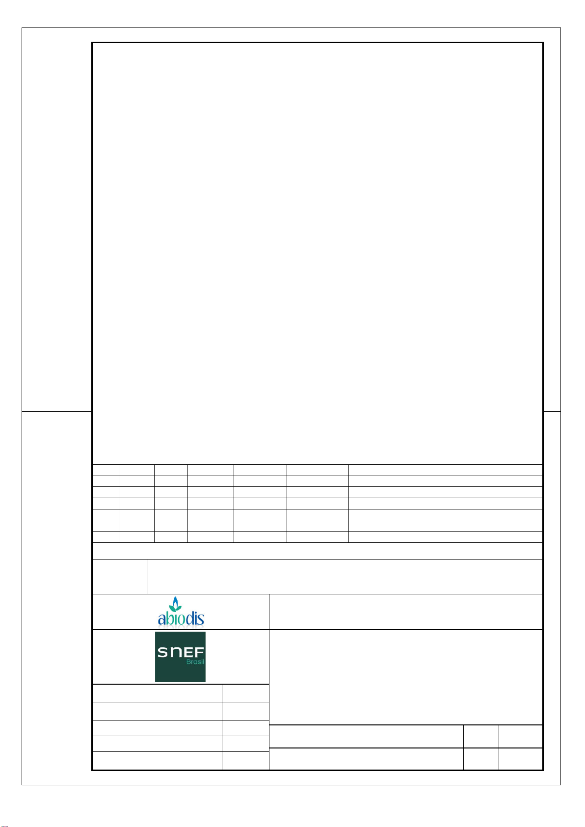
2.1 Frame........................................................................................................................................4
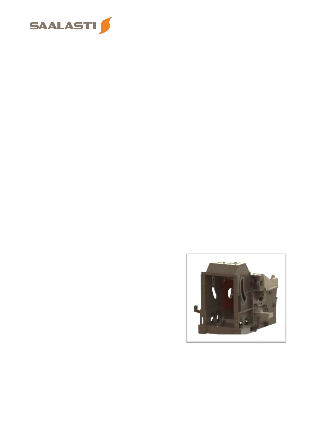
2.2 Lower rolls...............................................................................................................................5
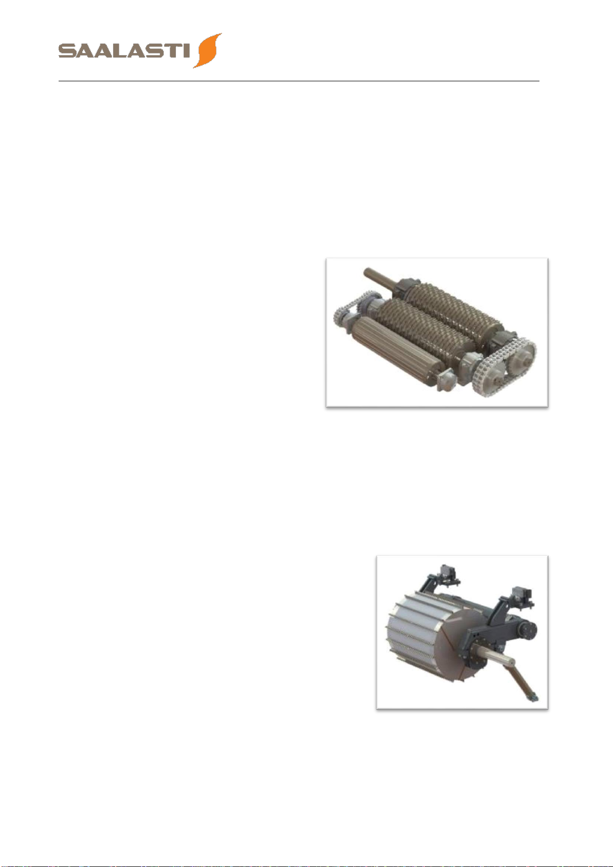
2.3 Upper roll .................................................................................................................................5
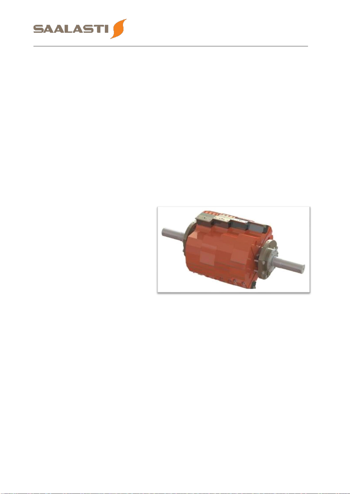
2.4 Rotor.........................................................................................................................................6
2.5 Anvil Plate................................................................................................................................7
2.6 Grate.........................................................................................................................................7
3OPERATING INSTRUCTION...................................................................................................9
3.1 Before starting the Saalasti Crush........................................................................................9
3.2 Starting the Saalasti Crush ....................................................................................................9
3.3 Stopping the Saalasti Crush..................................................................................................9
3.4 Fuel selection ..........................................................................................................................9
3.5 Disturbance situations ...........................................................................................................9
4SAFETY INSTRUCTIONS......................................................................................................10
4.1 Safety in operation................................................................................................................10
4.2 Safety in maintenance ..........................................................................................................11
5MAINTENANCE......................................................................................................................15
5.1 Rotor cutting tools change ..................................................................................................15
5.2 Anvil plate cutter inserts ......................................................................................................19
5.3 Anvil plate wear plate ...........................................................................................................20
5.4 Anvil plate pins......................................................................................................................21
5.5 Grate pins...............................................................................................................................22
5.6 Changing a shear pin............................................................................................................23
5.7 Grate.......................................................................................................................................25
5.8 Frame wear plates.................................................................................................................27
5.9 V-belts ....................................................................................................................................27
5.10 Gear boxes.............................................................................................................................31
5.11 Lubrication.............................................................................................................................32
6HYDRAULICS.........................................................................................................................35
6.1 Hydraulic pump.....................................................................................................................36
6.2 Air/Oil cooler..........................................................................................................................36
6.3 Immersion heater ..................................................................................................................36
6.4 Tank equipments...................................................................................................................37
6.5 Oil purity.................................................................................................................................37
6.6 Electrovalves in hydraulic unit............................................................................................38
6.7 Starting hydraulic unit in automatic mode.........................................................................38
6.8 Upper roll height adjustement .............................................................................................39
6.9 Manual valves in hydraulic unit...........................................................................................40
6.10 Using hydraulics in maintenance........................................................................................41
6.11 Regular maintenance............................................................................................................47
6.12 Safety......................................................................................................................................47

Saalasti Crush HF Series 3 (47)
VM-20190708 Operation and maintenance manual 08.07.2019
1 Introduction
This document contains operation and maintenance manual of Saalasti Crush
Horizontal Feeding Series.
Saalasti Crush HF Series is CE marked and fulfills mechanical equipment directive
2006/42/EC.
The Saalasti Crush has been designed according to ATEX-directives 99/92/EC and
94/9/EC. Separate ATEX-classification document is available upon request from the
manufacturer.
The Saalasti Crush reliable operation, safety and long useful lifetime essentially
depend on three factors:
•Careful installation
•Quality and regularity of the checks, maintenance and repairs
•Compliance with the given operation instructions
Saalasti Crush has been designed to predefined operation condition. Feed material
and velocity together with environment conditions has affected to shredders
mechanical design and into mechanism performance. In consequence of this
matter, the use of shredder in any other than planned is prohibited.
If you do not find the answer to a question or a problem in this document, please
contact the manufacturer.
Due to our continuing program of research and development, the specifications
herein are subject to change without notice
The machine should be operated by skilled operators according to
the instructions of Saalasti and according to the machine's
operation and maintenance manuals.

Saalasti Crush HF Series 4 (47)
VM-20190708 Operation and maintenance manual 08.07.2019
2 Operation principle
Saalasti Crush HF is a horizontal axis crusher which has a high speed rotating rotor.
The Saalasti Biomass Feeder feeds the untreated fuel to the crusher infeed case. In
the infeed case is located the feeding rolls: the upper and the lower rolls, which feed
untreated fuel to rotor. The upper roll moves vertically with hydraulic cylinders. The
force against the fuel is adjusted automatically by DCS. The upper and the lower roll
speed can vary depending of the fuel being processed. Rotor crushes the fuel
against anvil plate and the grate where fuel achieves the final particle size.
The rotor cutting tools crush the fuel with high velocity and grind in the gap between
the anvil plate and the cutting tools and finally between the grate and the cutting
tools.
The Saalasti Crush is designed to handle small rocks and metal pieces. These will
be crushed smaller and fall down with the processed fuel. In case of bigger stones
and thick metal pieces the Saalasti Crush is equipped with a safety system which
releases anvil plate in exceptional situation. The grate is also equipped with the
same shear pin protection. When anvil plate and grate are released the object can
fall down before rotor without ruining the Saalasti Crush. Returning the anvil plate
and the grate should be done with hydraulics when the Saalasti Crush is stopped.
Protective parts replacement can be done when anvil plate and/or grate are
returned to operation place.
For Saalasti Crush hydraulic functions there is a hydraulic unit. Hydraulics are used
by cylinders for the anvil plate return system, the grate return, the upper rotor
position adjustment and the upper case opening.
2.1 Frame
The frame of the Saalasti Crush is welded to
the embedded steel over the discharge
opening. The frame consists of an infeed case,
a lower case and an upper case which are
bolted together.
The infeed case and rotor casing is equipped
with replaceable wear plates. See drawings for
details.
There is a service hatch on the top of infeed
case for maintenance lifts. Another service
hatch is located on the back wall of the lower
case in order to access below the Saalasti
Crush. Note: All hatches must be closed during operation!
The upper case is bolted to the infeed case and to the lower case with screws. The
upper case can be opened in maintenance simply by unscrewing the bolts and
opening the upper case with hydraulics. Note: When upper case is open, always
remember to lock it open with the safety pins!

Saalasti Crush HF Series 5 (47)
VM-20190708 Operation and maintenance manual 08.07.2019
The aluminum work platform should always be installed in the opening behind the
grate unless opening is used for lifting parts from inside the Saalasti Crush.
There is a safety switch indicating when the upper case is close. Operation of the
rotor motors are prevented if the upper case is not closed.
2.2 Lower rolls
The lower rolls and the upper roll receive untreated biofuel from the Saalasti
Biomass Feeder. The rolls feed untreated biofuel with predefined speed to the rotor.
There are three lower rolls, the rolls are
called front roll, middle roll and drive
roll in the feeding direction. The drive is
naturally at drive roll. The drive roll
rotates the middle roll with a chain
drive and the middle roll rotates also
the front roll with chain drive.
The drive roll is driven by an electric
motor and a gear box. The gear box is
connected directly to the motors shaft
by Spidex coupling. The electric motor
rotates at variable speed; in two
directions.
The front roll is equipped with a rotation guard. If the rotation guard detects no
rotation, the feeding rolls (upper & lower rolls) and the Saalasti Biomass Feeder
stop.
The lower rolls shafts come through the infeed case. The bearings are mounted to
the bearing houses at both sides of the infeed case.
2.3 Upper roll
The upper and lower rolls receive untreated
biofuel from the Saalasti Biomass Feeder. The
rolls feed untreated biofuel with predefined
speed to the rotor.
The upper roll is driven by an electric motor and
a gear box. The gear box is connected to the
motors shaft by belt drive. The electric motor
rotates at variable speed; in two directions.
The upper roll is equipped with a rotation guard.
The rotation guard stop the feeding if no rotation
is detected.
The upper rolls shafts come through the infeed case. The bearings are mounted to
the pressure arms on both sides of the infeed case.

Saalasti Crush HF Series 6 (47)
VM-20190708 Operation and maintenance manual 08.07.2019
The Biomass Feeder and feeding rolls speeds (motor frequencies) are
synchronized. All three motors are driven with common start/stop signal and
common speed value.
The upper roll moves vertically with hydraulic cylinders. Each fuel has preset height
value, and hydraulics tries to maintain that value. The fuel can also push upper roll
higher.
The gear box and the motor are installed to the shaft, and moves together with the
upper roll. The upper roll shaft trough hole in the infeed case is sealed with end
plates. End plates and shaft sealing move with the upper rotor press arm against
end gliding plate bolted to the infeed case.
Upper roll up-position is limited mechanically by limiter rubber bolted to the frame.
2.4 Rotor
The actual crushing consists of a rotor, an anvil plate and a grate below the rotor.
The rotor is driven by 1 or 2
main drive motor(s) and V-
belt drive(s). Electric motor(s)
rotates at constant speed,
always forward.
The rotor is equipped with a
rotation guard. The rotation
guard stops equipment
according to interlocking.
The rotor is equipped with a
0-speed guard. The rotor
does not start unless rotor is completely stopped. The upper case opening
hydraulics is disabled if the rotor does not standstill.
The rotor safety relay is installed in the cross connection box on the Saalasti Crush
frame. The inductive sensor connected to the relay indicates the rotation speed of
the rotor.
The rotor shaft comes through the crusher frame. The bearings are mounted to the
bearing houses at both sides of the crusher.
The rotor is equipped with cutting tools. The cutting tools are bolted and easily
replaceable. The tightening moment of the cutting tools are high and exact. There is
a possibility to use several cutting tool types.

Saalasti Crush HF Series 7 (47)
VM-20190708 Operation and maintenance manual 08.07.2019
2.5 Anvil Plate
The rotor crushes the material mainly against the anvil plate and the anvil cutter
inserts. The anvil plate wear plate and anvil plate cutter inserts are bolted and easily
replaceable.
The Anvil plate is hinged to the
Saalasti Crush frame. At the rotor side
the anvil plate is supported by shear
pins.
If the fuel contains a large metal piece
or a big stone, the anvil plate opens by
breaking the protection pins. This
reduces damages to the crusher. The
alien object drops through the
discharge chute and continues in
process if not removed from the discharge conveyor.
The anvil plate position is monitored by inductive switch. The switch is located in
hinge pin at left side of the Saalasti Crush. The anvil plate opening interlocks the
feeding and discharge conveyor.
Anvil plate can be returned back with two levers, located on both side of the
crusher. The levers are driven by hydraulic cylinders. The cylinders are driven by
directional hand valve. Both anvil plate returning cylinders have a close limit switch;
which interlocks the feeding. If the cylinders are not closed properly in operation, the
returning mechanism breaks if the anvil plate opens against the levers.
If either side cylinder opens, the feeding is stopped.
2.6 Grate
The rotor crushes the material also against
the edges of the grate. The small particles
drop through the grate to the discharge
chute.
The grate is welded from plates, where
every cutting edge is hard face welded.
The grate can be repaired by welding worn
parts of the grate. For re-welding the grate
must be removed from the Saalasti Crush.
The grate front end is supported from the
crusher frame side plates with shear pins.
The rear end of the grate is supported with
hinge pins.
If the fuel contains a large metal piece or a big stone, also grate can open to reduce
damages to the crusher. When the grate opens, the shear pins break, and those
must be replaced by new ones in maintenance.

Saalasti Crush HF Series 8 (47)
VM-20190708 Operation and maintenance manual 08.07.2019
The grate position is monitored by inductive sensor at the left hinge pin. The grate
opening interlocks the feeding and discharge conveyor.
The grate can be returned back with hydraulic cylinders, located on both side of the
crusher. The cylinders are driven by directional hand valve. After the grate is
returned back, the shear pins must be replaced by new ones.
Both returning cylinders have a close limit switch; which interlocks the feeding. If
cylinders are not closed in operation, the returning mechanism breaks if the grate
opens against the levers.

Saalasti Crush HF Series 9 (47)
VM-20190708 Operation and maintenance manual 08.07.2019
3 Operating instruction
The Saalasti Crush is remote controlled. When in operation, the grab driver selects
the fuel type and loads the fuel to the Saalasti Biomass Feeder. In disturbance
situations; for example when metal is detected in fuel, the grab driver’s
responsibility is to remove the metal from the Saalasti Biomass Feeder.
3.1 Before starting the Saalasti Crush
Before starting the Saalasti Crush, always make sure that nothing is
preventing the rotor from rotating freely! If the Saalasti Crush has
previously stopped while crushing and some material is still blocked
between the feeding rolls and the rotor, the crusher must be cleaned!
3.2 Starting the Saalasti Crush
The system can be started in automatic mode, by pressing the START button in the
system remote control.
3.3 Stopping the Saalasti Crush
The Saalasti Biomass Feeder and discharge conveyors should be driven empty
before stopping the Saalasti Crush.
Due to main rotor high moment of inertia, the main rotor keeps
rotating about 15 minutes after power has been shut off without
braking option.
The system can be stopped in automatic mode, by pressing the STOP button in the
system remote control.
3.4 Fuel selection
According to the type of biomass to feed, the grab driver must select in the program
the correct fuel selection (affects feeding speed and upper roll vertical position):
•Selection 1 = Round wood Ø < 400mm
•Selection 2 = Round wood Ø > 400mm
•Selection 3 = Bundles
•Selection 4 = Pre-cut stumps
•Selection 5 = Full stumps
•Selection 6 = Other material
It is possible to stop or reverse the feeding (Biomass Feeder, upper and lower rolls)
with remote control during operation.
3.5 Disturbance situations
If an interlocking from one of the following conveyor system occurs, the rotor is left
running and the feeding stops according to interlocking. The rotor must be stopped
individually if disturbance time last for a long time.

Saalasti Crush HF Series 10 (47)
VM-20190708 Operation and maintenance manual 08.07.2019
4 Safety instructions
National safety legislation and factory safety regulations must fulfill
when working nearby the Saalasti Crush.
4.1 Safety in operation
Noise inside the shelter building is above 85 dB (A). Hearing protector must
be used. Unnecessary stay in the shelter building must be avoided.
All service hatches must be closed during the use. Opening the
Saalasti Biomass Feeder service hatch during operation is particularly
dangerous.
Do not use the machine for any other than its designed purposes.
Never use the machine if any of its safety devices or guards are missing, or are not
in correct working condition.
The area around the machine and its operation and control devices should be kept
free of any obstacles and debris.
The area around the crusher must be cleaned regularly to prevent dust
explosion due to accumulation of small biomass particle inside the shelter
building.
Be aware of all electrical connections. Particularly main drive is using high
voltage and/or high current.
Some parts of the Saalasti Crush, like the main rotor bearings can be hot.
Smoking near the crusher is forbidden. Risk of fire!

Saalasti Crush HF Series 11 (47)
VM-20190708 Operation and maintenance manual 08.07.2019
4.2 Safety in maintenance
General safety instruction during maintenance:
Follow the maintenance and repair instruction given by manufacturer.
Because of danger of fire the machine have to be washed in and outside before
maintenance (particularly if welding must be done). Smoking is forbidden.
Only properly trained person is allowed to maintain and repair the
Saalasti Crush.
Before begin the maintenance work ensure that:
All safety switches must be opened and locked with personal padlock.
Rotor must be fully stopped. Let the rotating rotor stop by itself. Do not try to
decelerate or stop the rotor. Run down time of the main rotor is about 15 min. It’s
forbidden to open upper case fastening bolts before rotor is completely stopped.
Discharge conveyor must be stopped and locked with a personal padlock.
Discharge chute must also clean up from wood chippings grind which could fall over
the technician.
If the upper case needs to be open to carry out maintenance work, make sure you
secure the upper case once opened with the safety pins (cf. hydraulics instruction
manual to check how to open the upper case safely).
Remove the 2 pins from the back wall of
crusher (on both side of the service hatch).
And install the pins to secure the upper
case.

Saalasti Crush HF Series 12 (47)
VM-20190708 Operation and maintenance manual 08.07.2019
After the safety pins are
locked, the maintenance
work can be done safely.
If some maintenance works as to be done inside the Saalasti Crush, on the feeding
rolls or anvil plate, the upper roll must be driven up to the highest position and
secure with 2 safety pins.
When performing maintenance work:
When using the hydraulics, ensure that nobody get squeezed in- or
outside of the crusher. It’s forbidden to use service hydraulics and
hydraulic pump must be stopped and secured if somebody is inside
the machinery.
Use safety glasses when carrying out maintenance work.
Use breathing protection mask when carrying out maintenance work.
✓
✓

Saalasti Crush HF Series 13 (47)
VM-20190708 Operation and maintenance manual 08.07.2019
The hydraulic pressure line manual direction valve is required to keep closed when
hydraulics is not needed.
When upper case is open, the aluminum work platform must be installed in the
opening behind the rotor, unless opening is needed for lifting parts through.
When working below the crusher, a work platform (not included in delivery) must be
installed inside the chute.
Main rotor must always be locked mechanically with wooden wedge, when working
on it.
When rotating the rotor manually, always turn it in the reverse direction.
Before starting the crusher after maintenance:
Before starting the Saalasti Crush, always make sure that nothing is
preventing the rotor from rotating freely!
X
✓

Saalasti Crush HF Series 14 (47)
VM-20190708 Operation and maintenance manual 08.07.2019
Make sure that the anvil
plate and grate lifting levers
are in correct position
before starting the Saalasti
Crush. More details on how
to operate the hydraulic
cylinders are given in
chapter 6 Hydraulics.
Always remove the anvil plate
drawbar before starting the
Saalasti Crush. Note that the
crusher is delivered in this
configuration, so do not forget
to remove them before the
first start.
X
✓
✓
Anvil plate cylinders
and lifting arms
Grate cylinders and
lifting arms
X

Saalasti Crush HF Series 15 (47)
VM-20190708 Operation and maintenance manual 08.07.2019
5 Maintenance
The maintenance instructions given by the manufacturer should be followed to
ensure reliable operation and long operating life of the Saalasti Crush. The
components of the crusher are heavy with high inertia. Any maintenance operations
carried out otherwise than instructed may cause personal injuries. In addition to the
specific maintenance and repair measures, the following general instructions have
to be complied with whenever the Saalasti Crush is maintained or repaired.
Carefully study the safety instructions before starting any maintenance work.
The parts changing or repair interval depends on untreated material quality and
material flow.
This manual contains the most common maintenance works. If instructions can’t be
found in documentation, contact the manufacturer for receiving an exact guide or
other assistance.
5.1 Rotor cutting tools change
The wear of the cutting tools reduces the capacity of the Saalasti Crush, increases
the biomass particle size and the main drive power consumption. Although the
capacity reduction is relatively small, the cutter bars have to be changed sufficiently
often to maintain a good capacity and efficiency together with shredding ability.
Block the rotor (e.g. with wooden wedge) to prevent it from rotating
while cutting tool change is in progress!
The Saalasti Crush HF series are usually delivered with chipper knives or cutter
bars, depending on the main material processed. However, it is possible to switch
from one cutting tool to the other easily, by changing the holders.
Always change all cutting tools to keep the rotor balanced.
Do not use damage bolts!
Always install new chipper knives that have been equally wear (same
length of available material left) to make sure they all weight
approximately the same and therefore keep the rotor well balance.

Saalasti Crush HF Series 16 (47)
VM-20190708 Operation and maintenance manual 08.07.2019
Chipper knife change:
After opening the Saalasti Crush upper case and installing
the service platform proceed to the following steps (for more
detailed drawings, please refer to the attached drawings):
Loosen the chipper knives bolts (4 bolts per chipper
knife). To ease and speed up the chipper knife
change, Saalasti recommend using an air gun.
Remove the chipper knife by lifting a bit the
clamp (use one of the bolt to lift it like it is
shown on the picture).
After removing the chipper knife, always clean with
compress air the gap between the chipper knife
clamp and holder. All the dust must be removed to
make sure that the new chipper knife will be
installed in correct position.
Install the new chipper knife in between the
chipper knife clamp and holder. Tight the
bolts with a 900 N.m torque (use of an air
torque gun is recommended).
We recommend to completely clean the
chipper knife holder surface regularly (every 4
to 6 changes or when noticing that the
chipper knife cannot be properly adjust
between the clamp and holder)

Saalasti Crush HF Series 17 (47)
VM-20190708 Operation and maintenance manual 08.07.2019
Cutter bar change:
After opening the Saalasti Crush upper case and installing
the service platform proceed to the following steps (for more
detailed drawings, please refer to the attached drawings):
Remove all the cutter bar bolts (4 bolts per cutter
bar). To ease and speed up the cutter bar change,
Saalasti recommends using an air gun.
Remove the cutter bar. We recommend
changing only one cutter bar at the time to
avoid unbalancing the rotor.
Clean the surface of the cutter bar holder with
compressed air and scrapper before installing
the new cutter bar.
Install the new cutter bar. Tight the bolts with a
900 N.m torque (use of an air torque gun is
recommended).

Saalasti Crush HF Series 18 (47)
VM-20190708 Operation and maintenance manual 08.07.2019
Cutting tool holder change:
Cutting tool holders must be change when tools cannot
anymore be held correctly on the holder. If a big piece of
metal or stone is processed by the crusher, break the shear
pins and open the anvil plate and/or the grate, all tools and
holders must be checked and changed if damaged.
Cutting tool holders are very heavy! Use the single girder crane to lift
and move the holders. Change only one holder at the time to avoid
unbalancing the rotor too much
Unscrew the fastening bolts behind the
cutting tool holder.
Remove then the fastening bolts on top of the
cutting tool holder.
Lift the holder with the girder crane.
Clean the surface of the rotor and bolt holes with
compressed air and scrapper.
Reinstall a new holder in the reverse order. Check
the fastening torque on the attached drawings.
Table of contents
Languages: