Sabik Marine carmanah 800 Series User manual

800 SERIES LANTERNS
2 ©2020 Sabik Marine
Warnings & Precautions
The following symbols indicate important safety
warnings and precautions throughout this manual.
They are defined as follows:
WARNING indicates that serious bodily
harm or death may result from failure to
adhere to the precautions.
CAUTION indicates that damage to
equipment may result if the instructions
are not followed.
NOTE suggests optimal conditions
under which the equipment will operate
effectively and safely, or provides
additional information to the reader.
Regulatory Information
This Class [B] digital apparatus complies with
Canadian ICES-003.
Cet appareil numérique de la classe [B] est
conforme à la norme NMB-003 du Canada.
Changes or modifications not expressly
approved by the party responsible for
compliance could void the user’s
authority to operate the equipment.
Installation work must be done by a
qualified person(s) in accordance with
all applicable local codes and standards.
Equipment shall be positioned outside
the 5m vicinity of a compass as per
ISO 694.
Safety and Usage Precautions
The lantern's Battery Pack contains
lead, lead compounds, and other
compounds known to the State of
California to cause cancer and
reproductive harm. Please handle with
care and wash your hands thoroughly
after handling the Battery Pack.
Charge your lantern's Battery Pack
periodically. Permanent damage and
reduced capacity will result if the Battery
Pack is not correctly maintained. Refer
to Charging the Lantern for details.
Lanterns that have been stored may require a top-up
charge before they are put into service. The most
accurate Battery Pack status reading is obtained
when the lantern has been in a dark location and in
Off mode for at least 24 hours.
Warranty Disclaimer
This manual will familiarize you with the
features and operation standards of
Sabik Marine’s 800 series lantern.
Failure to comply with the use, storage,
maintenance, installation or placement
instructions detailed in this manual could
void the applicable user warranty.

8xx USER MANUAL
TABLE OF CONTENTS
3 ©2019 Sabik Marine, LLC
Table of Contents
Warnings & Precautions.......................................2
Regulatory Information.........................................2
Safety and Usage Precautions.............................2
Warranty Disclaimer.............................................2
Table of Contents.................................................3
Introduction....................................................4
Applications..........................................................4
Range...................................................................4
Common Features and Functionality...................4
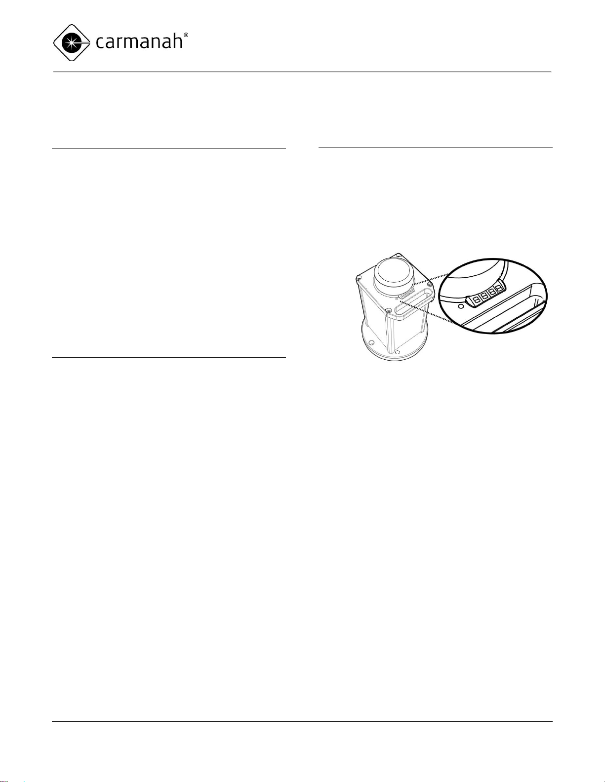
Parts Description...........................................5
Programming the Lantern.............................6
Preparing the Lantern for Installation...................6
Viewing Lantern Settings......................................6
Summary of Lantern States and Statuses ...........7
Using the Infrared (IR) Programmer...................11
Turning the Lantern On or Off............................12
Setting the Flash Character................................13
Setting Effective Intensity...................................13
Setting an Intensity to Comply with Obstruction
Lighting Standards.........................................13
Setting Intensity of Infrared (IR) output..........14
For all other applications:...............................14
Activating/De-activating Automatic Light Control
(ALC)..................................................................14
Setting the Calendar Function............................15
To toggle the Calendar setting on or off: .......15
To set the date that the lantern will enter dated
shutdown:.......................................................15
To set the date the lantern will reactivate: .....15
Editing the Lantern Date and Time (Non-GPS
Units Only)..........................................................16
To edit the lantern date:.................................16
To edit the lantern time:.................................16
Setting Day-to-Night Transition Level ................17
Setting Night-to-Day Transition Level ................17
Enable/Disable Tap-to-Activate LED Display
Option.................................................................18
Viewing Firmware Version..................................18
Enabling Telemetry ............................................18
Setting the Synchronization Function (GPS or
Wired-Sync equipped Lanterns Only) ................19
GPS Status (GPS-equipped Lanterns Only)......19
Installing a Lantern ..................................... 20
Choosing a Suitable Location............................ 20
Adequate Sunlight......................................... 20
External Power Source (M840)..................... 20
Ambient Temperature ................................... 20
Securing the Lantern......................................... 20
Wired-Sync Enabled Lanterns........................... 21
Installing the Bird Deterrent............................... 21
Charging the Lantern (Self-Contained
Only) 22
Sunlight ......................................................... 22
External Power Source ................................. 22
Charge Indicator............................................ 22
Charging via an External Power Source (Quick
Access Charge Port) ......................................... 22
Determining Battery State of Charge (Self-
Contained Only)................................................. 23
Changing the Battery (Self-Contained Only)..... 24
Changing the Battery (12V) (Self-Contained Only)
........................................................................... 26
Preparing the Lantern for Storage (Self-
Contained Only) .......................................... 28
Storage Maintenance/Duration.......................... 28
Warranty and Customer Service................ 29
Warranty............................................................ 29
Additional Products............................................ 29
Customer Service.............................................. 29
Appendix A: Flash Characters..................... 30
Appendix B: Troubleshooting....................... 39

800 series USER MANUAL
INTRODUCTION
4 ©2020 Sabik Marine
Introduction
Applications
The 800 series lantern has the following
applications:
Fixed and floating aids to navigation
Port, marina and dock lighting
Offshore platform marking
Aquaculture
Tower & crane marking
Hazard marking and way-finding
Infrared (IR) lighting for aircraft signaling
Range
The 800 series Lantern is visible from up to
approximately 10 nautical miles (18.5 km) at night
depending on the installation location and selected
flash setting.
Common Features and
Functionality
The 800 series lantern is available as a standalone
or a self-contained, solar powered light with the
following features:
Easily visible, “tap-to-activate” digital LED
display
Latest generation, high-efficiency LEDs and
optics
Simplified installation & setup. No
“transitioning” required prior to installation or
storage.
Rugged polycarbonate and aluminum
enclosure for maximum durability in a
lightweight, economical package
Calendar function available for automatically
de-activating lantern light during off-season
periods
Optional GPS synchronization for setting
any number of lanterns and other Sabik
Marine GPS-equipped lanterns to flash in
unison
Optional Infrared (IR) LED lighting.
Note: IR light is emitted only when device
visible light is turned on.
Optional secure satellite monitoring and
status reporting (M800 lanterns only)

800 series USER MANUAL
PROGRAMMING
5 ©2020 Sabik Marine
Parts Description
Solar panels (self-contained) or
UV-resistant polycarbonate plate
(standalone)
Mounting holes
(3 and 4-bolt patterns)
Bird deterrent
LED display
Visual color
indicator
Optics and lens
Handle
Powder-coated aluminum frame

800 series USER MANUAL
PROGRAMMING
6 ©2020 Sabik Marine
Programming the Lantern
Please thoroughly read these
instructions before proceeding with
the installation.
Preparing the Lantern for
Installation
The 800 series lantern has been designed with a
simplified user experience in mind. Lanterns are
ready for use on shipment and do not have to be
“transitioned” from day to night before making
changes to settings.
Pre-Programmed Lanterns
If Sabik Marine or an authorized distributor has
programmed the lantern prior to you receiving it, it is
ready to install. When the lantern is removed from
the box and exposed to light, it will begin normal
operation, activating with the next day-to-night
transition. Prior to field deployment, verify that the
lantern’s pre-programmed settings match your
requirements using the top-mounted LED display.
Refer to the following section on “Viewing Lantern
Settings” for details. If you have been supplied with
an IR programmer, you may modify lantern settings
prior to installation if desired.
Non-Programmed Lanterns
If you have not requested a pre-programmed
lantern, you will need to verify the lantern settings
(intensity, flash pattern, calendar function & etc.) and
make any required modifications using a Sabik
Marine IR programmer. Refer to the following
sections on “Viewing Lantern Settings” and “Using
the Infrared (IR) Programmer” for details. If you
require a Sabik Marine IR programmer, please
contact Sabik Marine or your authorized distributor.
Viewing Lantern Settings
Quickly Viewing Summary Data
The top-mounted LED Display provides essential
summary information about your lantern. To activate
the LED Display, tap very quickly three times on the
left shoulder or the head of the lantern.
Once activated, the LED Display will show in
sequence:
Lantern Status
Battery State of Charge & Battery Voltage
Lantern Flash Character
Lantern Effective Intensity
Automatic Light Control (ALC) On/Off
Calendar On/Off
Refer to the following page for a detailed description
of these items.
Pressing the button on the IR
programmer will also provide quick
access to this essential summary
information.
Accessing Complete Data via the Infrared (IR)
Programmer
Use the IR programmer to view complete state and
status details, including calendar settings and GPS
settings (if applicable). Using the IR programmer,
you can also customize flash patterns, adjust
calendar settings and more. Refer to the following
table for a complete list of visible and programmable
lantern settings.

800 series USER MANUAL
PROGRAMMING
7 ©2020 Sabik Marine
Summary of Lantern States and Statuses
The following table indicates the data that can be reviewed on the lantern LED Display and, where applicable,
customized via the IR programmer.
Display
Description
Values
Programming
StAt
Lantern Mode
On
The lantern is in standard operating mode and will
automatically transition between “daytime” (LEDs
off) and “evening/night-time” (LEDs on) as ambient
light levels change.
See “Changing
Lantern State”
Off
The lantern is in an energy saving mode with the
LEDs off. The lantern will reactivate with its last
programmed settings only once turned “on” using
the IR programmer and exposed to bright light.
cont
The lantern is in demo mode and will operate
continuously until placed in another operating
mode. Do not field deploy lanterns in continuous
mode.
For distributor and
factory use only. If
the lantern is
unintentionally
displaying one of
these modes,
consult the
troubleshooting
section.
Stor
The lantern is in an energy saving factory storage
mode with Infrared functionality temporarily turned
off.
bAtt
State of Charge
and Battery
Voltage
SoC
Displays the current battery state-of-charge as a
percent value. A value less than 10 indicates that
the lantern LEDs are turned off and Low Voltage
Disconnect (LVD) is engaged.
See “Determining
Battery State of
Charge”
Volt
Indicates the real-time battery voltage
FLSH
Lantern Flash
Character
001-273
Displays the three-digit Flash Character reference
number.
“Setting the Flash
Character.”
Appendix A“
includes a complete
list of available
options.

800 series USER MANUAL
PROGRAMMING
8 ©2020 Sabik Marine
Display
Description
Values
Programming
EInt
Lantern
Effective
Intensity
1-999 cd
The Effective Intensity of the lantern is displayed in
units of candela. This is a measure of the lantern’s
apparent brightness, and is calculated internally
using the Schmidt-Clausen formula. Maximum
effective Intensity may be limited by the Flash
Character selected. Entering a value that is too
high will result in an error message (Err).
See “Setting
Effective Intensity”
ALC
Automatic Light
Control Settings
on
When ALC mode is set to On, the lantern monitors
the battery pack’s state-of-charge and reduces the
intensity level if the lantern is not receiving
sufficient solar energy to maintain the battery pack.
ALC is designed to prolong battery life in the event
of unusually poor weather over an extended period
of time, or excessive bird fouling of the solar panel.
See “Activating/
Deactivating
Automatic Light
Control”
oFF
tEL
Telemetry
Status
CELL
The lantern has a cell modem available. Displays
“on” if enabled, and “oFF” if disabled.
See “Enabling
Telemetry”
Sat
The lantern has a satellite modem available.
Displays “on” if enabled, and “oFF” if disabled.
CAL
Calendar
Enable
on
Indicates if the calendar function is on or off.
See “Setting the
Calendar Function”
oFF
Con
Calendar ON
Date
mon MM
day DD
Indicates the date the lantern will enter a dated
shutdown period. This field is only visible when the
Calendar is enabled.
CoFF
Calendar OFF
Date
mon MM
day DD
Indicates the date the lantern will reactivate at the
end of a dated shutdown period. This field is only
visible when the Calendar is enabled.

800 series USER MANUAL
PROGRAMMING
9 ©2020 Sabik Marine
Display
Description
Values
Programming
date
Date
(displayed on
non-GPS-
equipped units
only)
year
YYYY
mon
MMM
day DD
For units without GPS, this indicates the user-
programmed date or factory-set UTC. In the event
of a battery disconnect, review and, if required, re-
program this value. GPS-equipped units operate
on Coordinated Universal Time (UTC) and this field
is not visible.
See "Editing the
Lantern Date and
Time (Non-GPS
Units Only)”
time
Time
Hour HH
min MM
For units without GPS, this indicates the user-
programmed time or factory-set UTC. In the event
of a battery disconnect, review and, if required, re-
program this value. GPS-equipped units operate
UTC and this field is not visible.
See "Editing the
Lantern Date and
Time (Non-GPS
Units Only)”
gPS
GPS Status
(For GPS-
equipped units
only)
Good
GPS Satellite signal found and locked
See “GPS Status
(GPS-equipped
Lanterns Only)”
PAuS
GPS function paused to conserve energy
SrcH
Searching for GPS satellite signal
nLoC
No lock on GPS satellite signal. Search resumes
every 10 minutes.
SYnC
oFF
No Synchronization configuration
See “Setting the
Synchronization
Function (GPS or
Wired Sync
equipped Lanterns
only)”
GPS
Synchronization
(For GPS-
equipped units
only)
CTC
Sync with other M800 lanterns set to CTC
UTC
Sync with other M800 lanterns set to UTC
CTCL
Sync with legacy 700 series lanterns
Wired-Sync (For
wired-sync
equipped units
only)
CBL1
Wired-Sync Secondary
CBL2
Wired-Sync Primary (use only if no other primary in
wired-sync network)
d2n
Day to Night
Transition Level
(D2N)
025L-
400L
Indicates the ambient brightness (in lux) at which
the lantern LEDs will turn on in the evening.
See “Setting Day to
Night Transition
Level”

800 series USER MANUAL
PROGRAMMING
10 ©2020 Sabik Marine
Display
Description
Values
Programming
n2d
Night to Day
Transition Level
(N2D)
075L-
450L
Indicates the ambient brightness (in lux) at which
the lantern LEDS will turn off in the morning.
See “Setting Night
to Day Transition
Level”
info
Firmware
Version
1.x.x.x
Displays the current firmware version. This value
may be used by the manufacturer for
troubleshooting purposes.
See “Viewing
Firmware Version”
SrcE
Charge Source
Int
The lantern is being charged by the internal solar
panels or connected to an external source (M840)
See “Charging the
Lantern”
oPtn
The lantern’s batteries are being charged by a wall
charger or other external source.
tAP
Tap-to-Activate
Enable
on
Turns on or off the “tap-to-activate” functionality of
the LED display if desired. Once turned off, an
Infrared (IR) programmer is required to view
lantern state and status.
See
“Enable/Disable
Tap-to-Activate
LED Display
Option”
oFF
.
Charging
The lower right decimal point on the LED display
will flash regularly to indicate that the lantern is
charging. (Does not occur for the M840)
See “Charging the
Lantern”

800 series USER MANUAL
PROGRAMMING
11 ©2020 Sabik Marine
Using the Infrared (IR)
Programmer
All functions of the 800 series lantern are controlled
by the IR programmer.
Important User Notes
The IR programmer uses one
CR2025 battery (shipped with unit).
Remove the battery tab from the
back of the IR programmer on first
use.
Keep a minimum distance of 6” (15
cm) between the IR programmer
and the lantern.
The Lantern must be in “on” mode
to change settings using the IR
programmer. If a Lantern is in “off”
mode, you may review settings
using the key, but you will not
be able to scroll through detailed
information or program the lantern.
The IR programmer includes the following keys:
The power key awakens the infrared
sensor inside the lantern and allows
the unit to accept programming
commands.
To conserve power, the 800 series
lantern searches for an Infrared
signal on a 0.5 second cycle. You
may need to press the power key
multiple times to establish a
connection. Typically, three steady
button presses will be sufficient;
however, you may need to make
more or fewer connection attempts
to coincide with the lantern signal.
The lantern LEDs will flash to
confirm that a connection has been
made. Once a connection has been
made, all IR commands will be
received and confirmed with a flash.
If no IR signals are received within
60 seconds, the IR receiver will
switch back to power saving mode.
The information key provides quick
access to Lantern Status, Battery
State of Charge & Battery Voltage,
Lantern Flash Character, Lantern
Effective Intensity, Automatic Light
Control (ALC) setting, and Calendar
On/Off.
Use the up/down arrow keys to
scroll easily through the LED Display
values.
The left/right arrow keys are used to
navigate away from a selected menu
item, or to move between digits
when programming a setting.
Use the number keys to directly
enter numeric values.
The (A) key allows jumps directly to
the Flash Character menu to view or
edit Flash Character settings.
The (B) key jumps directly to the
Lantern Effective Intensity menu to
view or edit Effective Intensity.

800 series USER MANUAL
PROGRAMMING
12 ©2020 Sabik Marine
The set button unlocks and locks
settings. Press this button to change
a displayed value (editable settings
only) and to lock in an updated
value. When a new value is locked,
the lantern LEDs and the LED
display will flash three times to
confirm that the new settings have
been registered and are active. If a
value is entered that is outside of the
lantern’s acceptable parameters
then “Err”(error) is displayed, the
LEDs will flash two times, and the
lantern will revert to the previous
setting.
Turning the Lantern On or Off
The 800 series lantern can be switched into the
following two basic operating modes:
On:The lantern is in standard operating
mode and will automatically transition
between “daytime” (LEDs off) and
“evening/night-time” (LEDs on) as ambient
light levels change.
Off: The lantern is in an energy saving
mode with the LEDs off. The lantern will
reactivate with its last programmed settings
only once turned “on” using the IR
programmer and exposed to bright light.
An additional “Continuous” mode is also available on
distributor demo units. Contact
customerservice@flashtechnology.com for the
activation code for this mode. To exit continuous
mode select On or Off in the Stat menu.
To turn the lantern on or off:
1. If you have not already done so,
establish a connection to the lantern.
2. The lantern LEDs will flash to confirm
the lantern is ready to receive
commands.
3. Press and hold the power button for
approximately five seconds until the
LED display changes to show “stAt
On” or “byE”.

800 series USER MANUAL
PROGRAMMING
13 ©2020 Sabik Marine
Setting the Flash Character
A complete list of available Flash Characters is
provided in Appendix A.
1. If you have not already done so,
establish a connection to the
lantern.
2. The lantern LEDs will flash to
confirm the lantern is ready to
receive commands.
or
3. Navigate to the FLSH menu or
press the (A) button to jump directly
to this function
4. Unlock the existing setting
5. Use the number keys to direct enter
the desired Flash Character (see
Appendix A).
6. Lock the new setting
7. The lantern LEDs will flash to
confirm that the new setting has
been locked.
The 800 series has intelligent
settings to prevent the lantern from
operating with certain Flash
Character and Effective Intensity
combinations. Effective Intensity
may be automatically lowered when
you change Flash Characters.
ALWAYS review Effective Intensity
after changing Flash Characters.
Setting Effective Intensity
The Effective Intensity of the lantern is a measure of
its apparent brightness in candela. It takes into
account the reduction from peak intensity caused by
the Schmidt Clausen factor.
Setting an Intensity to Comply with
Obstruction Lighting Standards
Users of the M80xx Series Lanterns may wish to
program the light to meet a specific Obstruction
Lighting specification.
If you have not already done so,
establish a connection to the lantern.
The lantern LEDs will flash to confirm the
lantern is ready to receive commands.
Specification
Enter Key
Sequence
FAA L-810 (AC 150/5345-43,
EB67)
6-3-3
ICAO Type A (Annex 14, Vol. 1,
5th Ed./2009)
6-1-3
ICAO Type A (Annex 14, Vol. 1,
6th Ed./2013)
6-2-3
ICAO Type B (Annex 14, Vol. 1
5th Ed./2009)
6-4-1
ICAO Type B (Annex 14, Vol. 1,
6th Ed./2013)
6-7-2
CASA 10 cd (Part 133, Vol. 2)*
6-1-3
Transport Canada CD-810 (Std.
621)
6-6-6
* Code 613 satisfies the requirements of both CASA 10cd and
ICAO Type A (Annex 14, Vol. 1, 5th Ed./2009).

800 series USER MANUAL
PROGRAMMING
14 ©2020 Sabik Marine
Setting Intensity of Infrared (IR) output
The intensity of the IR output is linearly proportional
to the effective intensity setting. The higher the
effective intensity, the more intense the
simultaneous intensity of IR. At 33cd effective
intensity, the IR output is 0.4 mW/St peak.
For all other applications:
1. If you have not already done so,
establish a connection to the lantern.
2. The lantern LEDs will flash to confirm
the lantern is ready to receive
commands.
or
3. Navigate to the EInt menu or press
the (B) button to jump directly to this
function
4. Unlock the existing setting
5. Use the number keys to direct enter
the desired Effective Intensity.
6. Lock the new setting
7. The lantern LEDs will flash to confirm
that the new setting has been locked.
The 800 series has intelligent
settings to prevent the lantern from
running with certain Flash
Character and Effective Intensity
combinations. You may receive an
error (Err) message if you are
attempting to enter a value that is
not compatible with your
programmed Flash Character.
Choose a lower value or modify
your Flash Character to resolve
this issue.
Activating/De-activating Automatic
Light Control (ALC)
When ALC mode is set to “on”, the lantern monitors
the battery pack’s state of health and reduces the
intensity level if there is insufficient solar energy to
maintain the battery pack.
1. If you have not already done so,
establish a connection to the
lantern.
2. The lantern LEDs will flash to
confirm the lantern is ready to
receive commands.
3. Navigate to the ALC menu
4. Unlock the existing setting
5. Toggle between “on” and “off”
6. Lock the new setting
7. The lantern LEDs will flash to
confirm that the new setting has
been locked.
To quickly change ALC settings,
you may direct enter one of the
following quick access codes:
8-0-1 (to activate)
8-0-0 (to deactivate)
When ALC intervenes, the LEDs
brightness is reduced. Set the ALC
to off if your application demands
that the lantern meets specific
intensity requirements at all times.

800 series USER MANUAL
PROGRAMMING
15 ©2020 Sabik Marine
Setting the Calendar Function
The Calendar Function allows you to specify a dated
shutdown if desired.
GPS-enabled lanterns will be
synched to Coordinated Universal
Time (UTC). For units without
GPS, check the LED Display for
the current date and time and, if
required, update the date setting
prior to programming the calendar
function.
To toggle the Calendar setting on or off:
1. If you have not already done so,
establish a connection to the lantern.
2. The lantern LEDs will flash to confirm
the lantern is ready to receive
commands.
3. Navigate to the CAL menu.
4. Unlock the existing setting
5. Toggle between “on” and “off
6. Lock the new setting
7. The lantern LEDs will flash to confirm
that the new setting has been locked.
To set the date that the lantern will enter
dated shutdown:
Confirm that the Calendar is turned “on”.
1. Navigate to the Con menu
2. Scroll to the Month value (ΠΠon)
3. Unlock the existing setting
4. Use the number keys to enter the
month when dated shutdown will
begin.
5. Lock the new setting
6. Scroll to the day value (dAY)
7. Use the number keys to enter the
specific day of the month when
dated shutdown will begin.
8. Lock the new setting
9. The lantern LEDs will flash to
confirm that the new setting has
been locked.
To set the date the lantern will reactivate:
Confirm that the Calendar is turned “on”.
1. Navigate to the CoFF menu
2. Scroll to the Month value (ΠΠon)
3. Unlock the existing setting
4. Use the number keys to enter the
month when dated shutdown will
end.
5. Lock the new setting
6. Scroll to the day value (dAY)
7. Use the number keys to enter the
specific day of the month when
dated shutdown will end.
8. Lock the new setting
9. The lantern LEDs will flash to
confirm your change.

800 series USER MANUAL
PROGRAMMING
16 ©2020 Sabik Marine
Editing the Lantern Date and Time
(Non-GPS Units Only)
Lantern Date and Time are used for data logging
and for controlling the calendar function. The 800
series lantern (without GPS) has an internal clock
which it uses for logging activity. The lantern will be
factory programmed in Coordinated Universal Time
(UTC). You may re-program the lantern to local date
and time if desired. In the event that the lantern
battery pack is disconnected, verify the date settings
and reset if required.
GPS-equipped units will be
synchronized to Coordinated
Universal Time (UTC). The
date/time settings on GPS-
equipped units cannot be modified.
To edit the lantern date:
1. If you have not already done so,
establish a connection to the
lantern.
2. The lantern LEDs will flash to
confirm the lantern is ready to
receive commands.
3. Navigate to the date menu
4. Scroll to the Month value (ΠΠon)
5. Unlock the existing setting
6. Use the number keys to enter the
current month.
7. Lock the new setting
8. Scroll to the Day value (dAY)
9. Use the number keys to enter the
current day.
10. Lock the new setting
The lantern LEDs will flash to confirm
that the new setting has been locked.
To edit the lantern time:
1. If you have not already done so,
establish a connection to the
lantern.
2. The lantern LEDs will flash to
confirm the lantern is ready to
receive commands.
3. Navigate to the Time menu
4. Scroll to the hour value (HH)
5. Unlock the existing setting
6. Use the number keys to enter the
current hour (24-hour clock).
7. Lock the new setting
8. Scroll to the minute value (MM)
9. Use the number keys to enter the
current minute
10. Lock the new setting
11. The lantern LEDs will flash to
confirm that the new setting has
been locked.

800 series USER MANUAL
PROGRAMMING
17 ©2020 Sabik Marine
Setting Day-to-Night Transition
Level
The Day to Night Transition level (D2N) is the
ambient brightness (in lux), at which the lantern’s
LEDs will turn on in the evening. A higher value for
the D2N Transition level causes the LEDs to turn on
earlier; a lower value causes it to turn on later.
Remember that the earlier the
lantern turns on, the more battery
power it consumes. Therefore,
higher D2N Transition Level
settings lower the Effective
Intensity Limit and Projected
Autonomy slightly.
To set the D2N Transition Level (between 025 and
400L):
1. If you have not already done so,
establish a connection to the lantern.
2. The lantern LEDs will flash to confirm
the lantern is ready to receive
commands.
3. Navigate to the D2N menu
4. Unlock the existing setting
5. Use the number keys to enter a
value in lux. Once programmed, the
lantern LEDs will turn on when
ambient brightness decreases to this
lux value.
6. Lock the new setting
7. The lantern LEDs will flash to confirm
that the new setting has been locked.
Setting Night-to-Day Transition
Level
As the sun rises, the ambient light level goes up.
The night to day level (N2D) is the ambient light
level (in lux) at which the lantern’s LEDs turns off in
the morning. A lower N2D turns the LEDs off earlier
in the day.
The later the lantern turns off, the
more battery power it consumes.
Therefore, higher N2D Transition
Level settings lower the Effective
Intensity Limit and Projected
Autonomy slightly.
To set the N2D Transition Level (between 075 and
450L):
1. If you have not already done so,
establish a connection to the lantern.
2. The lantern LEDs will flash to
confirm the lantern is ready to
receive commands.
3. Navigate to the N2D menu
4. Unlock the existing setting
5. Use the number keys to enter a
value in lux. Once programmed, the
lantern LEDs will turn off when
ambient brightness increases to this
lux value.
6. Lock the new setting
7. The lantern LEDs will flash to
confirm that the new setting has
been locked.
The N2D Transition Level must be at
least 50L greater than the D2N
Transition Level. The D2N level will be
automatically adjusted if required.

800 series USER MANUAL
PROGRAMMING
18 ©2020 Sabik Marine
Enable/Disable Tap-to-Activate
LED Display Option
With Tap-to-Activate enabled, a quick triple tap on
the left shoulder or head of the lantern will activate
the LED Display to list the lantern’s status, battery
state of charge & voltage, Flash Character, Effective
Intensity, ALC On/Off, and Calendar On/Off. In some
locations where the lantern may be subject to
extreme movement or jostling, this function may be
disabled to minimize power consumption from
unintentional activation of the LED Display.
To toggle this setting:
1. If you have not already done so,
establish a connection to the lantern.
2. The lantern LEDs will flash to confirm
the lantern is ready to receive
commands.
3. Navigate to the tAP menu.
4. Unlock the existing setting
5. Toggle between “on” and “off”
6. Lock the new setting
7. The lantern LEDs will flash to confirm
that the new setting has been locked.
Viewing Firmware Version
To determine your firmware version:
1. If you have not already done so,
establish a connection to the lantern.
2. The lantern LEDs will flash to confirm
the lantern is ready to receive
commands.
3. Navigate to the info menu. The 4-
digit firmware version will scroll in
from the right.
Enabling Telemetry
If so equipped, users will have to enable the
telemetry setting on their lantern with the IR
programmer prior to deploying it in the field.
1. If you have not already done so,
establish a connection to the lantern.
2. The lantern LEDs will flash to confirm
the lantern is ready to receive
commands.
Specification
Enter Key Sequence
Enable Telemetry
7-2-8-1
Disable Telemetry
7-2-8-0
The lantern LEDs will flash to confirm that the new
setting has been programmed.

800 series USER MANUAL
PROGRAMMING
19 ©2020 Sabik Marine
Setting the Synchronization
Function (GPS or Wired-Sync
equipped Lanterns Only)
To enable GPS synchronization between M800
series lanterns, SYnC must be configured to the
same setting on all units, either “CTC” (proprietary
time), “UTC” (UTC time) or “CTCL” (legacy lanterns).
Once activated, GPS-equipped lanterns
automatically synchronize with GPS-equipped
lanterns set to the same flash character; however, it
can take several minutes for lanterns to synchronize.
The synchronization period is dependent on the
number of satellites overhead and any obstructions
from buildings or mountainous terrain.
For Wired synchronization functionality, there must
be only one primary on the wired-sync network. If no
other primary is connected, set SYnC on one M800
lantern to “CBL2” (wired sync primary) and all other
lanterns to “CBL1” (wired sync secondary).
The date/time settings on GPS-
equipped units cannot be modified.
To select the Synchronization function:
1. If you have not already done so,
establish a connection to the lantern.
2. The lantern LEDs will flash to confirm
the lantern is ready to receive
commands.
3. Navigate to the SYnC menu.
4. Unlock the existing setting
5. Scroll to the desired setting “off”,
“CTC”, “UTC”, “CTCL”, “CBL1”, or
“CBL2”.
6. Lock the new setting
7. The lantern LEDs will flash to confirm
that the new setting has been locked.
GPS Status (GPS-equipped
Lanterns Only)
GPS-equipped lanterns have the following four
additional status flags:
Good: GPS Satellite signal found and locked
PAuS: GPS function has been paused to
conserve energy. This will occur when GPS
function is not in use; for example, when the
lantern is in “stead-on” mode (flash code
001), or when the lantern is in dated shutdown.
SrcH: The GPS unit is searching for a satellite
signal
nLoC: The unit was unable to find and lock a
GPS satellite signal. Search will resume every
10 minutes at night and every 45 minutes during
the day until a signal is found.
To determine GPS state:
1. If you have not already done so,
establish a connection to the lantern.
2. The lantern LEDs will flash to confirm
the lantern is ready to receive
commands.
3. Navigate to the gPS menu. The GPS
state will scroll in from the right.

M850/M860 USER MANUAL
CHARGING
20 ©2020 Sabik Marine
Installing a Lantern
Choosing a Suitable Location
Adequate sunlight and suitable ambient temperature
are the two most important factors to consider when
choosing a location for Sabik Marine solar lanterns.
Adequate Sunlight
Most of the 800 series lanterns are powered by solar
energy stored inside the rechargeable batteries of
the lantern; therefore, to operate each night they
require an adequate amount of sunlight to recharge
their batteries. The following factors should be
considered when installing the lanterns:
the amount of sunlight available in the region
an unobstructed view of the sun (the lantern
should not be shaded)
seasonal changes in sun angle
External Power Source (M840)
The M840 lantern is designed without internal
batteries or integrated solar panels to allow
customers a way to add their own external power
source.
It is supplied with a two-wire UV-rated external
cable, approximately 10 feet in length, with labeled
and numbered conductors for DC IN + (positive) and
DC IN - (negative).
The input range of the DC IN is 9V-32V and it is
current-limited to 2.5A. An external source applied to
this input should be capable of supplying 2.5A or
more.
Ambient Temperature
The temperature range of the lantern location must
be between -40 to 176 °F (-40 to 80 °C).
Securing the Lantern
Physically modifying the 800 series
lantern will void the warranty. This
includes drilling additional holes in
the base or re-drilling the existing
mounting holes to a larger diameter.
The lantern base plate has six mounting holes
intended for three or four-point mounting patterns.
The use of security fasteners is recommended to
prevent theft. Use 18-8 stainless steel hex head
fasteners with ½ -13 UNC thread. Tighten the
fasteners to 40 to 44 ft-lbs (4.5 to 5.0 N·m).
Table of contents