Studio Titan STA 01-350R-MK2 User manual

STA 01-350R-MK2 (Rotaon) series 1
CAUTION: Use supplied leather work gloves and safety glasses when handling the box,
when opening the box and when assembling the product.
HAZARD: Strapping is under tension and can jump when cut. Strapping and Buckles,
rotective Edging, lastic Walls, lastic Caps and roduct Components and parts should be
handled with care. Work slowly, use extra caution to avoid any sharp edges.
Additional Tools may be Required: The essential tools are included. The following tools
are recommended to be on site: Box Cutter, Scissors, Screw Driver, lyers or Adjustable
wrench, Metric Hex / Allen Key set

STA 01-350R-MK2 (Rotaon) series 2
Transit Damage:
Each package is inspected prior to being shipped from the
warehouse to insure that is in perfect condition. The column
shipping boxes are constructed using extra thick cardboard.
Some packaging includes engineered plastic walls, end caps
and banding. The columns are packed using engineered plas-
tic walls and in dense foam to protect and absorb energy
from reasonable drops and impacts. The column packaging is
designed and drop tested from approximately 5 feet [ .5 Me-
ters] without sustaining any internal damage. The packaging
is crush tested using a 660lb [300kg] weight placed along the
long side of the box without sustaining any internal damage.
If handled without care the boxes will show signs of transit
damage. Wearing supplied work Gloves, while following the
Assembly Steps, carefully inspect the contents inside the box-
es. Specifically the Vertical center column top cap pulley
should be securely fastened to the top of the Vertical center
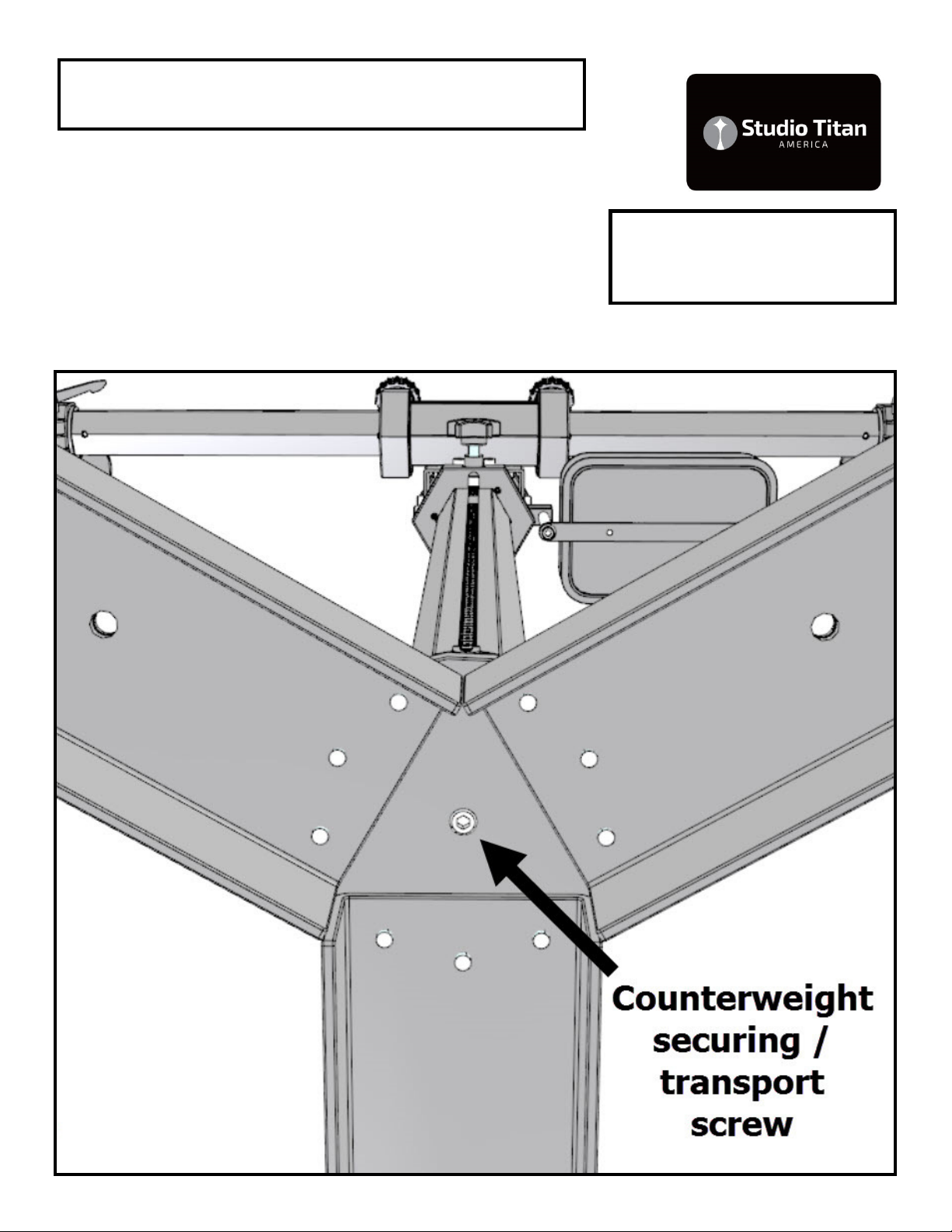
column as shown on the [component identification] page. In
the base, the transportation counterweight securing strap
should be secured to the counterweight. [See Diagram: E] If
anything seems unusual, !!!STOP!!! Send images to: in-
[email protected] for a second opinion. If there are
damaged OR Loose parts, do not assemble the stand, you
may injure yourself. If the damage is noticeable such as
cracks or loose or broken parts contact your dealer for ex-
change. If the damage is minor or cosmetic and does not
compromise the safe assembly or operation of the stand send
images of the parts that are affected to:
[email protected]. Arrangements will be made to
provide you with replacement parts to restore the stand to
new condition.

STA 01-350R-MK2 (Rotaon) series 3
Product Identification:
Product Nameplate Label is located on the vertical column assembly.
The label information is indicated below:
STUDIO TITAN AMERICA
No.[Model Num er] - [Manufacture Date]
Imported y / Importe par
STEPHANIE MCNEIL CORPORATION
250 Augusta Ave, Suite 204
Toronto, ON M5T 2L7 CANADA
Manufactured in / Fa rique en
SOUTH KOREA
Label examples are indicated below:

STA 01-350R-MK2 (Rotaon) series 4
Intended use:
This product is intended for use by professional
and commercial photographers in a studio envi-
ronment with a high ceiling. The wheels are
designed to be used indoors on a floor that is
smooth, hard, flat and unobstructed. The Studio
Stands with internal counterweight are designed
to be used at all times with a load (Camera or
laptop shelf or both). CAUTION: This product
is not recommended for use by hobbyists or in a
household environment with a low ceiling or
carpeted floors. Carpeting or pitted surfaces are
not recommended because of the increased roll-
ing resistance which can cause the stand to tip
over. If the surface is not ideal, the stand must
be moved with CAUTION, very slowly, using
both hands one at the top and the other at the
bottom to steady the stand in order to prevent
the stand from tipping over. If the surface is not
ideal, lower the load to waist level before mov-
ing the stand. We also recommend the use of a
sandbag or weight attached at the base when
conditions are not ideal to prevent tipping over.
Ultimately it’s the users responsibility to under-
stand how the stand operates and to use the
stand within its specification limits, as intended
to insure their own safety and the safety of
their equipment. It is also recommended to use
a short tether cable to secure the camera to the
stand in the event that the head, head plate,
attachment stud or camera adapter plate comes
loose or fails. Some assembly is required, we
recommend using an assistant during the initial
product assembly. Please read all documenta-
tion prior to assembly.

STA 01-350R-MK2 (Rotaon) series 5
Component Identification: STA 01-3 0R-MK2
STA 01-350R-MK2 (Rotaon) series 6
Component Identification: STA 01-3 0R-MK2

STA 01-350R-MK2 (Rotaon) series 7
! CAUTION ! Cross Threading Components:
Cross-threading components during assembly is not covered under war-
ranty.
Cross-threading is a term that describes damage that is caused when a
misaligned screw or knob thread is forced into a threaded hole. When this
occurs, threads are damaged and are no longer capable of proper opera-
tion. The remedy is replacement or repair of the damaged component/s.
AVOID cross-threading of mounting screws and knobs during assembly us-
ing this easy to follow procedure:
While standing in front of and looking into the threaded hole. Place the
screw or knob thread against the threaded hole. Using one hand, hold the
thread between your fingers. With the other hand hold the hex key like a
pencil or place your index finger in the center of the knob. Align the screw
or knob with the hole as indicated in the picture with the checkmark be-
low. Slowly turn it counter-clockwise or left, several turns, until you hear a
click or feel the start of the thread. Then proceed slowly, turning clockwise
or right, gently using only finger force to tighten the screw or knob. If you
feel increased resistance, the threads are not aligned, remove and start
procedure from the beginning again.
STA 01-350R-MK2 (Rotaon) series 8
Component Identification: STA 01-3 0R-MK2
Securing / Transport
Screw

STA 01-350R-MK2 (Rotaon) series 9
Component Identification: STA 01-3 0R-MK2
HD Interface Plate

STA 01-350R-MK2 (Rotaon) series 10
Component Identification: STA 01-3 0R-MK2
Hand Lever adjustable, 360 degree
range of movement, camera head
mount plates
STA 01-350R-MK2 (Rotaon) series 11
Assembly Steps:
. Wearing gloves and together with your Assis-
tant……..Place the Column Box [long rectangular
box] flat on floor. Place some packing materials
on the floor. Do not stand the Vertical/Center
Column vertically. Remove and Lay the Vertical/
Center Column flat on the floor. Under the Base,
Visually inspect and Confirm that the Counter-
weight transport securing SCREW is present
which secures the counterweight during transpor-
tation. Do NOT remove the Counterweight
transport securing SCREW until advised later.
Confirm the bolt is present and proceed to step 2
with assembly. If NOT, then:
If Counterweight transport securing SCREW is
NOT present, the counter weight is loose and can
move inside the column. Do not stand the column
vertically. Stop the SET-UP and Contact STEPHA-
NIE MCNEIL CORPORATION for further instruc-
tions. Please email:
info@studiotitanamerica.com with the best phone
number to reach you. We normally respond with-
in 24hrs, during weekdays.
STA 01-350R-MK2 (Rotaon) series 12
Assembly Steps:
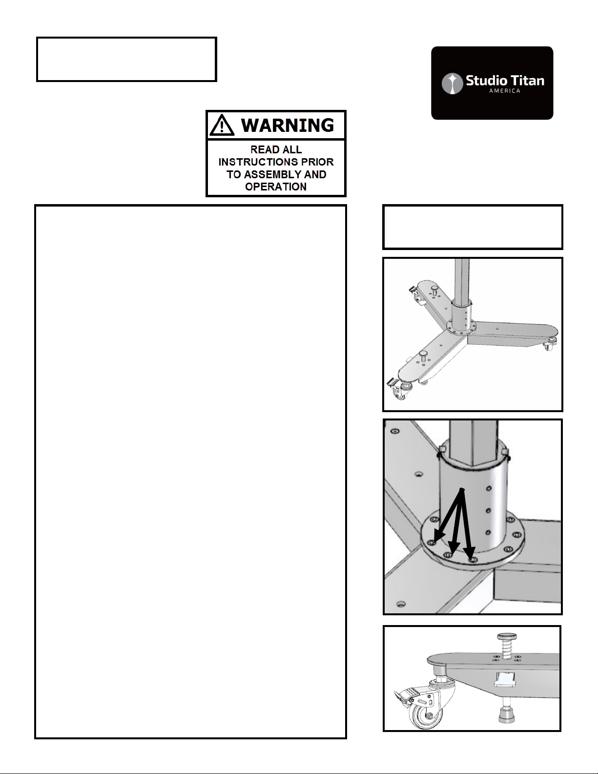
2. Attach the three Leg Assemblies to the base.
[See Diagram: A] The Hex Key tool is supplied
and three fasteners are supplied attached to each
Leg Assembly. Use the supplied Hex Key tool to
tighten the nine fasteners by hand.
Note: two of the leg assemblies are supplied with
foot plungers. To have direct access to the foot
plungers you will want to install the foot plungers
facing the operator or on the same side of the
stand that the Horizontal and Vertical scales face.
3. Wearing Gloves, remove the counterweight
transportation securing SCREW [See Component
Identification STA 0 -350R Diagram ]
4. Locate and identify the counterweight cable.
[See Component Identification STA 0 -350R Dia-
gram ]
!!!CAUTION!!! AVOID CONTACT WITH THE
COUNTERWEIGHT CABLE AT ALL TIMES. CAU-
TION MUST USED TO AVOID PINCHING YOUR
FINGER DURING SET-UP AND NORMAL OPERA-
TION. The counterweight cable may become
frayed during transportation or normal use. When
frayed, stop using the stand and immediately re-
place the cable. Cable strands that separate may
become sharp.
Diagram: A
STA 01-350R-MK2 (Rotaon) series 13
Assembly Steps:
5. Together with your Assistant…Wearing Gloves
…..Carefully, Slowly raise and lift the Vertical/
Center Column until it is standing freely on its
wheels.
6. Locate the M8 Hex Wrench. Refer to section
“Cross Threading Components.” Remove the six
M8 x 20 screws from the Vertical carriage. Two
M8 screws from the front and two from each side.
[Diagram's: B &B2 indicate the screw locations]
Locate the Horizontal Arm/Bar Carriage Assembly.
[See Component Identification STA 0 -350R Dia-
gram] Together with your assistant. Have your
assistant hold the Horizontal Arm/Bar Carriage As-
sembly in place while you fasten it with the six M8
x 20 screws. Note the order. [screw, spring washer
and then flat washer] Hand tightening with the
Hex Wrench is recommended. If you have a
torque wrench tighten the M8 screws to 45Nm or
33 lb/ft. not more.
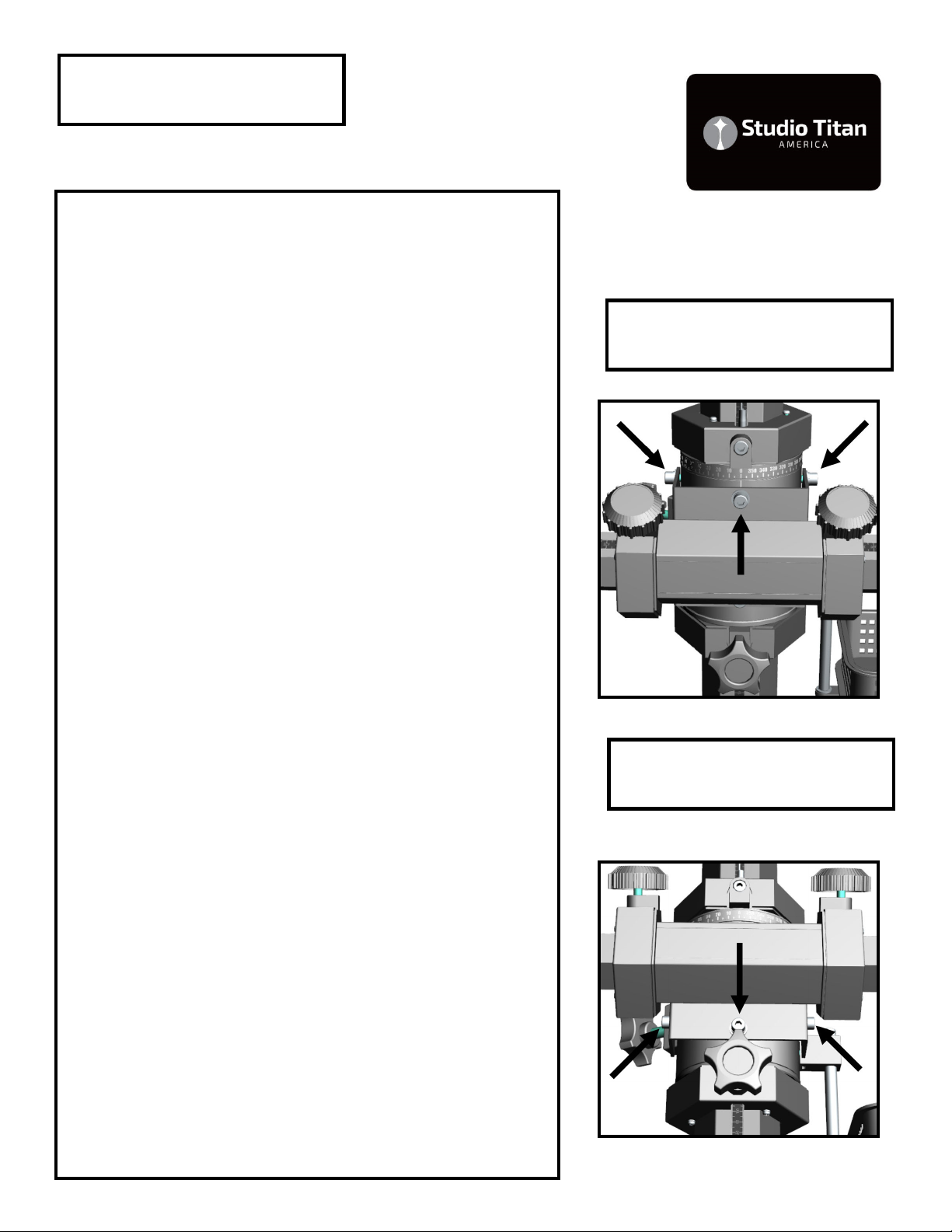
7. Locate the M6 Hex Wrench. Refer to section
“Cross Threading Components.” Locate the loose
Vertical / Brake Knob. Find the Location of the
Vertical Carriage / Brake Knob Transportation Set
Screw. [See DIAGRAM: D]. With the M6 Hex
Wrench FIRST Remove the transportation set
screw and THEN replace with Vertical Carriage /
Brake Knob. Turn the Vertical Carriage /Brake
Knob fully Clock Wise to secure the vertical car-
riage in the upper most or “parking position.”
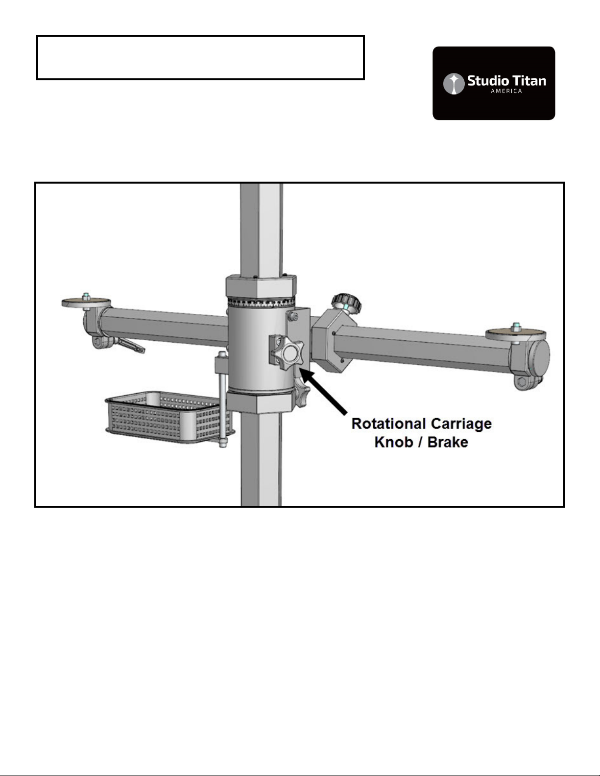
Locate the loose Rotational Knob / Brake. Refer to
section “Cross Threading Components.” Insert and
fasten the Rotational Knob / Brake into the Rota-
tional carriage. [See DIAGRAM: E]
Diagram: B1
Diagram: B2

STA 01-350R-MK2 (Rotaon) series 14
Component Identification: STA 01-3 0R-MK2
Diagram: D

STA 01-350R-MK2 (Rotaon) series 15
Component Identification: STA 01-3 0R-MK2
Diagram: E
STA 01-350R-MK2 (Rotaon) series 16
Assembly Steps:
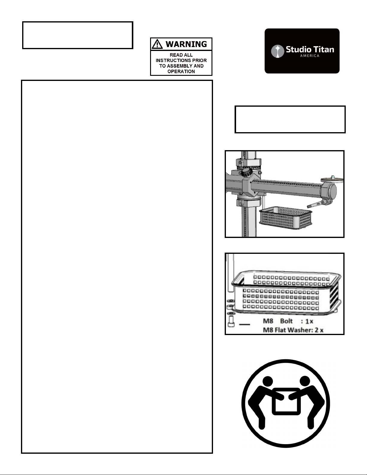
8. Locate two M8 Hex wrenches. Locate the Bas-
ket. Locate the Basket Shaft. [See Component
Identification STA 0 -350R Diagram] Refer to
section “Cross Threading Components.” With the
first M8 hex key hold the M8 screw at the top of
the Basket shaft. With the second M8 hex key
loosen the M8 screw at the bottom of the Basket
shaft. Attach the Basket to the Basket Shaft.
Note the order of fastener connection: [Screw ,
Flat washer, Basket Plate, Flat Washer]. [See: DI-
AGRAM: C]
9. CAUTION: [Only with the Horizontal Arm/Bar in
the upper most positon “parking position”.] Slowly
release the Vertical Carriage Knob/brake by turn-
ing it Counter Clock Wise. This will release the
vertical carriage allowing it to travel freely up and
down the Vertical Center / Colum. Confirm that
the Vertical Carriage is free to move in both direc-
tions while using both hands to hold the Horizon-
tal Arm/Bar. Turn the Vertical Carriage Knob/brake
fully Clock Wise to secure the vertical carriage.
0. Locate the Two Horizontal Carriage Knob/
Brakes. [See Component Identification STA 0 -
350R Diagram] Turn the Horizontal Carriage
Knob/Brake Counter Clockwise to release and
confirm that the Horizontal Arm / Bar is free to
move left and right.
STOP SET-UP— Read below— GO TO STEP If
anything seems unusual or if the vertical carriage
is not moving freely up or down. Stop Set-up and
send a few images of the stand to:
info@studiotitanamerica.com for assistance.
Diagram: C

STA 01-350R-MK2 (Rotaon) series 17
Use & Maintenance Steps:
. HAZARD: Stop and take a moment to under-
stand the effect of the counterweight. HAZARD:
The counterweight forces the vertical column to
travel towards the top of the Studio Stand. With-
out a load [Camera, laptop, etc.] on the horizontal
Arm/Bar it travels towards the top of the stand.
HAZARD: Use the stand with a load [Camera, lap-
top, etc.]. Always securely “Park” the Vertical
Carriage by Turning the Vertical Carriage Knob/
brake fully Clock Wise before and after re-
positioning or before the stand is unloaded
[removing Camera, laptop, etc.].
2. HAZARD: Work in such a way so your always
standing behind or in front of the stand. Keep
clear of the Horizontal Arm/Bar and accessories.
Take extra notice of your body position when you
are releasing the Vertical Carriage Knob/brake.
With your free hand apply a downward force to
the Horizontal Arm/Bar Simultaneously as you re-
lease the Vertical Carriage Knob/brake.
3. Storage: When not in use, store with Vertical
Carriage in the upper most “Parking Position”. Re-
view this manual with all Studio personnel prior to
operating the Studio Stand.
4. Re-tighten all fasteners AGAIN. Re-tighten
fasteners after the first shoot. Tighten yearly.

STA 01-350R-MK2 (Rotaon) series 18
Theory of Operation:
A studio stand is used by professional and commer-
cial photographers to capture images accurately
with repeatability. It provides a rigid and stable
platform essential for High Resolution Sensors used
in DSLR, Medium Format and Large Format camer-
as and imaging systems. A studio stand reduces vi-
brations that are present when shooting hand held.
Reduced vibration increases image sharpness. It
enables the photographer to focus on subject mat-
ter and image composition instead of hand holding
the camera. It provides creative shooting options
using heights and angles that are unachievable
when hand holding a camera. It provides the
foundation stone that enables the photographer to
develop their own technical workflow. As the work-
flow evolves to include advanced imaging practices,
the results can be seen as sharper images.
With an adjustable camera head the user can accu-
rately set up the camera to maintain camera to
subject flatness of field in both the vertical and hor-
izontal planes of travel. The flatness of field is
maintained as the user moves the stand both verti-
cally and horizontally eliminating perspective distor-
tion.
Shooting tethered with an optional accessory / lap-
top shelf, reduces floor cabling and allows the pho-
tographer to immediately confirm both focus and
lighting. A Studio Stand reduces user fatigue. The
internal counter balance offsets the weight of the
camera and computer. Allowing the user to easily
move the camera and computer up and down and
left and right using only one hand. This promotes
good body ergonomics which can prevent tennis
elbow.
STA 01-350R-MK2 (Rotaon) series 19
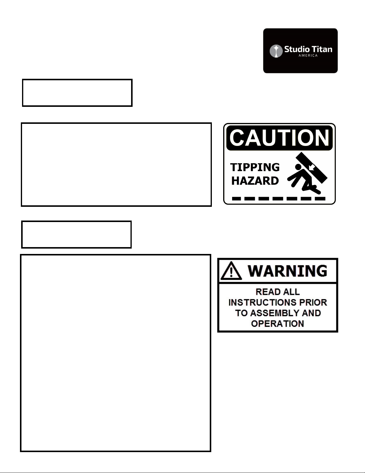
Tip Over Hazard:
Caution must be used when moving the stand to
prevent tip over. Move the stand slowly and avoid
uneven surfaces as well as low and high level ob-
jects. Additional caution must be used when the
Horizontal arm with load (Camera or Laptop
Shelf) is used in the upper area above the mid-
point of the stand.
Counterweight Hazard:
The Horizontal Arm/Bar is connected to a coun-
terweight located inside the Vertical Center/
Column. Caution must be used at all times when
using the Horizontal Arm/Bar. The Vertical Car-
riage Knob/Brake must always be tightened to
lock the Horizontal Arm/Bar in place. Without a
load on the Horizontal Arm/Bar it can travel up-
wards. When releasing the Vertical Carriage
Knob/Brake stand clear of the arms path of move-
ment, firmly hold the Horizontal Arm/Bar applying
pressure downwards. Stand back to avoid contact
with the Horizontal Arm/Bar when unloaded. Do
not remove the load when the Vertical Carriage
Knob/Brake knob is released or turned
CCW. Unless repositioning the Vertical Center/
Column intentionally the Vertical Carriage Knob/
Brake must be fully engaged (turned fully clock-
wise). Store with Vertical Carriage in the upper
most “Parking Position.”
STA 01-350R-MK2 (Rotaon) series 20
STA 01-350R-MK2 Specification & Direc-
tions for Materials Recycling
•Total Height :240cm / 94.4 in **
•Working Height Maximum :220cm / 86.6 in (measured
from Camera late to floor)
•Working Height Minimum :50cm / 19.7 in (measured from
Camera late to floor)
•Rotational Range of Horizontal Bar: 0-360 degrees
•Working Width Horizontal - Fully Extended to
Left : 83.5cm / 32.8 in (center of Column to center of Camera
plate)
•Working Width Horizontal - Fully Extended to
Right :83.5cm / 32.8 in (center of Column to center of Cam-
era plate)
•Overall Working Width Horizontal - Fully Extended from
Left to Fully Extended Right :167cm / 65.6 in (center of
Camera plate to center of Camera plate)
•Width :100cm / 39.3 in
•Weight :53kg / 116lbs
•Suggested Wheels :01-350-20-024
•Base Diameter :100cm / 39.3 in
•Recommended General load capacity : 10kg (22lbs)
• Camera Plate Hardware: 3/8th inch - 16 thread
• Caster Wheel Diameter: 76mm / 3 in
•Includes two Camera Head Mount Plates and Basket as
shown
** Total Height for custom orders will be as specified in the
quotation.
Options:
-Large accessory shelf STA-01-395 for notebook computer
-Small accessory shelf STA-01-397A for notebook computer
-Leg We ght set STA 01-350LW 3 x 10Kg / 22lb/ea. bolt on nternal
steel leg we ghts
-STA-01-390 3-way head
Material composition: The Vertical and Horizontal columns are made
of aluminum. Counter weight is S20C steel. The nuts and bolts are
made of steel. The casters are polyurethane. This product does not
contain lead.
STUDIO TITAN KOREA RESERVES THE RIGHT TO
MAKE RODUCT CHANGES AND RODUCT EN-
HANCEMENTS. RODUCTS SU LIED MAY NOT
BE DELIVERED EXACTLY AS ADVERTISED OR
SHOWN ON THE WEBSITE OR IN THE MANUAL.
• The column box blue out-
er plastic material is Poly-
propylene, abbreviated as
PP, is a recyclable thermo-
plastic polymer widely used
in many different products.
PP is rugged. PP's resin
identification code is 5, and
it is recyclable.
• Plastic bags are made of
LDPE (Low-Density Polyeth-
ylene) – Recyclable plastic
(check Local Authority)
LDPE can be recycled. How-
ever, check with your Local
Authority to ensure it is re-
cycled in your area. This is
described as a hard flexible
plastic.
• The Corrugated cardboard
box can be recycled at de-
pots, in municipal curbside
collection programs and
through private recyclers.
Other Studio Titan Camera Accessories manuals

Studio Titan
Studio Titan STA 06-105 User manual

Studio Titan
Studio Titan STA 01-360MK2 Series User manual

Studio Titan
Studio Titan STA-C01-360 User manual

Studio Titan
Studio Titan STA 01-360 User manual

Studio Titan
Studio Titan STA 01-350MK2 User manual

Studio Titan
Studio Titan STA-01-398 User manual

Studio Titan
Studio Titan STA 01-380 Series User manual

Studio Titan
Studio Titan STA 01-397 U User manual


