SAF-HOLLAND Holland FWS1 Operating and safety instructions

XL-FW20017RM-en-US · 2014-06-02 · Amendments and Errors Reserved · © SAF-HOLLAND, Inc., SAF-HOLLAND, HOLLAND, SAF, and
logos are trademarks of SAF-HOLLAND S.A., SAF-HOLLAND GmbH, and SAF-HOLLAND, Inc.
FWS1/FWS2 Fifth Wheels
Release Handle Replacement Procedures for the XA-S1/XA-S2 Series Top Plates
Replacement Manual
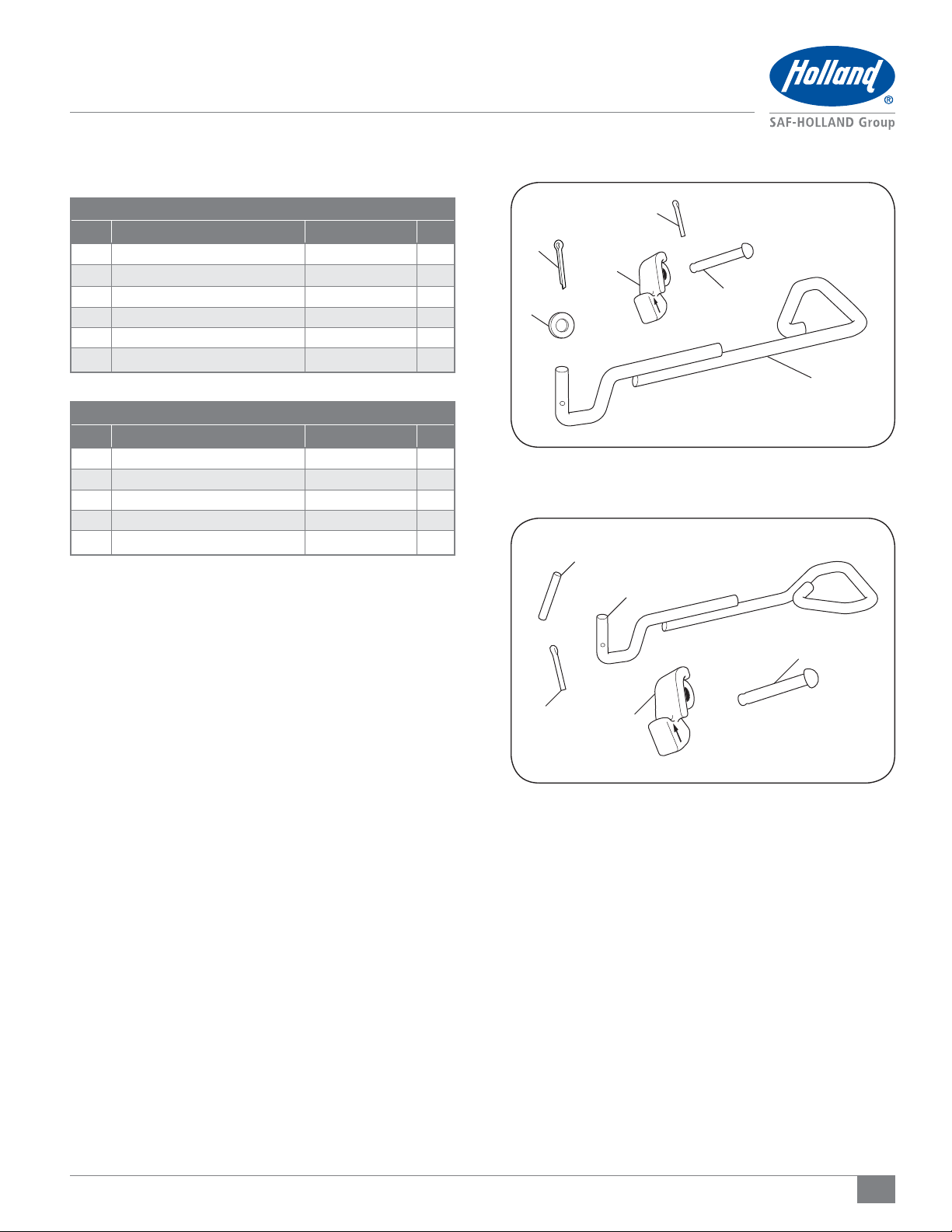
FWS1/FWS2 Manual and Air Release Handle
Introduction
This manual provides the information necessary to properly
replace the release handle on the XA-S1 and XA-S2 Series
Fifth Wheel Top Plates.
Read this manual before using or servicing this product and
keep it in a safe location for future reference. Updates to this
manual, which are published as necessary, are available on
the internet at www.safholland.us.
When replacement parts are required, SAF-HOLLAND®highly
recommends the use of only SAF-HOLLAND®Original Parts.
A list of technical support locations that supply SAF-HOLLAND®
Original Parts and an Aftermarket Parts Catalog are available
on the internet at www.safholland.us or contact Customer
Service at 888-396-6501.
Notes, Cautions, and Warnings
Before starting any work on the unit, read and understand all
the safety procedures presented in this manual. This manual
contains the terms “NOTE”, “IMPORTANT”, “CAUTION”, and
“WARNING” followed by important product information. These
terms are defined as follows:
NOTE: Includes additional information to enable accurate
and easy performance of procedures.
IMPORTANT: Includes additional information that
if not followed could lead to hindered
product performance.
Used without the safety alert symbol,
indicates a potentially hazardous
situation which, if not avoided, could
result in property damage.
Indicates a potentially hazardous
situation which, if not avoided, could
result in minor or moderate injury.
Indicates a potentially hazardous
situation which, if not avoided, could
result in death or serious injury.
General Servicing and Safety Instructions
Read and observe all Warning and Caution hazard alert
messages. The alerts provide information that can help prevent
serious personal injury, damage to components, or both.
Failure to follow the instructions and safety
precautions in this manual could result in
improper servicing or operation leading
to component failure which if not avoided
could result in death or serious injury.
All repair and maintenance should be performed by a
properly
trained technician using proper/special tools, and
safe procedures.
NOTE: In the United States, workshop safety requirements
are defined by federal and/or state Occupational
Safety and Health Act (OSHA). Equivalent laws may
exist in other countries. This manual is written based
on the assumption that OSHA or other applicable
employee safety regulations are followed by the
location where work is performed.
NOTE: Before repairing the HOLLAND®Fifth Wheel review
the model number on the identification tag. This
replacement procedure applies only to the XA-S1
and XA-S2 series fifth wheels.
IMPORTANT: These instructions apply to the proper
replacement of the FWS1/XA-S1 and
FWS2/XA-S2 release handle. There are
other important checks, inspections, and
procedures not listed that are necessary,
prudent, and/or required by law.
Failure to properly repair and install
the fifth wheel could adversely affect
performance resulting in tractor trailer
separation which, if not avoided, could
result in death or serious injury.

2XL-FW20017RM-en-US · 2014-06-02 · Amendments and Errors Reserved · © SAF-HOLLAND, Inc., SAF-HOLLAND, HOLLAND, SAF, and
logos are trademarks of SAF-HOLLAND S.A., SAF-HOLLAND GmbH, and SAF-HOLLAND, Inc.
Model Identification
1. Model Identification
This manual contains the installation procedures for SAF-HOLLAND®
replacement kits RK-10990 and RK-11112. Before replacement,
verify the correct replacement kit for the fifth wheel top plate
being repaired.
Fifth wheel serial tags are located on the left side of the
fifth wheel top plate above the fifth wheel bracket pin, or on
the pickup ramps as illustrated. The part number and serial
number are listed on the tag as indicated (Figure 1).
Figure 1
U.S. AND FOREIGN PATENTS APPLY
Model No. XXXXXXXXXXXX
Serial No. XXXXXXXXXXXX
FAILURE TO PROPERLY INSTALL, MAINTAIN & OPERATE
THIS PRODUCT COULD RESULT IN TRACTOR TRAILER
SEPARATION CAUSING SERIOUS INJURY OR DEATH.
MADE IN
XXXXXX

3
XL-FW20017RM-en-US · 2014-06-02 · Amendments and Errors Reserved · © SAF-HOLLAND, Inc., SAF-HOLLAND, HOLLAND, SAF, and
logos are trademarks of SAF-HOLLAND S.A., SAF-HOLLAND GmbH, and SAF-HOLLAND, Inc.
2. Replacement Kit Contents
Figure 3
Figure 2
Kit Contents
3
2
4
5
6
1
3
2
4
1
5
RK-11112 AIR RELEASE (TOUCHLOC) HANDLE (FIGURE 3)
ITEM DESCRIPTION PART NUMBER QTY.
1 Release Handle XA-11112 1
2 Cotter Pin, 1/8" 84261 1
3 Safety Indicator XD-11121 1
4 Roll Pin, 3/16" 9900181 1
5 Safety Indicator Pin XB-10996 1
RK-10990 REPLACEMENT KIT CONTENTS (FIGURE 2)
ITEM DESCRIPTION PART NUMBER QTY.
1 Release Handle XA-10990 1
2 Washer XB-T-49 1
3 Cotter Pin, 1/8" 84261 1
4 Safety Indicator XD-11121 1
5 Cotter Pin, 3/16" XB-11091 1
6 Safety Indicator Pin XB-10996 1

4XL-FW20017RM-en-US · 2014-06-02 · Amendments and Errors Reserved · © SAF-HOLLAND, Inc., SAF-HOLLAND, HOLLAND, SAF, and
logos are trademarks of SAF-HOLLAND S.A., SAF-HOLLAND GmbH, and SAF-HOLLAND, Inc.
Replacement Procedures
3. Replacement Procedures
Before performing the following replacement procedures,
make sure the fifth wheel is in the normal resting state with
ramps tilted down (Figure 4).
1. Lock the fifth wheel using a HOLLAND®Lock Tester, Part
Number 4000171 (Figure 4).
2. Working on the underside of the top plate, remove the cotter
pin from the lock indicator pin and detach the lock indicator
from the fifth wheel. Discard the cotter pin, lock indicator
pin and lock indicator (Figure 5).
3. FWS1/FWS2 Model:
Remove the cotter pin and washer from the end of the
release handle (Figure 6).
FWS1/FWS2 Air Release (Touchloc) Model:
Remove the roll pin from the end of the release handle
(Figure 6).
Figure 4
Figure 6
COTTER PIN
WASHER
ROLL PIN
FWS1/FWS2 FWS1/FWS2 AIR
RELEASE (TOUCHLOC)
Figure 5
HOLLAND LOCK TESTER
RAMPS TILTED DOWN
LOCK INDICATOR PINLOCK INDICATOR PIN
LOCK INDICATOR
COTTER PIN

5
XL-FW20017RM-en-US · 2014-06-02 · Amendments and Errors Reserved · © SAF-HOLLAND, Inc., SAF-HOLLAND, HOLLAND, SAF, and
logos are trademarks of SAF-HOLLAND S.A., SAF-HOLLAND GmbH, and SAF-HOLLAND, Inc.
Replacement Procedures
Figure 9
Figure 8
Figure 7
LEVER BAR
RELEASE HANDLE WINDOW
RELEASE HANDLELEVER BAR
RELEASE
HANDLE
WASHER
4. Separate the release handle from the lever bar (Figure 7).
5. Discard release handle, washer and cotter pin/roll pin.
6. Insert the new release handle through the release handle
window in the casting and into the lever bar (Figure 8).
7. FWS1/FWS2 Model:
Install the new washer and 3/16"cotter pin into the end
of the new release handle. Spread both legs of the cotter
pin at a 20° angle minimum (Figure 9).
FWS1/FWS2 Air Release (Touchloc) Model:
Install the new roll pin into the end of the new release
handle (Figure 9).
FWS1/FWS2 FWS1/FWS2 AIR
RELEASE (TOUCHLOC)
COTTER PIN
WASHER
SPREAD LEGS OF
COTTER PIN ROLL PIN

6XL-FW20017RM-en-US · 2014-06-02 · Amendments and Errors Reserved · © SAF-HOLLAND, Inc., SAF-HOLLAND, HOLLAND, SAF, and
logos are trademarks of SAF-HOLLAND S.A., SAF-HOLLAND GmbH, and SAF-HOLLAND, Inc.
Replacement Procedures
Figure 10
8. Position the lock indicator into the pocket on the release
handle window of the casting, ensuring that the lock
indicator is in the correct orientation (Figure 10).
9. Insert the lock indicator pin through the casting hole
and the lock indicator and attach with 1/8"cotter pin.
Spread both legs of the cotter pin at a 20° angle minimum
(Figure 11).
ALIGN HOLES
POCKET OF CASTING LOCK INDICATOR
Figure 11
LOCK INDICATOR LOCK INDICATOR PIN
LOCK INDICATOR PIN SPREAD LEGS OF COTTER PIN

7
XL-FW20017RM-en-US · 2014-06-02 · Amendments and Errors Reserved · © SAF-HOLLAND, Inc., SAF-HOLLAND, HOLLAND, SAF, and
logos are trademarks of SAF-HOLLAND S.A., SAF-HOLLAND GmbH, and SAF-HOLLAND, Inc.
Figure 12
Figure 13
Figure 14
Operation and Adjustment
4. Operation and Adjustment
Verify the proper operation of the fifth wheel by locking and
unlocking the fifth wheel using a HOLLAND®Lock Tester Part
Number 4000171. After each attempt, check that the fifth
wheel is properly locked.
IMPORTANT: Before using the fifth wheel, visually
inspect all components of fifth wheel
for proper operation while coupling and
uncoupling fifth wheel with lock tester.
IMPORTANT: DO NOT use any fifth wheel which does
not operate properly.
Failure to repair an improperly operating
fifth wheel could result in tractor trailer
separation which, if not avoided, could
result in death or serious injury.
1. If fifth wheel is locked, lift release handle up, pull
completely out, and up again to hook on casting. If air
release equipped, actuate fifth wheel control valve to
open lock (Figure 12).
2. Firmly position the lock tester into the fifth wheel top
plate to lock the fifth wheel (Figure 13).
3. Push the lock tester forward so that it is tight against the
fifth wheel’s front lock. Ensure the lock tester is pressed
flat against the surface of the fifth wheel. Scribe a line on
the surface of the fifth wheel face along the front edge
of lock tester (Figure 14).
LOCK INDICATOR
SCRIBE FIRST LINE
FIFTH WHEEL
FRONT LOCK
HOLLAND LOCK TESTER
RAMPS TILTED DOWN

8XL-FW20017RM-en-US · 2014-06-02 · Amendments and Errors Reserved · © SAF-HOLLAND, Inc., SAF-HOLLAND, HOLLAND, SAF, and
logos are trademarks of SAF-HOLLAND S.A., SAF-HOLLAND GmbH, and SAF-HOLLAND, Inc.
Figure 17
Figure 16
Figure 15
Operation and Adjustment
4. Pull the lock tester toward the fifth wheel ramps. Ensure
the lock tester is pressed flat against the surface of the
fifth wheel. Scribe a second line on the surface of the
fifth wheel face along the front edge of the lock tester
(Figure 15).
5. Rotate the lock tester out of the way and measure the
distance between the scribed lines. If distance between
lines exceeds 1/8" (3 mm), the lock MUST be adjusted
tighter (Figure 16).
6. To adjust lock:
With the lock tester still locked in the fifth wheel, lift
up on fifth wheel ramps and rotate fifth wheel to its
forward most position (toward the cab).
Remove clinch pin from the bottom of the lock
adjustment pin (Figure 17).
Lift the lock adjustment pin and rotate clockwise to
the next adjustment position shown on the face of fifth
wheel (Figure 18).
Push the lock adjustment pin into fifth wheel in the
new position.
Replace clinch pin.
7. Re-check for free play in the locks by repeating Steps 3-5.
If free play still exceeds 1/8" (3 mm), repeat Step 6 and
rotate lock adjustment pin one more notch.
NOTE: If free play greater than 1/8" (3 mm) remains
with the lock adjustment pin on the last (fourth)
position, then the fifth wheel should be rebuilt
using rebuild kit RK-FWS-A-L.
MEASURE DISTANCE
BETWEEN LINES
CLINCH PIN
SCRIBE SECOND LINE

9
XL-FW20017RM-en-US · 2014-06-02 · Amendments and Errors Reserved · © SAF-HOLLAND, Inc., SAF-HOLLAND, HOLLAND, SAF, and
logos are trademarks of SAF-HOLLAND S.A., SAF-HOLLAND GmbH, and SAF-HOLLAND, Inc.
Figure 19
Figure 18
Operation and Adjustment
8. Verify the proper adjustment and operation by locking
and unlocking fifth wheel several times with lock tester.
Verify that there is at least 1/16" (1.5 mm) of forward
and backward play in the lock by sliding a 1/16" drill bit
between the front edge of the kingpin on the lock tester
and the front lock (radius) of the fifth wheel (Figure 19).
IMPORTANT: A minimum of 1/16" (1.5 mm) free play is
critical to proper operation of the fifth wheel.
If there is NOT 1/16" (1.5 mm) minimum free play in
the lock, the fifth wheel lock adjustment pin MUST be
rotated counterclockwise to the next lower position.
Re-verify that 1/16" (1.5 mm) minimum play exists using
1/16" (1.5 mm) drill bit as described above. Check that
the fifth wheel is properly locked.
9. Rotate lock adjustment tool from side-to-side to ensure
that the lock is not over tightened. The lock should NOT
grip the kingpin and the lock tester should rotate freely.
DRILL BIT

10 XL-FW20017RM-en-US · 2014-06-02 · Amendments and Errors Reserved · © SAF-HOLLAND, Inc., SAF-HOLLAND, HOLLAND, SAF, and
logos are trademarks of SAF-HOLLAND S.A., SAF-HOLLAND GmbH, and SAF-HOLLAND, Inc.
Notes

11
XL-FW20017RM-en-US · 2014-06-02 · Amendments and Errors Reserved · © SAF-HOLLAND, Inc., SAF-HOLLAND, HOLLAND, SAF, and
logos are trademarks of SAF-HOLLAND S.A., SAF-HOLLAND GmbH, and SAF-HOLLAND, Inc.
Notes

SAF-HOLLAND USA · 888.396.6501 · Fax 800.356.3929
www.safholland.us
SAF-HOLLAND CANADA · 519.537.3494 · Fax 800.565.7753
WESTERN CANADA · 604.574.7491 · Fax 604.574.0244
www.safholland.ca
SAF-HOLLAND MEXICO · 52.1.55.5456.8641 · Fax 52.55.58162230
www.safholland.com.mx
From fifth wheel rebuild kits to suspension bushing repair kits,
SAF-HOLLAND Original Parts are the same quality components used in
the original component assembly.
SAF-HOLLAND Original Parts are tested and designed to provide
maximum performance and durability. Will-fits, look-alikes or, worse
yet, counterfeit parts will only limit the performance potential and
could possibly void SAF-HOLLAND’s warranty. Always be sure to spec
SAF-HOLLAND Original Parts when servicing your
SAF-HOLLAND product.
SAF-HOLLAND USA, INC.
1950 Industrial Blvd., Muskegon, MI 49443
www.safholland.com
XL-FW20017RM-en-US · 2014-06-02· Amendments and Errors Reserved · © SAF-HOLLAND, Inc., SAF-HOLLAND, HOLLAND, SAF, and logos are trademarks of SAF-HOLLAND S.A., SAF-HOLLAND GmbH, and SAF-HOLLAND, Inc.
This manual suits for next models
1
Table of contents
Other SAF-HOLLAND Industrial Equipment manuals
Popular Industrial Equipment manuals by other brands

KTR
KTR SYNTEX-NC Series Operating and assembly instruction

SKF
SKF TKBA 10 quick start guide

Dodge
Dodge Sleevoil STL instruction manual

Endress+Hauser
Endress+Hauser Silopilot FMM50 Brief operating instructions

Axi
Axi MTC HC-50 Installation, operating and maintenance manual

ABB
ABB HT523783 Operation manual