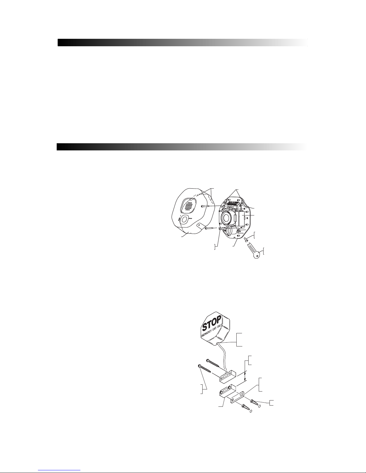
Safety Technology International STI-6400 Exit Stopper User manual

TI-6400 Exit topper®
IN TRUCTION MANUAL
“We Protect The Things That Protect You.”
afety Technology International, Inc.
Features:
• Helps prevent both unauthorized exits and entries
through emergency exit doors.
• Easy to install.
• Less expensive than heavy horizontal bar type units and
practical for all emergency doors.
• May be mounted on top, right, left or next to almost any
door.
• User can select onsite whether to use an alarm or
annunciator.
• Contact STI for custom applications .

2
TABLE OF CONTENT
WARNING
All units are recommended for indoor use, not for outdoor use. Unit must be tested periodically
to verify the life of battery. STI recommends you change the 9 Volt battery twice a year. Installer
may need to purchase a simple audio-meter, typically available at your local electronics store, to
measure the sound in areas where the alarm is expected to be heard during normal noise
environment. Results from this test may prove it beneficial to purchase additional exit stopper
units. When purchasing a remote unit (STI-6403) you will need to periodically test the connections
to make sure audibles function at a sound level to alert staff. Maximum of three STI-6403 may
be used in parallel.
All specifications and information shown are current as of publication and subject to change
without notice.
• Warnings and Cautions ................................................................................................Page 2
• Warranty Information ..................................................................................................Page 2
• Specifications ................................................................................................................Page 3
1. Dimensions ..............................................................................................................Page 3
2. Polycarbonate ..........................................................................................................Page 3
3. Electronics ................................................................................................................Page 3
4. Remote Horn ............................................................................................................Page 3
• Circuit Board Set-Up......................................................................................................Page 4
• Terminal Strip Layout....................................................................................................Page 4
• Switch Settings..............................................................................................................Page 4
• Alarm Feature Description............................................................................................Page 5
• Installation Instructions All Units / STI-6400 ..............................................................Page 5
• Mounting Options ........................................................................................................Page 6
• STI-6402 Double Door additional install notes ........................................................Page 7
• STI-6403 Remote Horn additional install notes ......................................................Page 7
• STI-6404 Double Door with Remote Horn additional install notes ........................Page 7
• STI-6405 Exit Stopper with Momentary Reset ........................................................Page 7
WARRANTY INFORMATION
Three year guarantee against breakage of polycarbonate in normal use (one year on electro
mechanical and electronic components).

3
PECIFICATION
Polycarbonate Enclosure:
Dimensions 5.375” W x 5.375” H x 2 “ D (137mm x 137mm x 51mm)
Flammability: UL94 V-2
Wall Thickness: 0.12 in (3.05mm)
Electronics: TI-6400 - All Units
9 VDC Alkaline or 9V-24VDC wired
Class II UL Listed transformer
Horn Volume at 1 ft. 95 dB low / 105 dB high
Relay Output Form C Dry Contacts 0-30 VDC or VAC, 1 Amp
Stand by Current 10uA
Alarm Current 130mA at 95 dB / 200mA at 105 dB
Electronics: TI-6403 and TI-6404 - Remote Horn Unit
Power Source 9 VDC Operating Power* only
Horn Volume at 1 ft. 95 dB low / 105 dB high
Stand by Current 0 A
Alarm Current 50mA at 95 dB/ 200 mA at 105 dB
*Power source for the STI-6403 Remote Horn uses a separate power source from the STI-6400
alarm. The Remote Horn contains an internal 9 volt battery. Horn operates when the Form C
contact at main unit is activated on alarm.
Power Source

4
JP5
JP2
JP4
JP3
JP7
SWITCH
ALARM
DURATION
ALARM VOLUME SWITCH
TRIP DELAY SWITCH
ARMING SWITCH
(FACTORY DEFAULT SETTINGS)
(ON)
(ON)
(OFF)
(OFF)
(OFF)
TERMINAL BLOCK
WITCH ETTING
CIRCUIT BOARD ET-UP
Volume - High (105 dB) at 1 ft. ON*
Volume - Low (95 dB) at 1 ft. OFF
Duration - 30 Second Alarm OFF* OFF*
Duration - 180 Second Alarm OFF ON
Duration - Continuous Alarm ON OFF
Duration - Annunciator Mode ON ON
Trip - Immediate OFF*
Trip - 15 Second Delay ON
Arming - Immediate ON*
Arming - 15 Second Delay OFF
FEATURE JP2 JP3 JP4 JP5 JP7
*Factory Settings
Note: Slide black lever to desired ON/OFF position as labeled on circuit board.
NC COM NO GD V+ RS1 RS2 KEYSW
TERMINAL BLOCK WIRING CONNECTIONS
FORM C
DRY
CONTACTS
REMOTE
POWER
INPUT
9-24 VDC
REED
SWITCH
TERMINALS
KEY SWITCH
TERMINALS
FIGURE 1

5
IN TALLATION IN TRUCTION
Note: STI recommends setting up unit and testing settings prior to mounting.
1. Make sure key switch is in the OFF
position.
2. Remove tamper screw on side of
unit and remove housing cover.
Save this tool for future servicing
and battery change (Figure 2).
3. Set switches, on circuit board, to
desired alarm settings (figure 1).
4. Test settings by connecting battery
or external power source. If using
external power source a Class II UL
Listed transformer is required. If
power is present at terminal block
(figure 1) 9V battery is in no-load
on standby power consumption.
19039 SCREW
6 x 1 1/4 in.
(2) PROVIDED
19018 ANCHOR
(2) PROVIDED
BOTTOM SURFACE AS SHOWN
WIRES THROUGH NOTCH ON
AND ROUTE REED SWITCH
REMOVE FRONT COVER
VIEW SHOWING MAGNET INSTALLATION
MAGNET
MAXIMUM GAP 3/4 in. (19mm)
3/8 in. (9.5mm) ON METAL DOOR
AND FRAME
SPACERS (USE AS NECESSARY)
NOTE: 2 SPACERS UNDER BOTH
MAGNET AND REED SWITCH
MUST BE USED ON STEEL DOORS
FIGURE 2
FIGURE 3
ALARM FEATURE DE CRIPTION
• Volume witch JP2 - Sets alarm volume to high 105 dB or low 95 dB.
• Duration witch JP3 and JP4 - Amount of time alarm sounds after trip. Arming resets at end
of duration if door is closed. Alarm will not reset if in continuous mode; alarm sounds until
battery is drained. Annunciator Mode is a series of 10 short beeps or until door is closed.
• Trip Delay witch JP5 - If you wish to ENTER an alarmed door without sounding the horn
immediately, the trip delay will allow 15 seconds for you to enter and de-activate the alarm
with the key switch before the alarm will sound.
• Arming witch JP7 - This mode is useful when an AUTHORIZED EXIT is required through
alarmed door. In “ON” position immediate arming will set the alarm ready to function as soon
as door is opened. In “OFF” position delay arming will allow 15 seconds for you to exit through
the door without sending alarm signal.
5. Mount main unit on or next to door using
hardware provided. Reed switch mounting
locations can be moved to one of the four
positions shown in figure 2. If mounted
next to door, route reed switch wire
through knockout in bottom of housing as
shown in figure 3.
6.Mount magnet on door frame (or door if
unit is mounted next to door) using screws
provided. When mounting on metal doors
or door frames, use plastic spacers
provided. Reed switch and magnet must
be within 3/4” when door is closed (3/8”
on metal door and frame). Please refer to
figures 4, 5 and 6 on page 6 for other
mounting options.
7. If installing STI-6402, STI-6403, or STI-6404
continue to page 7 for more instructions
(Figures 7 and 8). STI-6402 mounting
option is shown on page 6.
8. Replace cover by sliding flanges on inside
of cover into slots on base. Then rotate the
cover over unit and snap close. Replace
tamper screw.
FLANGES SLOTS
TERMINAL STRIP
9 VOLT BATTERY
19011 TAMPERPROOF SCREW
(1) PROVIDED
19016 TAMPER WRENCH
(1) PROVIDED
BASE
COVER
19014 MOUNTING SCREW
(4) PROVIDED
EMERGENCY EXIT ONLY
STOP
STOP
ALARMSOUNDSWHENDOORISOPENED
ON
OFF

6
MOUNTING OPTION
DOOR
DOOR STOP
JAM
MAGNET
6400 UNIT
MAGNET MUST BE
INSTALLED OPPOSITE
RAISED RIB ON OUTER COVER.
SPACERS - USE
AS NECESSARY
19018 ANCHOR
(2) PROVIDED
TYPICAL FLUSH MOUNT DOOR JAM
INSTALLATION
DOOR
SWING
NOTE: 2 SPACERS MUST BE
USED ON STEEL DOORS
19039 SCREW
6 x 1 1/4 in.
(2) PROVIDED
MAGNET
6400 UNIT
DOOR STOP
SWING
DOOR
TYPICAL RECESSED MOUNT DOOR JAM
INSTALLATION
3/4 in. [19 mm]
MAXIMUM GAP
3/8 in. [9.5mm] ON
METAL DOOR AND FRAME
MAGNET ASSEMBLY
(SEE ABOVE FOR INSTALLATION)
FIGURE 5
FIGURE 4
*Note: W en mounting reed switc on door and t e main unit on wall, wire service loop must be used.
FIGURE 6
TYPICAL DOUBLE DOOR INSTALLATION
STI-6402

7
TI-6402 DOUBLE DOOR IN TALL NOTE
TI-6403 REMOTE HORN IN TALL NOTE
STI-6403 REMOTE HORN UNIT INSTALLATION
ROUTE WIRES
THROUGH NOTCH KEY SWITCH
06402 REED SWITCH
(RS1)
06402 REED SWITCH
(RS2)
OPTIONAL:
TO REMOTE
HORN
STI-6403
VIEW SHOWING INSTALLATION OF
ADDITIONAL REED SWITCH 06402
TO KEY
SWITCH
TERMINAL BLOCK
A
FIGURE 7
FIGURE 8
1. Remove cover.
2. Connect two conductor wire (14-24 AWG)
from main unit terminal block pins COM and
NO to remote horn unit terminal block.
(wire not provided). Units can be set up to
300 ft. apart. Not polarity sensitive (refer to
Fig. 1 and Fig. 7 for details).
3. Connect internal battery.
4. Mount similar to main unit with #8 x 1 in.
screws and anchors if necessary.
5. Replace cover and screws.
6. Turn key switch to ON position.
*Note: The ON/OFF key position is opposite
from 6400 main unit. Remote horn sounds
when main unit alarm is activated.
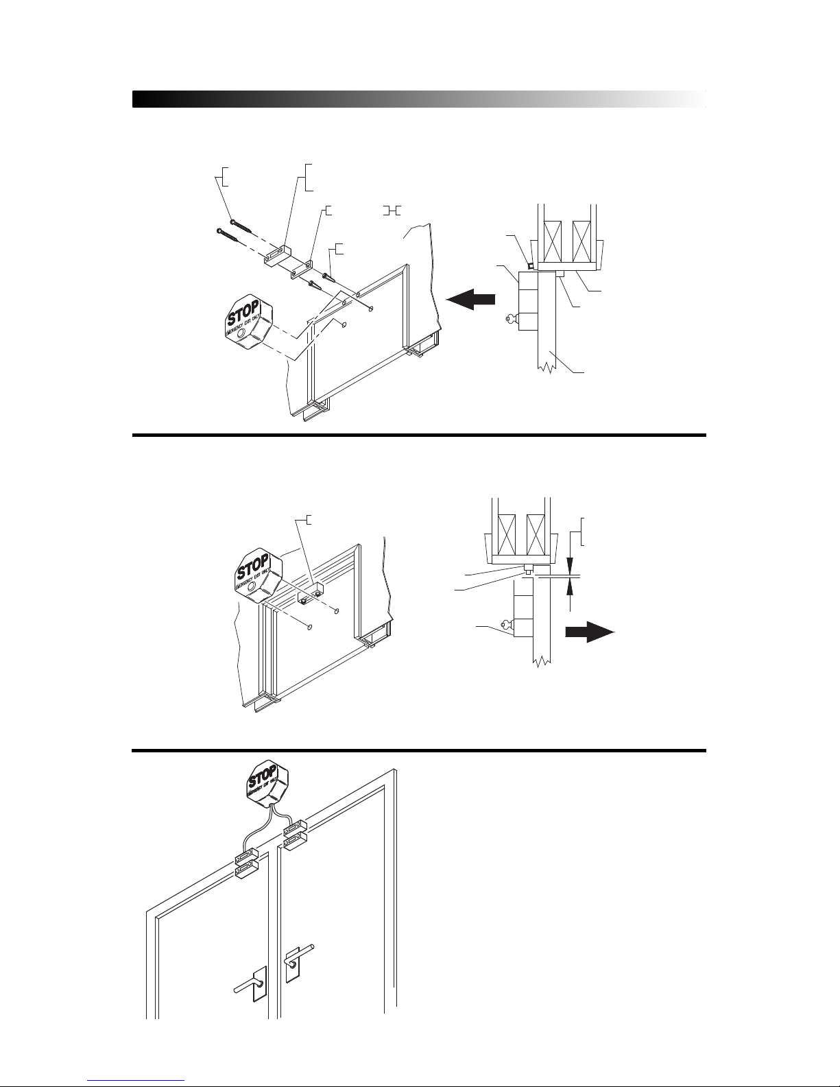
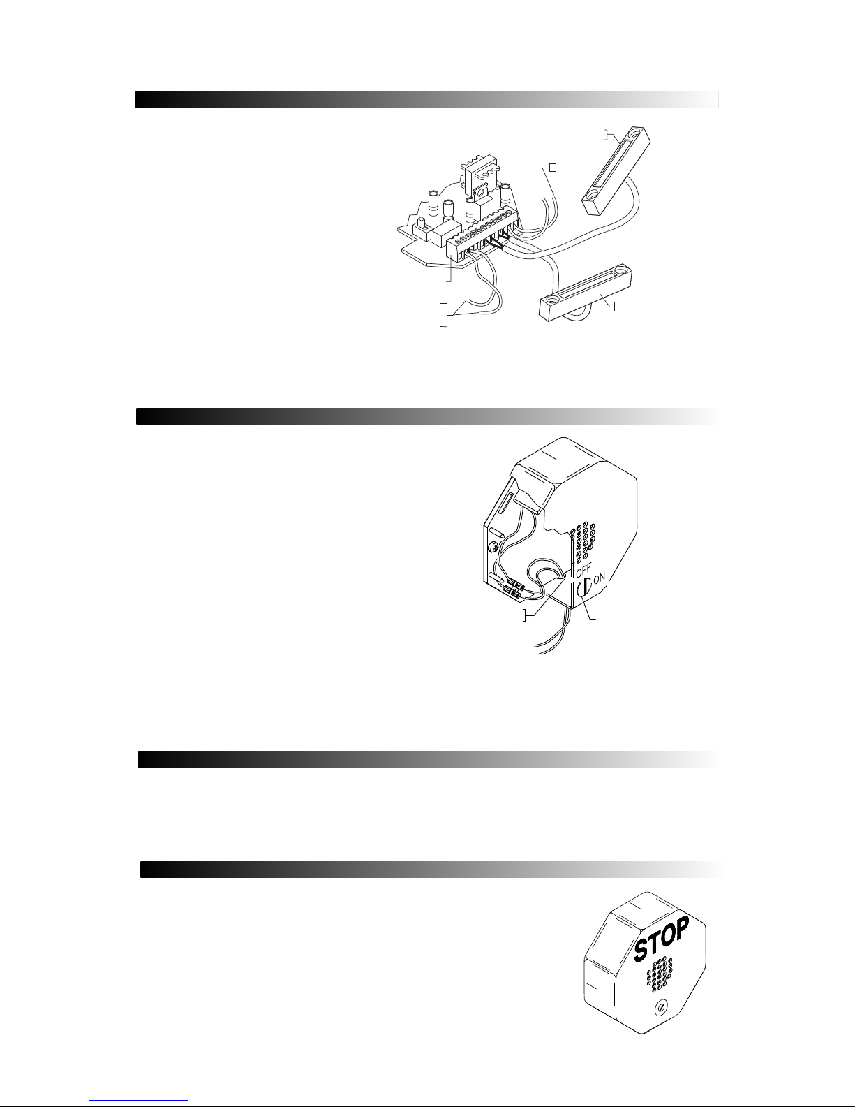
1. Determine length needed for reed
switch wires. STI provides 6 ft. which
can be cut to desired length.
2. Connect first reed switch in RS1 and
second in RS2 (Figure 7). (Refer to
Figure 1 for additional details on
page 4.)
3. If not using extra reed switch, add
jumper across two terminals of RS2
on terminal block.
*Note: Alarm will sound when either
door is opened.
TI-6404 DOUBLE DOOR WITH REMOTE HORN IN TALL NOTE
The STI-6404 is a combination unit for double doors with a remote horn. Reference the
installation instructions for the main unit, the STI-6402 and the STI-6403 for complete
installation.
TI-6405 EXIT TOPPER WITH MOMENTARY RE ET
The STI-6405 uses a momentary switch. After initial installation, unit
is always on and you do not have to remember to turn it on when
you leave a protected area. This model also eliminates having to
remember to re-arm it because it is never off.
When the alarm is triggered, to silence the alarm, insert the key and
turn completely to the "RESET" position and hold for 2 seconds, then
release. The switch will spring back to its original position and push
the key out. To turn the unit off, supply power must be removed.
RESET
Table of contents
Other Safety Technology International Security Sensor manuals

Safety Technology International
Safety Technology International 34701 User manual

Safety Technology International
Safety Technology International Exit Stopper STI-6400 Series Instructions for use

Safety Technology International
Safety Technology International STI-7535MED Original operating instructions

Safety Technology International
Safety Technology International STI-34701 User manual

Safety Technology International
Safety Technology International STI-34701 User manual

Safety Technology International
Safety Technology International STI-34752 User manual