Safety Track UCIT User manual

UCIT BASIC/LIVE 2 CHANNEL
Vehicle Video Recorder
User Manual/Installation Guide
!
2015 JAN V 1.1

Table of Contents
A. Features.................................................................................... 1 !
B. Specifications .............................................................................2 !
C. Structure of Product..................................................................5 !
D. Dimensions ................................................................................. 5 !
E. Installation Guide ...................................................................... 6 !
F. Functions of Remote Controller ................................................7 !
G. Start / Stop Recording.............................................................10 !
H. Software Player Instruction ..................................................... 11 !
I. Formatting Memory Card ........................................................ 19 !
J. Restoring Memory Card..........................................................21 !
!

A. Features
1. Suitable for all personal vehicles i.e taxi, bus, trucks etc.
2. Small size, easy installation and dismount, it does not affect !
the driver's line of sight.
3. Insert the SD card and power on to start recording without !
additional operating.
4. Simultaneously recording interior and exterior condition.
5. Having full time, date recording and display on the screen !
directly.
6. Recording driving condition, sound, G-Sensor and GPS !
data.
7. Front view angle approx. 120 degrees. Back view angle !
approx. 170 degrees.
8. Recording track of driving routes which can be shown on !
Google Map when we play the video.
9. Micro SD memory card Class 10 or above recommended.
10. G-sensor sensitivity can be adjusted according to road !
situations. When a strong shock is detected, system will start
emergency recording and keep the files without being overwritten.
11. Professional file formats, without built-in lithium battery, no need to
afraid of heat and bursting concerns, it is the real black box.
12. 3G/4G Live Streaming Capability!

B. Specifications
Item / Specification
Chipset
H.264 image compression chip
Sensor Device:
Forward facing lens: 720p CMOS Sensor
Backward facing lens: VGA CMOS Sensor.
View Angle
Outside vehicle approx : 120 degrees
Inside vehicle approx : 170 degrees
Voltage
Please use 5V±5%, 1A Cigarette lighter adapter. The machine needs 4.7v to start.
Operating Temp
-15°C~+55°C (Inside Vehicle).
Storage Device
Micro SD Card (16GB/32GB/64GB) Class 10 or above SD Card Recommended
Recording Frame
!
Forward facing lens: 1280x720; Highest resolution: 30fps/25fps (NTSC/PAL)
Backward facing lens: 640x480; Highest resolution: 15fps/15fps (NTSC/PAL)
Auto record when system is powered up; backward facing lens can be disabled by
settings in software menu.
Recording Content
Date, time, image, sound, G-sensor data, GPS data.
Recording Format

Specific format for software player.
Microphone
Build-in high sensitivity of single microphone for automatic voice adjustment.
Time Setup
Auto-calibrating by GPS signals. If GPS is not available, the built-in clock will be used.
G-Sensor
Internal 3D G-Sensor.
Out Device
. (a) TV-Out (1 Vp-p composite video output, 75 ohms), Video Output format:
NTSC / PAL alternative. !
. (b) Force Record Button: For emergency recording. Gleams in night time. !
. (c) Red light: Recording indicator. In emergency recording, it flashes more
frequently. !
. (d) Green light !
Flashing: Searching GPS signals. Light on : GPS positioning ready !
. (e) External hole to connect GPS Mouse !
Note: When IR turns on, the LED light will be dimmer.
Description
. (a) The GPS positioning speed will be influenced by solar film of the front
windshield, weather or other environment factors. !
. (b) Starting and closing time of infrared will be subject to light intensity, the
installation location, front windshield and other factors.!

. (c) Day and night mode has a delay for about 30 seconds. Night mode will be
priority when powered on. !
. (d) Memory card formatted by using the playback software. This may be done for
you already.!
Important Notice
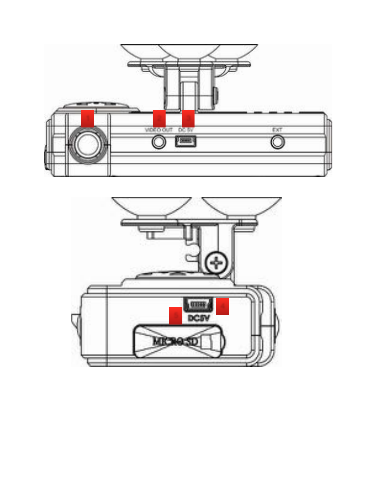
. (a) The current consumption of the system over standard USB hole (output
500mA). When connect with PC power supply, it's better to buy another power
cable with two holes for portable hard drive. !
. (b) System must be installed in the area that wipe can be reached to ensure the
clarity of recording video. !
. (c) Please do not plug the power in both micro-USB sockets. The system might
get damaged.
. (d) If you do not use the player to format memory card, the system will be forced
to format the entire memory card and then start recording. !
. (e) It's better not crossing the top of the machine and the left side of GPS. We
suggest to put the cables via the right side of the VVR and then connect to the
ceiling to get better GPS signal. !
. (f) Initial screen and Live View screen may change due to software update or
revision without notice. !
. (g) The machine itself has a distinction between NTSC or PAL. Video output to
the monitor with corresponding screen system. !
. (h) Interior lens adopt ultra-wide-angle lens. There will be slight cover corner
phenomenon at the corner edge. !
. (i) Memory card has the number of reading and life issues, please check and
use the computer to play video regularly in order to make sure the memory card
can read and write properly.

Accessories
!
Standard:
Camera System
Hardwire Kit (Battery Backup/Charge Guard)
Suction cup bracket with cups, Bracket holder and Adhesive mount option
Optional: (a) Micro SD card (16GB/32GB/64GB/128GB)
Add On:
3G/4G Dongle for Live Streaming

Structure of Product
1. Force Recording Button Recording Indicator
2. Recording Indicator
3. GPS Indicator
4. IVR LEDS
5. Light Sensor
6. Backward Facing Lens
Structure of Product (Continued on next page)
1
6
5
4
3
2

1. Forward Facing Lens 4. DC5V(1) Power cable Port
2. Video Out 5. Micro SD
3. DC5V(2) 3G/4G Dongle Port
※Please do not plug the power in both micro-USB terminals. The system can be damaged!
1
4
2
3
5

D. Dimensions
UNIT:mm

E. Installation Guide
Installation Guide
continued on next page…
Make the bracket face upward.
Assemble the suction cups.
Set up the device in the proper
position.
Adjust the viewing angle.

Installation Guide
continued on next page…
Plug 3G/4G Dongle into DC5V (1)
Socket.
Plug the Power Cable into DC5V (2)
Socket.
Wire Schematic:
Yellow: Power
Blue: Ignition Signal
Black: Ground
Step 1: Hardwire to vehicle according
to schematic above. (extend wire if
needed)
Step 2: Use electrical tape to conceal
exposed wires once connected. Test
Ignition to insure proper connection.
Step 3: Conceal Charge Guard/Battery
Backup box and wires.
Step 4: Plug in Longer Black Cable to
Camera.
When the power is successfully
connected, the IVR LED will light on for
10 seconds.

Force Record Button light is also on
when power is successfully connected.
Green light is GPS. This light will flash
when GPS is positioning, Light will be
on and solid when GPS is ready.
Red light is recording. Flashing
signifies recording, fast flashing
occurs in emergency mode or force
record.
Force Record Button: When pressed,
the red light (recording) will flash
rapidly. In night time situations the
Force record light will come on as an
indicator.
Installation Complete!
Other manuals for UCIT
3
This manual suits for next models
1
Table of contents
Other Safety Track Dashcam manuals

Safety Track
Safety Track UCIT User manual

Safety Track
Safety Track UCIT BASIC/LIVE 4 User manual

Safety Track
Safety Track UCIT BASIC/LIVE 4 User manual

Safety Track
Safety Track UCIT LIVE 4 Camera DVR User manual

Safety Track
Safety Track UCIT 2 User manual

Safety Track
Safety Track UCIT BASIC 2 User manual