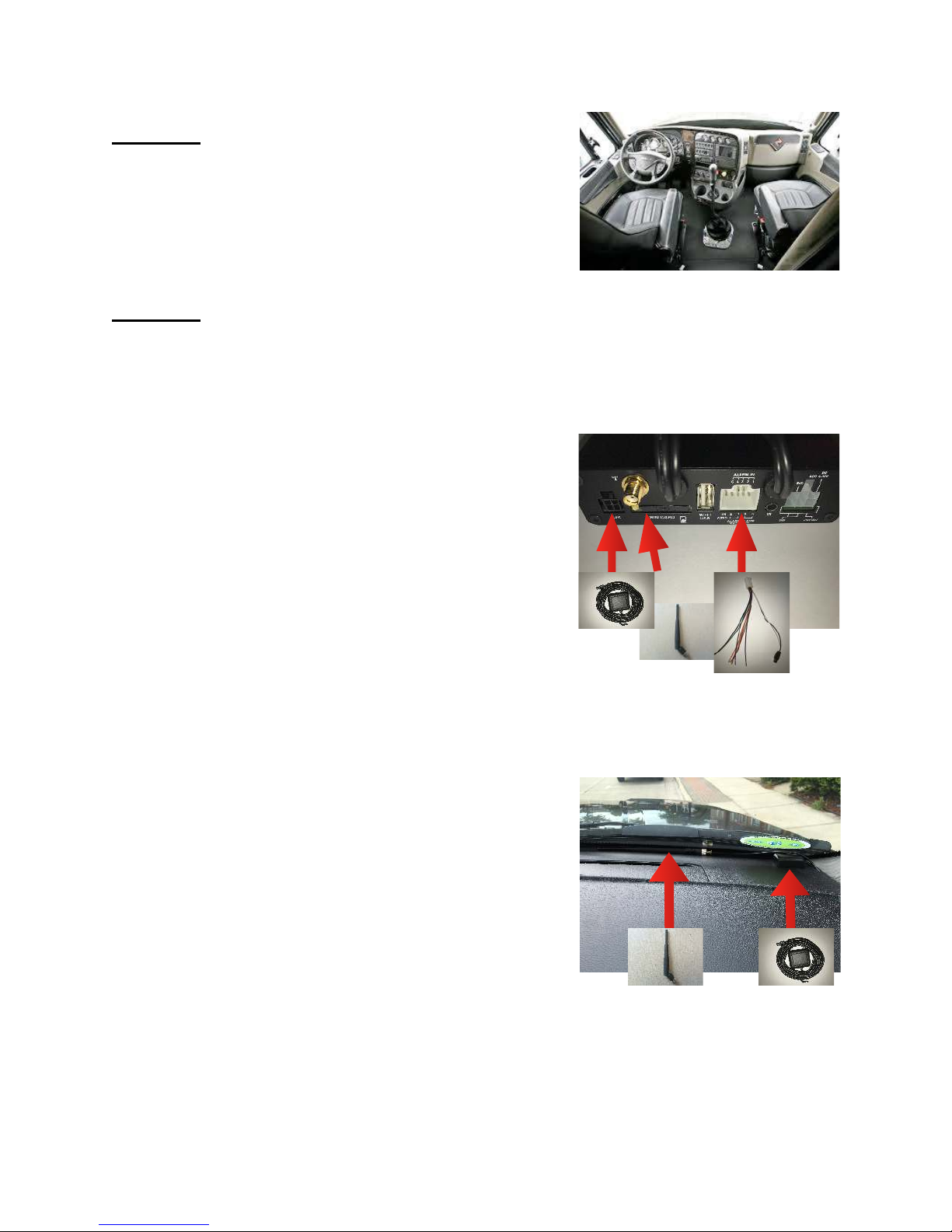
Safety Track UCIT LIVE HD User manual

!
UCIT LIVE HD 4 Camera DVR
Installation Manual
04/17 Version 1.0

!
This is a step by step guide that will walk you through installing the UCIT
LIVE HD 4 Channel Camera System. Basic wiring experience and
knowledge is required at the minimum. Please follow each step, otherwise
your system may not work properly. If you have any questions regarding
the installation of this system contact Support at 888-286-9829 Press #6 or
Support@SafetyTrack.net. We are always available for questions when
needed. Please take your time, take caution and Enjoy!
Tools Required:
•Power Drill
•Volt Meter
•Wire Crimpers
•Wire Strippers
•Electrical Tape
•Zip Ties
•Wire Connectors (Installer’s
Choice ex.T-tap, ring connector,
or simply poke and wrap)
•Extra wire (Shouldn’t need but
just in case)
•Screwdrivers (flat head and
philips)
•Self Tapping Screws
•3M Double Sided Trim Tape*
•Auto trim removal tool*
•Flashlight*
What’s In The Box:
•DVR (SD Card Pre-Installed)
•Power Harness
•Accessory Harness
•Camera(s) (individually boxed
with mounting hardware)
•Camera Cable(s)
•GPS Antenna
•Individually Powered Microphone
and Extension Wire
•Whip Antenna
•Whip Antenna Extension

Notes and Precautions
Please make sure power connections are clear to you before you make the
connection.
Please Follow this Guide STEP BY STEP do not skip around.
It is normally required to have a professional installer install these units.
Keep DVR System away from liquids, heavy dust and dirt, fire and extreme
temperatures.
If possible keep the equipment in a well ventilated area.
Review packing list or “whats in the box” to make sure you have everything.
NOTE: Any modifications to the device or software outside of company standards
without company approval are not a responsibility of Safety Track and will void
the warranty.
Getting Started:
Familiarize yourself with the contents of the box. Plan where the DVR will be
mounted and how you will run the cameras before you connect to a power source.
Also keep in mind any special instruction from Sales Rep or Customer on
mounting location of the DVR, cameras and antennas. Remember to conceal all
wires and cabling the best as possible unless otherwise directed.

Step 1:
Find a suitable location to mount the DVR
in such a way that is accessible to the fleet
manager. (To pull SD card and for troubleshooting)
The DVR can also be hidden if requested.
Step 2:
After unboxing the equipment, and getting
acquainted with what’s included, start by plugging
in accessories.
A. Plug in and run the GPS Antenna.
(square shaped) Anywhere that has a direct
sightline to the sky for best reception.
B. *T-Mobile and WIFI Models Only.
Attach the whip communication antenna to the
gold threaded nob protruding from the DVR. In
most cases it is best to use the antenna extension
provided so you can mount it away from the DVR
to ensure optimum performance.
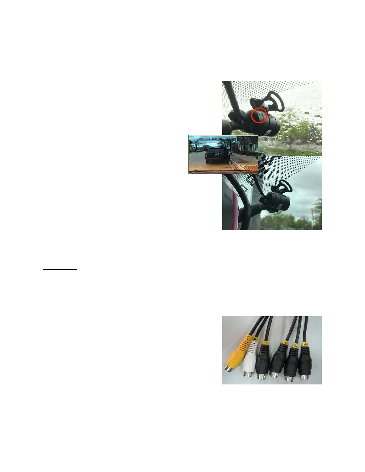
To the right is an example of a mounting location.
Whip is adhered to a window or windshield of
the vehicle. Another commonly placed location for
Whip is in the A pillar. This way the Whip is out
of sight. The same goes for the GPS Antenna.
When it comes to the GPS specifically, make sure
that the GPS receiver is sticker side down.
B
A
C
A
B

C. Plug in the Accessory Harness for the
microphone (If Applicable).
Follow the steps below to ensure proper connection
of the microphone:
B1. -
DVR
Find the Accessory
Harness RCA (Female)
White Wire Only
C
Find the Microphone
Extension
Yellow RCA (Male) and
Red plug (Female)
1
Plug the Yellow RCA
(Male) from Microphone
Extension into the RCA
(Female) on the
Accessory Harness.
3
Find the Power
Harness Black Plug
(Male)
Plug the Black Plug
(Male) from the Power
Harness into the Red
Plug (Female) on the
Microphone Extension
4
Find the Microphone
White RCA (Female)
and Red Plug (Female)
6
5
2

Place the Microphone so that it is visible and in an
optimum position to get the best clarity. Pictured
right is a recommended placement example.
Driver side A-Pillar, this way it is near the driver.
Step 3:
Mount the cameras as directed or as needed. Each camera is individually packaged
with mounting hardware supplied. Every camera type is different when it
comes to mounting or adjustment. Following are a
few examples of camera mounts and positions.
Camera Model: ST-1252
Ensure cameras are aimed properly by
adjusting screws or post wheel. The
Screws adjust the camera tilt and the
wheel adjusts camera position. In the
example to the right the camera is
mounted with the supplied 3M Trim tape.
This Camera is placed in the upper corner
of the windshield on the passenger side for
a driver view. This is a very versatile camera
because it can be mounted to achieve specific
angles as well as be mounted in or on the exterior.
7
Plug Yellow RCA (Male)
from Microphone
Extension into White
RCA (Female) on
Microphone
8
Plug Red Plug (Male)
from Microphone
Extension into Red
Plug (Female) on
Microphone

Camera Model: ST-1231
Ensure cameras are properly aimed by adjusting
the 4 screws on both sides of the camera shown
at the right. This camera example, as you can see,
has also been mounted with 3M trim tape.
The bracket attached to this camera is
steel and will allow for screw mounting a
a bit easier.
This camera type is typically placed on
the exterior of a vehicle. Much like the
ST-1252, its weatherproof. In the example to the
right you see it being mounted to achieve an
exterior rear view.
This camera can also be used as a side mount.
Simply by using the hardware supplied in the box.
To the right you will see the hardware required to
adjust the bracket to either side of the camera.
Place the raised plastic mount on the top and the
bottom of the camera, use the small screws to
mount the plastic piece.
Once you have the raised plastic piece mounted
you can fit the bracket and secure with an allen
screw. Finished product shown to the right.
This view is beneficial to capture common side
swipe incidents or to capture blind spots.

When it comes to the interior (Non-IVR) Camera
there is a small grove etched into the back. (Shown
Right) This indicates when the camera is up right
and in the proper position. Etching should line up
with the T in the bracket.
You may need to loosen the allen/hex screw with
the supplied key. (in the box) This will
allow you to adjust the mounting stand
angle. This will also loosen the bracket
holding the camera so you can rotate it if
needed. Be sure to line up the groove
etched into the back of the camera to
ensure a straight and proper position.
Example to the right shows a popular mounting
position on a vehicle’s windshield (interior).
This would require rotating the camera inside the
bracket by loosening the bracket screw.
Step 4:
Run camera cables with supplied 5 meter
extension cables. Ensure proper connection, use
electrical tape if needed.
DVR Pigtails:
V - Video Output
A - Audio Output N/A
1. Camera 1 Video Input
2. Camera 2 Video Input
3. Camera 3 Video Input
4. Camera 4 Video Input
*If monitor is used for a backup camera view, make sure the camera you want to
use as a backup camera is plugged into Camera 1 Video input.

This step describes how to plug in the cameras and
mounting. Which ever you prefer to do first.
In most cases it is easier to mount the cameras as
long as you know you will have enough cable.
NOTE: Be sure to line up the arrows on both ends
of this connection otherwise the cameras won’t
connect and you could damage the pins.
To the right you will see Channel 1 from the DVR
(Male) plugs into the corresponding camera
extension (Female).
The other end of the extension (Male) Plugs into
the pigtail coming from each camera you will need
to line up this connection as well.
NOTE: Line the groves up for a fit. No force.
Lastly, and a very important step is to create a
watertight seal, using the supplied seal, pictured to the
right. Find the How To Video on our website.
Step 6:
Run the power cable to a power source.
Typically the ignition harness under the
driver side steering wheel. Test and make sure
you have a constant power source and a proper
ignition source.
1. Ground (Black)
2. Ignition (Blue)
3. Power (Yellow)
4. N/A
5. Microphone Ground
6. Microphone Power
Make the connection then attach 6 pin to DVR.

Step 7:
Ensure proper connection by checking the lights on the DVR. If you see lights then
you have power. It may take a few seconds for lights to come on after you connect.
Red = Recording. Blue = GPS. Orange = Network.
-Red will consistently blink every second or so to indicate recording and writing to
the memory card.
-Blue will be solid when GPS Lock is achieved.
-Orange will be solid when connected to the network.
Clean up! INSTALLATION COMPLETE!
Table of contents
Other Safety Track DVR manuals
Popular DVR manuals by other brands

Digi-IT
Digi-IT DIS-4000 user manual

Siemens
Siemens DMS8000 Installation Operation, Manual, Configuration

KGuard Security
KGuard Security Easy Link EL421 user manual

LTS
LTS LTD8424T-FA quick start guide

AGI Security
AGI Security VC-SYS-HT1603 quick start guide

Crest Electronics
Crest Electronics CDVS-5400 SERIES user manual