AA1081 INVERTER / BUFFER SYSTEMS CARD
Description
The AA1081 INVERTER / BUFFER SYSTEMS CARD is a stand alone module
that is designed to provide analog signal conditioning in a variety of motor control
applications. It provides signal buffering, signal Inverting and the ability to sum
(2) input signals. It has an offset as well as a gain adjustment.
Specifications
Power Requirements - (+ / -) 12 VDC @ 30 mA (max.)
Maximum Output Voltage - (+ / -) 10 VDC
Maximum Input Voltage - (+ / -) 10 VDC
Input Resistance - 10 K (inverting and non-inverting)
Minimum Load Resistance - 1 K
Offset Adjustment Range - (+ / -) 0 –2.5 V @ G = 1 (factory set for 0 V)
Gain Adjustment Range - G = 0.5 - 10 (factory set for 1)
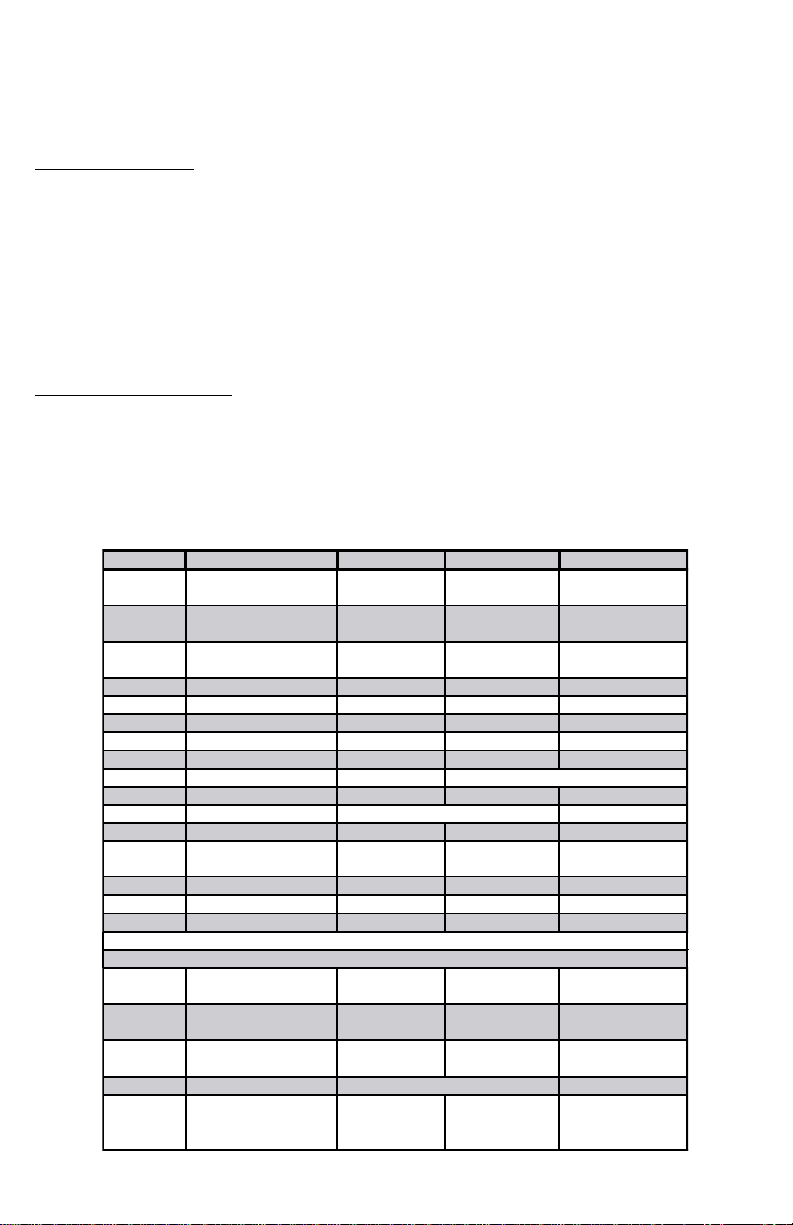
Installation
Before attempting any installation make sure that all power is turned off to
the equipment being worked on. The AA1081 card is a stand alone module
and can be mounted in a variety of ways. It should be mounted in a protective
enclosure which is well ventilated. Four mounting holes are provided as shown in
Fig. 1B for use with stand-offs. Referring to Fig. 1A,make all external connec-
tions using shielded twisted wire. All wiring should be in accordance with
good standard practices and any codes that may apply.
PAGE 12
Appendix 1B
PAGE 5
4 - Adjust RV5 (Integral Time) to approximately 10% CW.This will set an integra-
tion time of 0.5 SEC. Next, adjust RV4,(Integral Output), to approximately
10% CCW which will a provide a 1V maximum integration error to be summed
with the proportional error at terminals 5 and 11. On the AA1069 board, re-
move the jumper J1, if installed.This will allow the output from the integrator
to be bi-polar (+/-).
NOTE: In some applications, it is desirable to have a + or – output.This
is set by the jumper position on P1.
5 - Connect the voltmeter to terminal 5, (Integral Output), and momentarily re-
move the jumper from terminal 10 (Enable).This will reset the integrator and
terminal 5 should read 0 V. Reconnect the jumper and note that the voltage
on terminal 5 should ramp up to approximately +1 V in 0.5 SEC.
6 - Adjust RV3 (Derivative Control) to fully CCW (0 SEC).There is no pre-set for
this control and it’s setting is application dependent.
7 - The Minimum Adjustment potentiometer RV2 provides a minimum excitation
voltage to the Dancer potentiometer when there is no Line Speed Reference,
such as on start-up. This setting is also application dependent and is nor-
mally set so that a neutral Dancer position is maintained. It is initially set
fully CCW (0 V).
In summary, using the initial settings, a full range change in the mechanical
Dancer position will provide a (+/-) 10% proportional change in the set Line
Speed.The Integral output, which is summed with the proportional change, will
be limited to a maximum of 1 V, with an integration time of 0.5 SEC. The deriva-
tive time is set to 0 SEC by RV3, and the minimum Dancer excitation voltage is
set to fully CCW (0 V) by RV2. The neutral Dancer operating position can be set
by the Dancer position potentiometer. However, it is recommended that the
mechanical Dancer neutral position be set in the middle of the mechanical range
so that full range control may be realized.