87
LATERAL TRANSFER
WARNING: Always use at least two caregivers while performing
the Lateral Transfer. • Exterior bed rails on both surfaces should be
raised prior to transfer to prevent the patient from falling. If there are
no bed rails used, the caregivers are responsible for making sure the
patient does not reach outside the boundaries of either support surface.
• To avoid potential skin injury, ensure the patient’s head and feet are
supported to prevent them from dragging across the support surface.
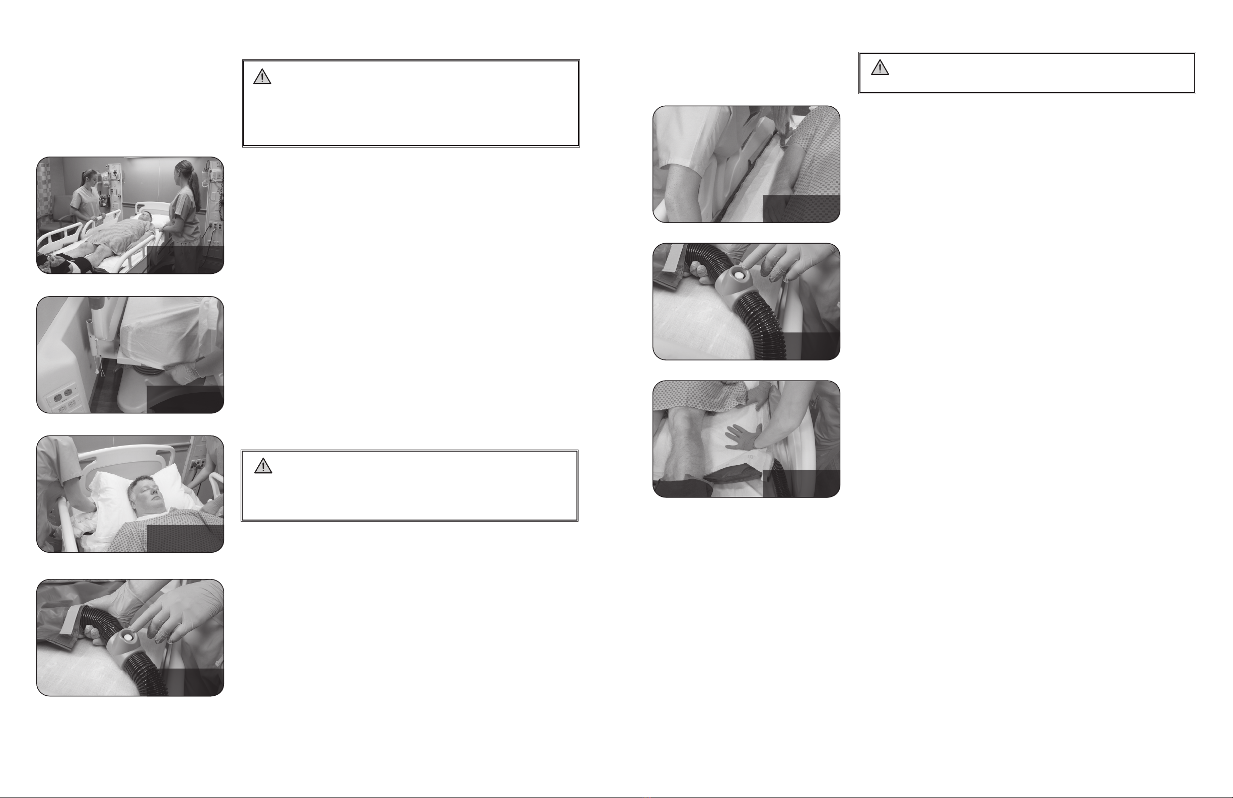
1. Lock the bed brakes and raise the bed rails. Place the sending support
surface in a horizontal position and at the caregiver’s waist level.
STEP 8
STEP 10
STEP 12
STEP13
Sending and Receiving
surfaces pushed together
Clinician on opposite sides
Glide Sheet deated
STEP 3
STEP10
Show mid transfer shot
STEP 11
Show mid transfer shot
STEP 17
5. Ensure the patient’s head and feet are supported.
6. Caregiver A lower the bed rail where the Wedges will be inserted.
7. Caregiver B use the Black Positioning Handles to secure the Glide Sheet.
8. Caregiver A grasp the Black Positioning Handle on the Glide Sheet
and insert the Anchor Wedge, tail rst and with the black fabric
facing up, so that the Anchor is underneath the patient’s thighs.
9. Caregiver B pull the tail through until it is taut.
10. Caregiver A grasp the Black Positioning Handle on the Glide Sheet
and insert the Upper Wedge at least one hand width away from the
Anchor Wedge.
11. The caregiver on the side of the bed where the Booster Pump is
connected pushes the Power Button to turn the Booster Pump off.
12. Perform a microturn while the Glide Sheet is deating, if needed.
With both caregivers on the same side of the bed, grasp the Black
Positioning Handles, palms down.
Gently pull, DO NOT lift, until the patient is positioned at the
desired angle.
13. After the Glide Sheet is fully deated, check to ensure the patient’s
sacrum is ofoaded.
14. Raise the bed rails.
WARNING: DO NOT use the Glide Sheet to lift patients.
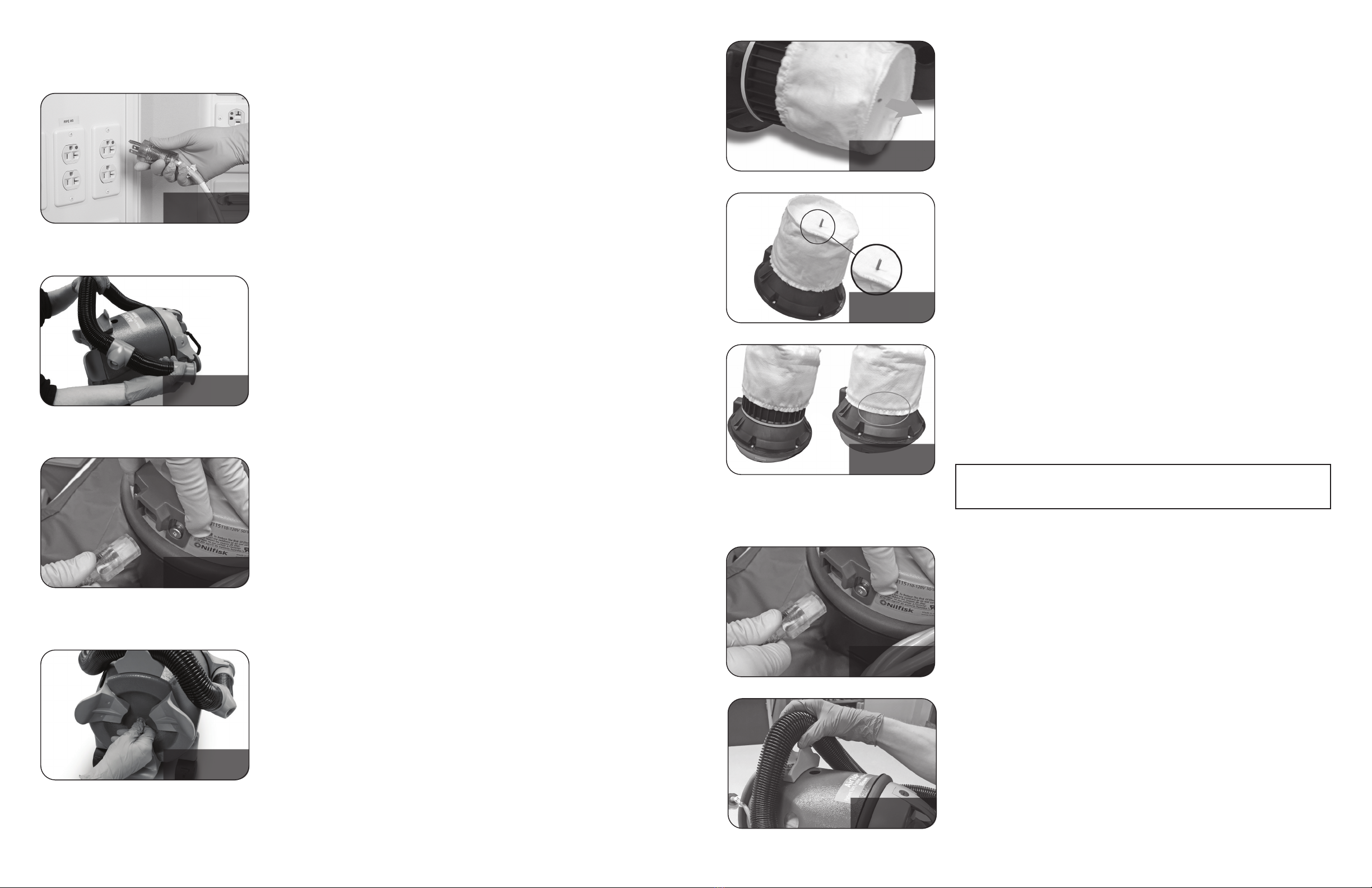
2. Remove the Wedges if present by grasping the corner and slowly
rotating out.
3. Set the sending and receiving support surfaces as close together as
possible. Ensure the bed brakes are locked.
4. Set the receiving support surface slightly above, but no more than
one inch above the sending support surface.
5. Raise the exterior bed rails.
6. Ensure the patient is centered on the Glide Sheet and the support
surface.
WARNING: Before inating, ensure lines and tubing are free to
move with the patient and that nothing obstructs the area over which
the Glide Sheet will pass. Ensure that the Hose will move freely with the
Glide Sheet.
7. While closely observing the patient, push the Power Button on the
Hose.
8. Allow the Glide Sheet to fully inate.
WARNING: Ensure the Glide Sheet is fully inated prior to
transfer. If the Glide Sheet is not fully inated, injury to the patient or
caregiver could occur or the Glide Sheet may not perform as expected.
9. Ensure the patient’s head and feet are supported.
10. With a minimum of one caregiver on each side, the caregiver on the
sending surface gently pushes the patient toward the receiving side.
11. The caregiver on the receiving surface grasps the handles and helps
glide the patient into position.
12. Ensure the patient is fully on the support surface.
13. Turn the Booster Pump off by pressing the Power Button.
14. Allow the Glide Sheet to fully deate and smooth out any wrinkles
in the Glide Sheet or Microclimate Body Pad.
15. Slightly separate the receiving and sending surfaces until the rail on
the receiving surface can be accessed.
16. Raise the bed rails.
17. Use the Hanging Clip to hang the Booster Pump from the patient
transport surface.