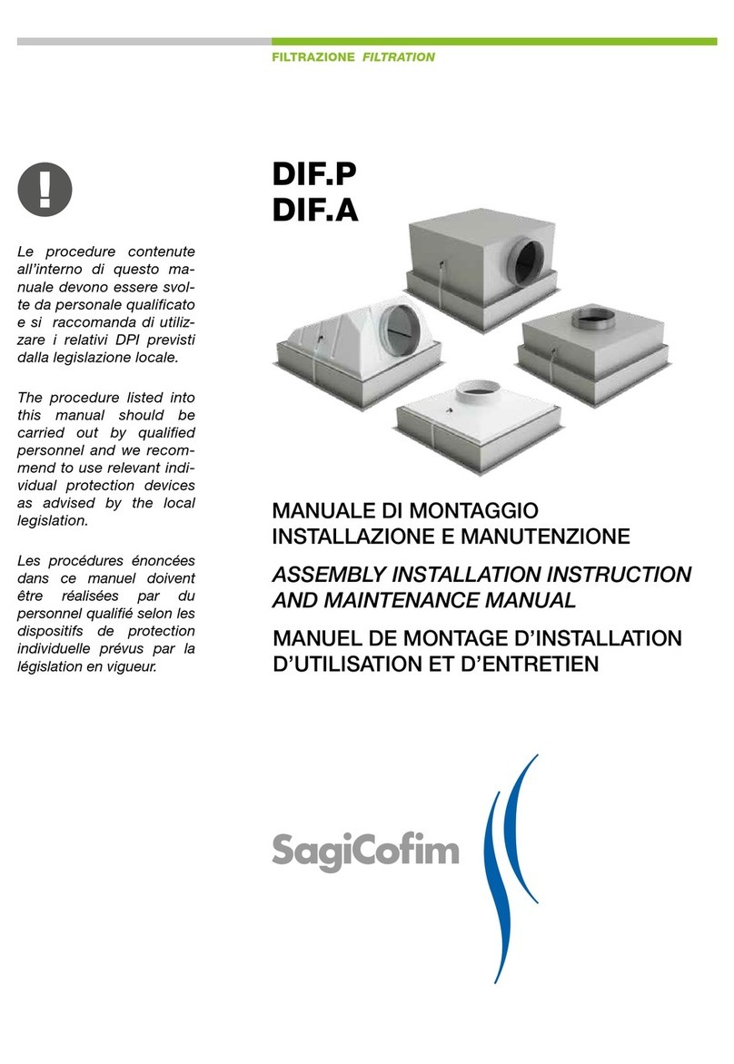
SagiCofim HTE 400 Installer manual

FIRE PROTECTION
HTE 400
Rectangular re damper
UNI EN 1366-2 Certication
UNI EN 13501-3 Classication
ASSEMBLY INSTALLATION
AND MAINTENANCE MANUAL
The procedure listed into this manual should be carried out
by qualied personnel and we recommend to use relevant in-
dividual protection devices as advised by the local legislation.

SE_20200507_HTE 400_M
2
HT400 Rectangular re damper - UNI EN 1366-2 Certied - UNI EN 13501-3 Classied
HTE 400
Depending on the type of wall, the installation and sealing
procedures described in this manual, and in accordance with
the tested conguration, must be respected at all time.

SE_20200507_HTE400_M 3
HT400 Rectangular re damper - UNI EN 1366-2 Certied - UNI EN 13501-3 Classied
Summary
1.0
1.1
1.2
1.3
1.4
1.5
1.6
2.0
2.1
2.2
2.3
2.4
3.0
3.1
3.2
3.3
4.0
4.1
4.2
4.3
4.4
4.5
4.6
4.7
Types and Congurations
HTE 400 + BELIMO - Conguration B2 / B6 / C6 / C8 / F1 / F3
HTE 400 + SCHISCHEK - Conguration X1 / X3 / X5
HTE 400 + Mechanical release with manual reset - Conguration M1 / M2 / M3
HTE 400 + Magnet - Conguration E1 / E3 / E5 / E7
HTE 400 + CO2 driven release - Conguration G0
Damper weight / Actuator weigh
Individual damper installation
General informations
Installation on autoclaved aerated concrete walls
Installation on hard horizontal surfaces made of high-density reinforced concrete
Installation on vertical plasterboard bases
Installation of dampers side-by-side or in multi-sections
Side-by-side installation on autoclaved aerated concrete walls
Side-by-side installation on vertical plasterboard bases
Special case: installation on ducting with dimensions > 2000 mm x 800 mm
Procedures for replacing actuators and accessories
Mechanical release with manual reset / magnet - Thermal fuse replacement
Dampers with BELIMO electric actuator model BFL / BFN / BAT thermal fuse
Dampers with BELIMO electric actuator model BF/BAE thermal fuse
Dampers with SCHISCHEK electric actuator / ExProTT - InProTT thermal fuse
Dampers with mechanical release and manual reset
Dampers with normally non-energised magnets
Dampers with CO2-driven release
page
page
page
page
page
page
page
page
page
page
page
page
page
page
page
page
page
page
page
page
page
page
page
page
4
4
6
7
8
10
12
13
13
14
16
18
22
24
26
30
31
31
32
34
36
38
40
42

SE_20200507_HTE 400_M
4
HT400 Rectangular re damper - UNI EN 1366-2 Certied - UNI EN 13501-3 Classied
The dimensions shown on all diagrams are expressed in [mm]
CONFIGUARATION
• B2 - BF24T
• B6 - BF230T
• C6 - BFN24T
• C8 - BFN230T
• F1 - BFL24T
• F3 - BFL230T
400 [± 5 ext.]
165
125
Wall limit
16570
Ysup.
Yinf.
H + 68
BO BO
DIMENSIONS OF BELIMO ELECTRIC SERVO MOTORS
H[mm]
150 200 ≥ 200
BFL 20 0 0 0
BFN 50 20 0 0
BF 60 30 0 0
Yinf [mm] Ysup [mm]
For dampers with height > 400 mm blade overhang is:
H - 400 mm
2
MS = Minimum space for servicing servo motor equivalent to 200 mm
BO = Blade overhang
FAIL-CLOSE LOGIC
- Working conditions/powered motor ÎDAMPER OPEN
- Normal conditions or failure/motor not powered ÎDAMPER CLOSED
1.0 Congurations and types
1.1 HTE 400 + BELIMO - Conguration B2 / B6 / C6 / C8 / F1 / F3
W [± 2 int.]36 36
70
MS
H [± 2 int.]36 36

SE_20200507_HTE400_M 5
HT400 Rectangular re damper - UNI EN 1366-2 Certied - UNI EN 13501-3 Classied
ACTUATOR SELECTION ACCORDING DAMPER SIZE
800
750
700
650
600
550
500
450
400
350
300
250
200
150
150
200
250
300
350
400
450
500
550
600
650
700
750
800
850
900
950
1000
1050
1100
1150
1200
1250
1300
1350
1400
1450
1500
W
H
BFL BFN BF
AC 230 V, open-close
S1 S2 S3 S4 S5 S6
<5° <80°
21
N L1
BAE72B-S
Tf1 Tf2 Tf3 LED
Cable colours:
1 = blue
2 = brown
S1 = white
S2 = white
S3 = white
S4 = white
S5 = white
S6 = white
B2 - BF 24T
Servo motor 90°, AC / DC 24 V, 18/12 Nm, with BAE
B6 - BF 230T
Servo motor 90°, AC 230 V, 18 Nm / 12 Nm, with BAE
C6 - BFN 24T
Servo motor 90°, AC / DC 24 V, 9 Nm / 7 Nm, with BAT
F1 - BFL 24T
Servo motor 90°, AC / DC 24 V, 4 Nm / 3 Nm, with BAT
C8 - BFN 230T
Servo motor 90°, AC 230 V, 9 Nm / 7 Nm, with BAT
F3 - BFL 230T
Servo motor 90°, AC 230 V, 4 Nm / 3 Nm, with BAT
Tf Tf LED
BAT
S1 S2 S3 S4 S5 S6
<5° <80°
21
–+
T
~
AC/DC 24 V, open-close Cable colours:
1 = black
2 = red
S1 = violet
S2 = red
S3 = white
S4 = orange
S5 = pink
S6 = gray
Tf: thermal
fuse
Tf Tf LED
BAT
S1 S2 S3 S4 S5 S6
<5° <80°
21
NL1
AC 230 V, open-close Cable colours:
1 = blue
2 = brown
S1 = violet
S2 = red
S3 = white
S4 = orange
S5 = pink
S6 = gray
Tf: thermal
fuse
S1 S2 S3 S4 S5 S6
<5° <80°
21
–+
T
~
BAE72B-S
Tf1 Tf2 Tf3 LED
AC/DC 24, open-close Cable colours
1 = black
2 = white
S1 = white
S2 = white
S3 = white
S4 = white
S5 = white
S6 = white
1.1 HTE 400 + BELIMO - Conguration B2 / B6 / C6 / C8 / F1 / F33
Electrical installation

SE_20200507_HTE 400_M
6
HT400 Rectangular re damper - UNI EN 1366-2 Certied - UNI EN 13501-3 Classied
ON-OFF
3 position - servo control + Ex-i safe spark circuit
Spring return ~10 s standard wiring
Spring return ~3 s additional wiring pin n°5
<5° <85°
.. Pro-TT
Pulsante
di prova
°C
12
ab
PA
345 11
24...240 VAC/DC
6 7 8 9 10 11
–+
~~
ELECTRICAL INSTALLATION
DIMENSIONS OF SCHISCHEK ELECTRIC SERVO MOTORS
H[mm]
150 200 ≥ 250
15BF 50 25 0 0
Yinf [mm] Ysup [mm]
Dati valid for model InMax, RedMax, ExMax 15BF
1.2 HTE 400 + SCHISCHEK - Conguration X1 / X3 / X5
CONFIGURATION
• X5 - InMax 15BF + InPro-TT
• X1 - RedMax 15BF + ExPro-TT
• X3 - ExMax 15BF + ExPro-TT
FAIL-CLOSE LOGIC
- Working conditions/powered motor ÎDAMPER OPEN
- Normal conditions or failure/motor not powered ÎDAMPER CLOSED
W [± 2 int.]36 36
100
MS
H [± 2 int.]36 36
Ysup.
Yinf.
H + 68
400 [± 5 ext.]
165
125
Wall limit
16570
BO BO
The dimensions shown on all diagrams are expressed in [mm]
For dampers with height > 400 mm blade overhang is:
H - 400 mm
2
MS = Minimum space for servicing servo motor equivalent to 200 mm
BO = Blade overhang

SE_20200507_HTE400_M 7
HT400 Rectangular re damper - UNI EN 1366-2 Certied - UNI EN 13501-3 Classied
DIMENSIONS OF MECHANICAL RELEASE SYSTEMS WITH MANUAL RESET
H[mm]
150 200 250 300 350 400 ≥ 450
50 125 100 75 50 25 0 0
Yinf [mm] Ysup [mm]
SIGNAL MICROSWITCH
18
20
22
5451.5
105.5
19
3
30.8
4.2x7.2
14.2
28
41.5
16.5
5.4
30.8
24.2
FR530 1NC + 1NO
1.3 HTE 400 + MECHANICAL RELEASE WITH MANUAL RESET
Conguration M1 / M2 / M3
(M3 conguration shown in the drawing)
CONFIGURATION
• M 1 - NO signal Micro
• M 2 - WITH 1 signal Micro FR 530
• M 3 - WITH 2 signal Micro FR 530
For dampers with height > 400 mm blade overhang is:
H - 400 mm
2
MS = Minimum space for servicing servo motor/mechanism 200 mm
BO = Blade overhang
FAIL-CLOSE LOGIC
- Working conditions / torsion spring loaded / lever in horizontal position ÎDAMPER OPEN
- Normal conditions or failure / torsion spring unloaded / lever in vertical position ÎDAMPER CLOSED
The dimensions shown on all diagrams are expressed in [mm]
Ysup.
Yinf.
H + 68
400 [± 5 ext.]
165
125
Wall limit
16570
W [± 2 int.]36 36
80
MS
H [± 2 int.]36 36
BO BO

SE_20200507_HTE 400_M
8
HT400 Rectangular re damper - UNI EN 1366-2 Certied - UNI EN 13501-3 Classied
CONFIGURATION
• E1 - Magnet 230V normally de-energized
1 Micro FR530 connected to the reset lever
1 Micro FR5A1 connected to fuse link
• E3 - Magnet 24V normally de-energized
1 Micro FR530 connected to the reset lever
1 Micro FR5A1 connected to fuse link
• E5 - Magnet 230V normally de-energized
1 Micro FR5A1 connected to fuse link
• E7 - Magnete 24V normally de-energized
1 Micro FR5A1 connected to fuse link
DIMENSIONS OF RELEASE SYSTEMS WITH MAGNETS
H[mm]
150 200 250 300 350 400 ≥ 450
50 125 100 75 50 25 0 0
Ysup [mm] Yinf [mm]
1.4 HTE 400 + MAGNET - Conguration E1 / E3 / E5 / E7
(conguration shown in the drawing E1 / E3)
MS = Minimum space for servicing servo motor/mechanism 200 mm
BO = Blade overhang
FAIL-CLOSE LOGIC
- Working conditions /
torsion spring loaded / lever in horizontal position / magnet powered ÎDAMPER OPEN
- Normal conditions or failure /
torsion spring unloaded / lever in vertical position / magnet not powered ÎDAMPER CLOSED
Ysup.
Yinf.
H + 68
400 [± 5 ext.]
165
125
Wall limit
16570
W [± 2 int.]36 36
80
MS
H [± 2 int.]36 36
BO BO
The dimensions shown on all diagrams are expressed in [mm]
For dampers with height > 400 mm blade overhang is:
H - 400 mm
2

SE_20200507_HTE400_M 9
HT400 Rectangular re damper - UNI EN 1366-2 Certied - UNI EN 13501-3 Classied
TECHNICAL DATA
Voltage 24/230 V
Power < 3.5 W
Thermal class of the coil 155 °C (F)
Duty cycle 100%
Minimum strength guaranteed > 680 N
Degree of the rotection according to NF EN 60-529 IP 65
Rust protection according to ISO 9227 24 HBS
Operating temperature -20 °C ÷ 100 °C
Weight 350 g
Supply S = 0.22 mm2
Total length: 100 mm
Ø 45
M5
37,5
12
FR5A1 1NO + 1NC
Ø 12
30.830.8
3
20
22
24.2
Ø 8
21
12.2
51.5
72.5
14.2
4.2x7.2
SIGNAL MICROSWITCH FUSE LINK MICROSWITCH
18
20
22
5451.5
105.5
19
3
30.8
4.2x7.2
14.2
28
41.5
16.5
5.4
30.8
24.2
FR530 1NC + 1NO
ELECTROMAGNET
1.4 HTE 400 + MAGNET - Conguration E1 / E3 / E5 / E7
Micro - Electromagnet

SE_20200507_HTE 400_M
10
HT400 Rectangular re damper - UNI EN 1366-2 Certied - UNI EN 13501-3 Classied
DIMENSIONS OF RELEASE SYSTEMS WITH CO2
H[mm]
150 >150 150 200 250 300 350 400 ≥ 450
25 0 150 125 100 75 50 25 0 5
Yinf [mm] Ysup [mm] BOc[mm]
1.5 HTE 400 + CO2
DRIVEN RELEASE- Conguration G0
CONFIGURATION
• G0 - CO2
Driven release
2 Micro FD531
FAIL-CLOSE LOGIC
- Working conditions /
torsion spring loaded / lever in horizontal position / piston not powered ÎDAMPER OPEN
- Normal conditions or failure /
torsion spring unloaded / lever in vertical position / CO2release at piston ÎDAMPER CLOSED
W [± 2 int.]36 36
180
MS
H [± 2 int.]36 36
Ysup.
Yinf.
H + 68
400 [± 5 ext.]
165
125
Wall limit
16570
BO BO
BOc
The dimensions shown on all diagrams are expressed in [mm]
MS = Minimum space for servicing servo motor/mechanism 200 mm
BO = Blade overhang
For dampers with height > 400 mm blade overhang is:
H - 400 mm
2

SE_20200507_HTE400_M 11
HT400 Rectangular re damper - UNI EN 1366-2 Certied - UNI EN 13501-3 Classied
MATERIAL
1. Bushing Nickel-plated brass CW 614N
2. Spring Inox 303 / S.S. 303
3. O-Ring 4087 Viton 75 SH
4. O-Ring 3125 Viton 75 SH
5. /4” BSP flare x /8NPT nipple Nickel-plated brass CW 614N
6. O-Ring 112 Viton 75 SH
7. Pin Nickel-plated brass CW 614N
8. Bushing Z 140 galvanised nickel-plated brass
CW 614N
TECHNICAL DATA
Intervention pressure 3 bar
Max pressure work 250 bar
Minimal pressure of pneumatic testing 2,5 bar
Max pressure of pneumatic testing 300 bar
Desing temperature x CO2, N2 -20 +200 °C
Desing temperature for vapor -40 +140 °C
Weight 0,558 Kg
For vapor supply, EPDM O-ring are used
69
90°
6
5
8
7
4
3
2
1
Ø10
Ø4.5
100
91
89
20
22
171351
8
CO2RELEASE Mod. LNMTOTT33NICH
SIGNAL MICROSWITCH
18
20
22
5451.5
105.5
19
3
30.8
4.2x7.2
14.2
28
39.4
31.1
5.4
30.8
24.2
FD531 1NO + 1NC
1.5 HTE 400 + CO2
DRIVEN RELEASE- Conguration G0
CO2release - Signal microswitch

SE_20200507_HTE 400_M
12
HT400 Rectangular re damper - UNI EN 1366-2 Certied - UNI EN 13501-3 Classied
ACTUATOR WEIGHT BELIMO
[Kg]
BFL 1,5
BFN 2,0
BF 3,5
DAMPER WEIGHT TABLE
H [mm] Weight [Kg]
800 14,8 16,3 19,2 22,1 25,0 27,9 30,9 33,8 36,7 39,6 42,5 45,4 48,4 51,3 54,2
750 14,1 15,5 18,3 21,1 23,9 26,7 29,5 32,3 35,1 37,9 40,7 43,5 46,3 49,1 51,9
700 13,4 14,7 17,4 20,1 22,8 25,5 28,2 30,9 33,6 36,2 38,9 41,6 44,3 47,0 49,7
650 12,7 14,0 16,6 19,1 21,7 24,3 26,8 29,4 32,0 34,6 37,1 39,7 42,3 44,8 47,4
600 12,0 13,2 15,7 18,1 20,6 23,0 25,5 28,0 30,4 32,9 35,3 37,8 40,2 42,7 45,1
550 11,3 12,5 14,8 17,1 19,5 21,8 24,2 26,5 28,8 31,2 33,5 35,9 38,2 40,5 42,9
500 10,6 11,7 13,9 16,1 18,4 20,6 22,8 25,0 27,3 29,5 31,7 33,9 36,2 38,4 40,6
450 9,9 10,9 13,0 15,2 17,3 19,4 21,5 23,6 25,7 27,8 29,9 32,0 34,1 36,2 38,4
400 9,2 10,2 12,2 14,2 16,2 18,1 20,1 22,1 24,1 26,1 28,1 30,1 32,1 34,1 36,1
350 8,5 9,4 11,3 13,2 15,0 16,9 18,8 20,7 22,6 24,4 26,3 28,2 30,1 31,9 33,8
300 7,8 8,6 10,4 12,2 13,9 15,7 17,5 19,2 21,0 22,7 24,5 26,3 28,0 29,8 31,6
250 7,1 7,9 9,5 11,2 12,8 14,5 16,1 17,8 19,4 21,1 22,7 24,4 26,0 27,6 29,3
200 6,4 7,1 8,7 10,2 11,7 13,2 14,8 16,3 17,8 19,4 20,9 22,4 24,0 25,5 27,0
150 5,7 6,4 7,8 9,2 10,6 12,0 13,4 14,9 16,3 17,7 19,1 20,5 21,9 23,4 24,8
150 200 300 400 500 600 700 800 900 1000 1100 1200 1300 1400 1500
W [mm]
1.6 Damper weight / Actuator weight
[Kg]
Manual release 2,0
Magnet 3,0
CO2 release 3,0
ACTUATOR WEIGHT SCHISCHEK
Aluminium Stainless Steel
[Kg] [Kg]
InMax 15BF 3,5 7,0
RedMax 15BF 3,5 7,0
ExMax 15BF 3,5 7,0

SE_20200507_HTE400_M 13
HT400 Rectangular re damper - UNI EN 1366-2 Certied - UNI EN 13501-3 Classied
2.0 Individual damper installation
2.1 General information
NEUTRAL POSITION OF THE MECHANISM
2.2)
Brick and concrete
walls
2.3)
Hard horizontal
surfaces in
reinforced concrete
2.4)
Plasteboard walls
• Only valid for dimensions from 150 x 150
to 1500 x 800 mm;
• Storage (dry place with temperature
between 0°C and 50°C);
• Functional product test before instal-
lation (implement a complete open/
close cycle without power);
• Storage for long periods (after 6
months check integrity and function-
al operation before installation with/
without power - as required).
• If equipped with a mechan-
ical release system with
manual reset or magnet
an inspection hatch on the
ducting side which is 250
mm in length must be pro-
vided.

SE_20200507_HTE 400_M
14
HT400 Rectangular re damper - UNI EN 1366-2 Certied - UNI EN 13501-3 Classied
2.2 Installation on autoclaved aerated concrete walls
In walls being built to a thickness of 100 mm include an open-
ing with width and height 90 mm larger than the nominal
damper measurements.
Apply a layer of adhesive mortar to the bottom of
the opening.
The HTE400 re damper can only protect against re and smoke if it is installed correctly in approved walls.
IF THE WALL HAS LESS RESISTANCE THAN THE FIRE DAMPER, THE DAMPER RESISTANCE WILL BE REDUCED TO
THAT OF THE BRICKWORK.
PHASE 1
PHASE 2
ASSEMBLY PROCEDURE
W + 90 mm
100 mm
H + 90 mm
mortar

SE_20200507_HTE400_M 15
HT400 Rectangular re damper - UNI EN 1366-2 Certied - UNI EN 13501-3 Classied
Position the re damper in the centre of the opening.
NB: With thicker walls comply with the wall limits indicated on the damper and install it as shown in the diagram.
E
E
Limite di
muratura
Limite di
muratura
Wall Limit Information
Use adhesive mortar designed for bricklaying to ll in the gap
around the re damper.
Adhesive mortar
or class M10
EN 998-2 mortar
Support bracket
Support brackets are only provided for larger dampers
[≥1000 x 800 mm].
PHASE 5
PHASE 3
PHASE 4
2.2 Installation on autoclaved aerated concrete walls

SE_20200507_HTE 400_M
16
HT400 Rectangular re damper - UNI EN 1366-2 Certied - UNI EN 13501-3 Classied
To install the re damper the horizontal support must have a
suitable opening. The opening must have a width and height
120 mm larger than the nominal damper measurements, and
a depth of 150 mm.
To facilitate the installation of the re damper place
a115-mm spacer in each of the four corners (see di-
agram).
PHASE 2
altezza preforo =
H + 120 mm
150 mm
base preforo =
W + 120 mm
115
2.3 Installation on hard horizontal surfaces
made of high-density reinforced concrete
The HTE400 re damper can only protect against re and smoke if it is installed correctly in an approved horizontal
support.
IF THE WALL HAS LESS RESISTANCE THAN THE FIRE DAMPER, THE DAMPER RESISTANCE WILL BE REDUCED TO
THAT OF THE BRICKWORK.
ASSEMBLY PROCEDURE
PHASE 1

SE_20200507_HTE400_M 17
HT400 Rectangular re damper - UNI EN 1366-2 Certied - UNI EN 13501-3 Classied
Use class M10 EN 998-2 mortar to ll in around the horizontal
support and ensure there are no gaps.
Once set remove the spacers. The class M10 EN
998-2 mortar must ll the entire perimeter be-
tween the damper and the wall.
PHASE 3
PHASE 4
Adhesive mortar
or class M10 EN 998-2 mortar
2.3 Installation on hard horizontal surfaces
made of high-density reinforced concrete
Support brackets are only provided for larger damp-
ers [≥1000 x 800 mm].

SE_20200507_HTE 400_M
18
HT400 Rectangular re damper - UNI EN 1366-2 Certied - UNI EN 13501-3 Classied
Start by tting the rst two wall plates on the structure.
PHASE 2
50 mm25
==
structureplates
In walls being built to a thickness of 100 mm, verti-
cal metal structures must have a suitable opening
for the installation of re dampers. The opening must
have a width and height 130 mm larger than the
nominal damper measurements.
W + 130 mm
H + 130 mm
max spacing
625 mm
A : A
section
A : A
50 mm
2.4 Installation on vertical plasterboard bases
The HTE400 re damper can only protect against re and smoke if it is installed correctly in an approved vertical plas-
terboard support.
IF THE WALL HAS LESS RESISTANCE THAN THE FIRE DAMPER, THE DAMPER RESISTANCE WILL BE REDUCED TO
THAT OF THE BRICKWORK.
ASSEMBLY PROCEDURE
PHASE 1

SE_20200507_HTE400_M 19
HT400 Rectangular re damper - UNI EN 1366-2 Certied - UNI EN 13501-3 Classied
Proceed by lling the structure with
50 mm thick mineral wool with a
density of 100 kg/m3.
Close the structure by tting the two
plates.
Seal the opening in the structure.
50 mm25
==
25
==
50 mm 100 mm
25
==
LANA MINERALE
LANA MINERALE
PHASE 3 PHASE 4 PHASE 5
2.4 Installation on vertical plasterboard bases

SE_20200507_HTE 400_M
20
HT400 Rectangular re damper - UNI EN 1366-2 Certied - UNI EN 13501-3 Classied
PHASE 6
Once the re damper is housed in the opening with the closed blades positioned in the centre of the wall secure it using 4 brackets
(to be ordered separately).
Secure using plasterboard screws.
Limite di
muratura
Limite di
muratura
Wall Limit Information
Support bracket
NB: With thicker walls comply with the wall
limits indicated on the damper and install it as
shown in the diagram.
2.4 Installation on vertical plasterboard bases
Table of contents
Other SagiCofim Fire And Smoke Damper manuals
Popular Fire And Smoke Damper manuals by other brands

BESA
BESA TB/001 Technical bulletin

Mandik
Mandik VCDM Installation, operation, maintenance and service manual

actionair
actionair DWFX-F installation guide

SMAY
SMAY KTS-O-E installation manual

Greenheck
Greenheck CRD-300WT Installation, operation and maintenance manual

Lindab
Lindab RECTANGULAR Series Installation booklet