SAI HVAC Compact Comfort VAV12 Manual

1
Copyright. SAI HVAC 2021-2022 TM_VRAF_VAV12.21.003
Compact Comfort by SAI HVAC
VAV12 Controls Install Manual
Series 2

2
Copyright. SAI HVAC 2021-2022 TM_VRAF_VAV12.21.003
Publisher
SAI HVAC
Phone 1300 844 429
Internet www.compactcomfort.com
Revision V21.3
This Technical Manual describes the installation and operation of the Compact Comfort VAV12 controls system
and air conditioning maintenance for the installer.
Copyright
This publication is Copyright © 2021-2022 SAI HVAC. All rights reserved. No part of this publication may be
reproduced, stored in any retrieval system or transmitted, in any form or by any means, electronic,
mechanical, photocopying, recording or otherwise, without the prior written permission of SAI HVAC.
Disclaimer
SAI HVAC reserves the right to make changes and improvements to any of the products described in this
document without prior notice. Under no circumstances shall SAI HVAC be responsible for any loss of income
or any special, incidental, consequential or indirect damages howsoever caused.
Warranty
The contents of this document are provided “as is”. Except as required by applicable law, no warranties of any
kind, either express or implied, including, but not limited to, the implied warranties of merchantability and
fitness or a particular purpose, are made in relation to the accuracy, reliability or contents of this document,
SAI HVAC reserves the right to revise this document or withdraw it at any time without prior notice.
Sourcing
Proudly designed and manufactured in Australia by SAI HVAC, an independent Australian-owned company.

3
Copyright. SAI HVAC 2021-2022 TM_VRAF_VAV12.21.003
Contents
1. About your VAV12 Controls System ...................................................................................................................4
1.1 Compatibility ................................................................................................................................................4
1.2 Simple and Upgradable ................................................................................................................................4
1.3 Plug & Play....................................................................................................................................................4
1.4 Html User Interface ......................................................................................................................................4
1.5 Remote Access .............................................................................................................................................4
2. How to Connect to the System...........................................................................................................................5
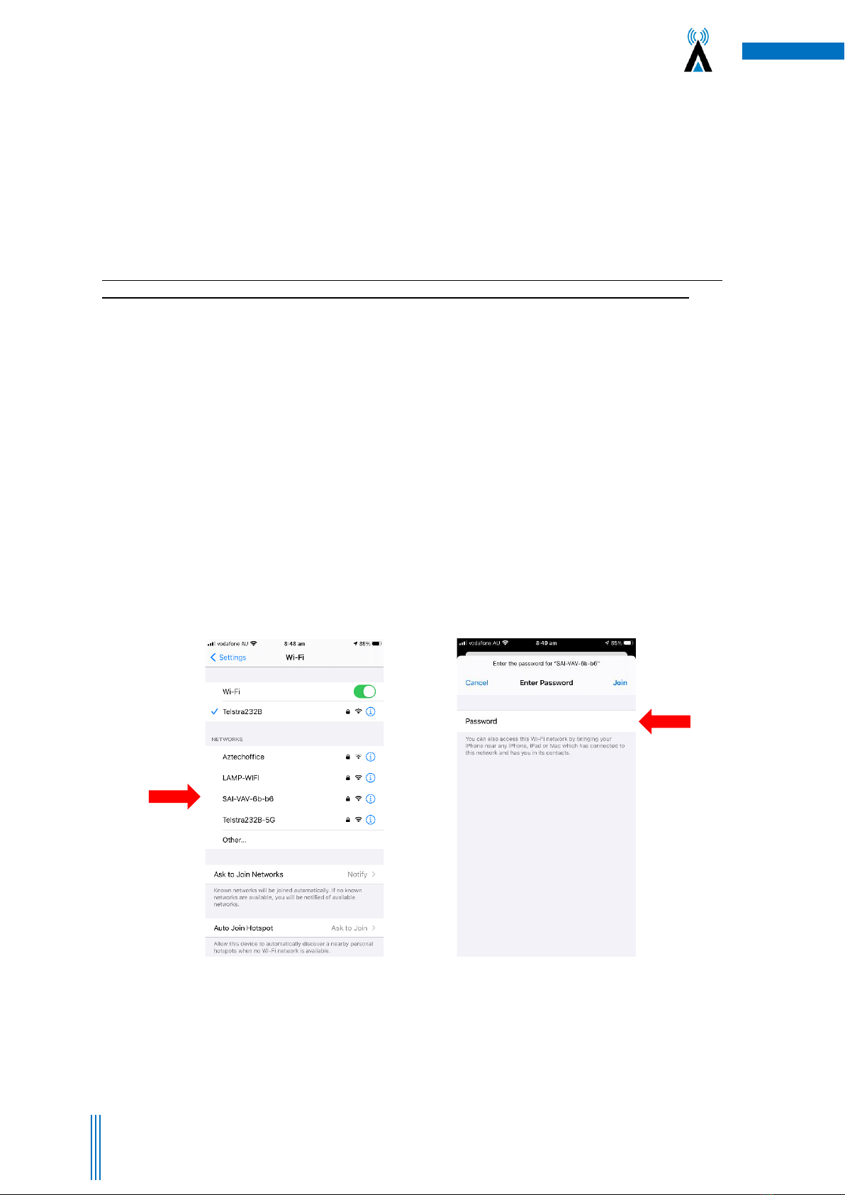
2.1 Direct Connection via Wi-Fi..........................................................................................................................5
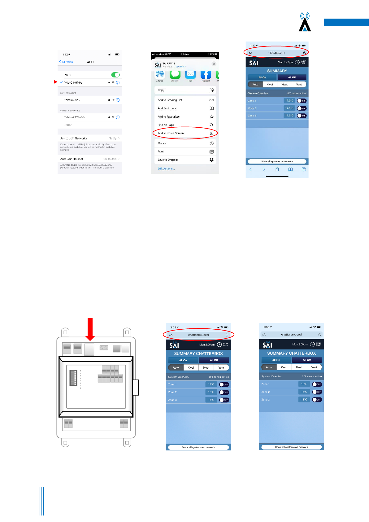
2.2 Direct Connection via your LAN ...................................................................................................................6
2.3 Connection via Mothership (Recommended) ..............................................................................................7
3.4 Using the Mothership Cloud Service ............................................................................................................7
3. VAV12 Operating Instructions Using the User Interface ....................................................................................8
3.1 Changing the System Mode .........................................................................................................................8
3.2 Notes on Dynamic Energy Recovery ............................................................................................................8
3.3 Set the Optional Countdown Timer .............................................................................................................9
3.4 Optional “Cooling” and “Economy” Settings................................................................................................9
3.5 Setting the Global time schedule (whole system)......................................................................................10
3.6 Setting Individual zones time schedules. ...................................................................................................10
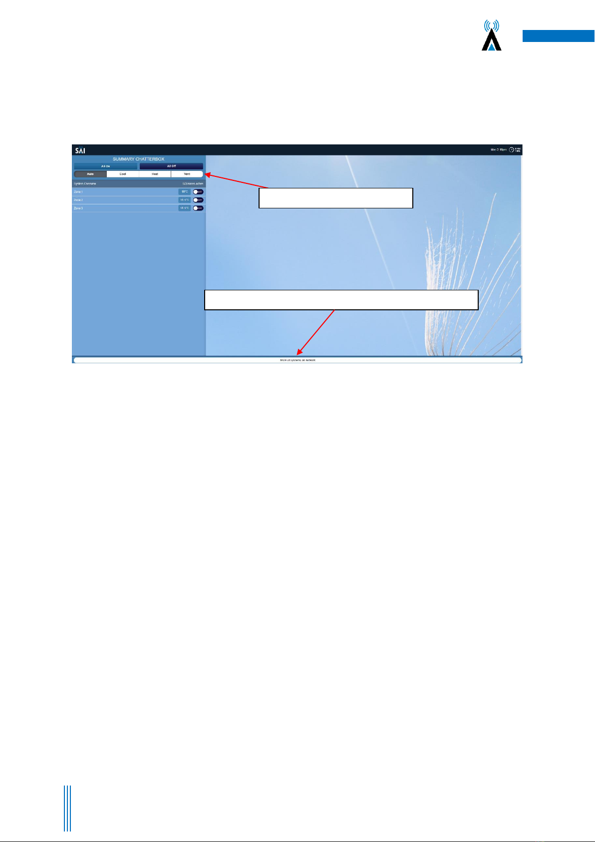
3.7 Browse to Other Systems ...........................................................................................................................11
3.8 Adjusting the Settings on a Zone................................................................................................................11
4. System Diagnostics ...........................................................................................................................................12
5. SAI HVAC VAV12 Controls.................................................................................................................................14
5.1 SAI HVAC VAV12 Navigator ........................................................................................................................14
5.1.1 Turning the System ON and OFF.........................................................................................................14
5.1.2 Turning a Zone ON and OFF ................................................................................................................14
5.1.3 Browsing to a Zone .............................................................................................................................15
5.1.4 Changing the Temperature in a Zone .................................................................................................15
5.2 Using the Single Button Capacitive Touch Room Controller ......................................................................15
5.3 Surface 7 Touchpad....................................................................................................................................16
5.4 Surface 5 Touchpad....................................................................................................................................17
6. Manufacturers Recommendations...................................................................................................................18
6.1 Return Air Filter Cleaning ...........................................................................................................................18
6.2 Outdoor Unit ..............................................................................................................................................18
6.3 Vents & Return Air Grill..............................................................................................................................18
6.4 Controllers..................................................................................................................................................18
7. Troubleshooting................................................................................................................................................19
8. Warranty...........................................................................................................................................................19

4
Copyright. SAI HVAC 2021-2022 TM_VRAF_VAV12.21.003
1. About your VAV12 Controls System
1.1 Compatibility
A User Interface (UI) has been developed to simplify the commissioning, use and change of operating
parameters for the SAI HVAC range of products. A click of “Other Systems” at the top of the user page switches
between the various SAI HVAC systems.
1.2 Simple and Upgradable
The VAV12 architecture allows for remote upgrade of many features so as development continues new
features can be added via an internet connection.
1.3 Plug & Play
You can also add one of the other SAI HVAC systems such as climate control and lighting control. SAI HVAC
systems are “plug and play” you don’t need to call in a programmer, automation specialist or specialist
technician. Once the systems are connected on the same LAN they recognise each other and the appropriate
interface is loaded without the need for you to do anything.
1.4 Html User Interface
The html user interface can be used on most devices with a browser from a Smartphone or tablet to PC. The
display results vary slightly depending on your device and browser type used. Many people choose the iPad
mini as their UI platform but a laptop, PC or even your iPhone/Samsung can be used to control your SAI HVAC
product.
1.5 Remote Access
Providing your system is connected to a Local Area Network (LAN) with an internet connection, The system
allows you to remotely access your SAI HVAC systems remotely. This feature can be convenient for many
reasons and is achieved by a secure connection through the SAI HVAC Mothership (MS) global server. You first
login to mothership and then browse to your various SAI HVAC devices connected to your mothership account.
Your mothership account can provide access to your SAI HVAC devices at multiple locations so if you are a
building manager you can have access to all your sites at your fingertips through this one convenient and
simple access point.

5
Copyright. SAI HVAC 2021-2022 TM_VRAF_VAV12.21.003
Figure 1 –Select SAI-VAV network in
Wi-Fi settings
Figure 2 –Enter the password –
“chatterbox”
2. How to Connect to the System
There are three different methods for connecting to the AC system. The method you choose will depend on
your location and the type of installation you are working on. Although you can connect to the inbuilt Wi-Fi
(see 2.1) a LAN connection is RECOMMENDED for optimal performance for the client (see 2.2)
2.1 Direct Connection via Wi-Fi
NOTE: The on board Wi-Fi is for use when commissioning the system and only when no LAN connection is
available. Some warranty terms are affected when connecting using only this Wi-Fi service solution.
Each VAV12 controls system can create its own network via Wi-Fi. This means you can connect the clients
smart device/computer to the system. Please note the Wi-fi Dongle supplied must be used.
1. Open your Wi-Fi settings on your device and select the SAI VAV network (Figure 1) –if multiple
chatterboxes ion site check for the Mac Address on the device you are connecting to.
2. The Password is “chatterbox”(Figure 2)
3. Once connected to the controls network you can open your browser and browse to the system IP
address 192.168.2.11
4. You may wish to bookmark the page or add a link to your home screen on your device, so that you
can press the link instead of having to refer back to the IP address each time you wish to connect.
(Figure 4)
5. Direct connection requires your personal device/PC to be within range of the controls network. As
this range can vary significantly depending on building conditions, the preferred method of
connection is via an ethernet cable to the Local Area Network (LAN)

6
Copyright. SAI HVAC 2021-2022 TM_VRAF_VAV12.21.003
Figure 3 –Logged onto
network
Figure 4 –Type IP address into
browser & add to home screen or
book mark
Figure5 –User Interface launches
2.2 Direct Connection via your LAN
Connecting the system to the local LAN via a network cable connected from the VAV12 MPM module to the
client’s router or a switch connected to the router is the preferred and best method for regular connection.
You can then access the system from anywhere the client has LAN coverage. This will also give you access to
SAI HVACs Mothership service (see 3.3) (Figure 6)
To check if the VAV12 system is connected to your network type chatterbox.local into your browser, this will
bring up the GUI and allow you access to your system.
NOTE: Some older routers ship with UPNP disabled. You should check the router instruction manual for details on how to check this setting.
Without UPNP enabled, the system cannot connect. Remember that after power failure the router may assign a different IP number to your
system. In this case you will need to scan the network with FING or similar program to find the new IP. It is possible to set a fixed IP in your
router settings however the method varies depending on your router brand and model. Your IT specialist should be able to help. Connecting
your system to your router using a cable gives a level of access control as access can only be achieved by persons or devices having your
LAN access password.
Figure 6 –Connecting
via Ethernet cable
Figure 7 –Type in chatterbox.local
to access the GUI when connected to
your network.
Figure 8 –User Interface Launches.
CS-VAV12-MPM

7
Copyright. SAI HVAC 2021-2022 TM_VRAF_VAV12.21.003
2.3 Connection via Mothership (Recommended)
Providing the clients system is connected to the building LAN and that the LAN has an internet connection, you
can setup an account on the SAI Mothership global server to allow remote connection to the system via MS.
1. Open your browser and browse to https://chatterboxmothership.com.au and click the register
button on the login page. (Figure 9)
2. The client can fill out registration details and we will send their registration name and password
within 24 hours together with instructions on how to access their system via the Mothership.
3. If you are within the LAN, i.e. at home and your device is connected to the same network the
system is running on, there will be a link at the bottom of the log in page titled “Your Local Devices”
with the Mac Address and system description. You can click this link to go straight to the User
Interface without having to log in. (Figure 9)
4. Once you have received notice of your User Name and Password, the client can go to the log in
page, enter the details, then press Login to access their system outside of their LAN.
5. The next screen that launches will have a list of your AC systems. (Figure 10)
6. To access the User interface for any of the systems press the Launch button on the right hand side.
This will launch the interface and you can start to control your device. (Figure 11)
3.4 Using the Mothership Cloud Service
https://chatterboxmothership.com.au
Figure 9 –Welcome/Login/Registration Page.
Note the links at bottom of page when on the
LAN
Figure 10 –Your devices will be listed on the control centre
screen. Press Launch for the device you wish to interact with.
Log in to the cloud service
Register for the service
Your local devices (on your network (LAN)

8
Copyright. SAI HVAC 2021-2022 TM_VRAF_VAV12.21.003
3. VAV12 Operating Instructions Using the User Interface
Please note these instructions are for Desktop or Touchpad viewing, the smart phone will have a similar layout.
1. Open the User interface using the steps mentioned in 2.1, 2.2 or 2.3
2. The Launch page will open. (Figure 11)
3.1 Changing the System Mode
Press the Auto, Heat, Cool or Vent Buttons. (Figure 11)
Auto –Will switch between Heating and Cooling between zones.
Cool –Cooling only setting
Heat –Heating only setting
Vent –Will only circulate ambient air
3.2 Notes on Dynamic Energy Recovery
Your SAI HVAC multi zone temperature control system modulates its output capacity to match the heat load. It
continues to cool or heat individual zones until they reach the target temperature (set point). When all zones
are at target temperature, the refrigeration cycle is switched off. On a system where dynamic energy recovery
is disabled, any room can re-activate cooling or heating when the temperature moves away from set point by
0.5°C. Dynamic energy recovery is a technology designed for structures that include a large central area
surrounded by perimeter rooms. The perimeter rooms lose and gain heat at a much faster rate than the
central area. The reason for this phenomenon is that the portion of external walls and roof to room volume is
significantly higher and the additional thermal mass of the central area reduces the rate at which heat is
gained or lost. The dynamic energy recovery algorithm intervenes when a perimeter zone calls for heating or
cooling, it then measures the return air temperature (positioned din the large central zone) to apply a
proprietary algorithm that calculates the flow needed to slow down the rate at which heat is gained or lost.
The slider allows the user to find the right balance for their home or building between energy reduction and
comfort. The slider moves the point at which the worst performing zone can terminate dynamic energy
recovery and force heating or cooling.
The VAV12 zoning control is a unique part of the SAI HVAC system that provides the ability to dramatically
reduce your energy bills. It is important to note that the average household uses 38% of their power bill on
heating and cooling. It is also important to note that every degree Celsius difference between the inside
temperature and the outside temperature adds 10% to the energy cost for that room. SAI HVAC’s multi zone
temperature control system automatically adjusts the airflow to individual rooms to make sure that cooling
and heating overshot is eliminated. There are 3 additional energy settings that are use adjustable that
Figure 11 –Launch Page
brochure.
Mode Select –Auto, Cool, Heat and Vent
Show All systems on network –Browse to other systems on your LAN network

9
Copyright. SAI HVAC 2021-2022 TM_VRAF_VAV12.21.003
decrease energy use further. This feature is most often used in combination with occupancy sensors. When
applied in this fashion you can move through your home & the system automatically turns on and off as
required.
3.3 Set the Optional Countdown Timer
Slide the “Auto Off” slider to the desired position between 30 & 240 minutes. The Auto Off timer is only used if
you wish the system to run for that period of time and then switch off. The system then requires a re-start.
This feature is designed as a safe guard for properties where the air conditioning can be left on while not
required. (Figure 12). Anytime there is an on event on the system in any zone, the system will continue to
operate. This feature is most often used in combination with occupancy sensors. When applied in this fashion
you can move through your home & the system automatically turns on and off as required.
3.4 Optional “Cooling” and “Economy” Settings
See figure 12 use the slider bar to change this setting.
Figure 12 - The “System Overview Screen”
Auto-OFF Timer –Set your Auto off times here
Schedules –set your time schedules
here
Cooling/Heating Economy sliders

10
Copyright. SAI HVAC 2021-2022 TM_VRAF_VAV12.21.003
3.5 Setting the Global time schedule (whole system)
1. Press “System Overview”
2. Press the “Schedules” button
3. Make sure the Global Schedules switch is selected to ON to activate the global schedules. you can turn these
off by selecting OFF
4. Select from 2 schedules –Schedule A and Schedule B
5. After selecting your schedule, select which days and times you wish to turn on and off your system.
6. Press the “Home” button when you have completed your selections.
3.6 Setting Individual zones time schedules.
1. Press the zone you wish to set the time schedule for. (Figure 14)
2. Press the “Schedules” button (Figure 14)
3. Zone time schedules page launches
4. Select from 2 schedules –Schedule A and Schedule B (Figure 14)
5. After selecting your schedule, select which days and times you wish to turn on and off your zone. (Purple
arrow –Figure 14)
6. Press the “Home” button when you have completed your selections. (Figure 15) or select another zone and
repeat.
Figure 13 –The Global time schedules Page
brochure.
Figure 14 –Zone time schedules page is launched. Set on/off events for the selected zone.
brochure.
Schedules –select from two schedules A+B
Select the day and time to start and stop your system
Home button –returns you to the startup screen
Global schedules ON/OFF switch
Zone Select –select your zone to schedule

11
Copyright. SAI HVAC 2021-2022 TM_VRAF_VAV12.21.003
3.7 Browse to Other Systems
You can use the “Show all systems on network” button to display all SAI HVAC systems installed. You can select
which system you wish to control from here. (Figure 11)
3.8 Adjusting the Settings on a Zone
To change the temperature setpoint in a zone.
1. Select the zone you wish to adjust
2. Adjust either up or down to select the desired temperature
Temperature setpoint slider
Temperature setpoint and
room temperature display
Figure 15 –Zone temperature adjust
brochure.

12
Copyright. SAI HVAC 2021-2022 TM_VRAF_VAV12.21.003
4. System Diagnostics
From the home screen, Click on either the “System Overview” or the “Zone” (Bed1 or Bed 2) to see the system
diagnostics.
Information for the selected zone will show on the right-hand side window (figure 18) and the diagnostic
button will appear in the bottom right corner (figure 19). The diagnostic button will appear in the same place
regardless of which zone you select or if you select “System Overview”. This will launch the diagnostics screen
(figure 20)
Please note: The information shown in the diagnostic page will be specific to the System Overview or the
particular zone selected. There is no system summary page that shows diagnostic information for all zones on
one page.
Figure 18 –Launch Screen
brochure.
Figure 19 –Diagnostics Button
brochure.

13
Copyright. SAI HVAC 2021-2022 TM_VRAF_VAV12.21.003
Figure 20 –Diagnostics Screen
brochure.

14
Copyright. SAI HVAC 2021-2022 TM_VRAF_VAV12.21.003
5. SAI HVAC VAV12 Controls
5.1 SAI HVAC VAV12 Navigator
5.1.1 Turning the System ON and OFF
Press the ON/OFF Button when on the main screen to turn all zones ON or OFF.
5.1.2 Turning a Zone ON and OFF
Press the ON/OFF Button when in the zone screen to turn an individual zone ON or OFF.
Set Button
Navigate Left
Navigate Right
Current Mode
Current Temperature
Navigate Up
On/Off
Navigate Down
Temperature Set Point

15
Copyright. SAI HVAC 2021-2022 TM_VRAF_VAV12.21.003
5.1.3 Browsing to a Zone
Use the left and right arrow buttons to scroll through available zones on your system. Continually scrolling in
one direction will cycle the main screen and available zones
5.1.4 Changing the Temperature in a Zone
Once you are on the zone page you wish to adjust, use the UP arrows to adjust the temperature up and the
DOWN arrow to adjust the temperature down.
5.2 Using the Single Button Capacitive Touch Room Controller
The Single button room controller is an easy to use on / off controller for your room or zone. It has a built in
temperature sensor with a central button for turning a zone on or off. If the zone is switched off, the LED
indicator around the capacitive touch button will be turned off. Otherwise the LED indicator has three
different colours that signify different operations:
a) Green –Indicates the zone is active, but it is not currently needed as the room is at temperature.
b) Blue –indicates the zone is active and running on cooling.
c) Red –Indicates the zone is active and running on heating.

16
Copyright. SAI HVAC 2021-2022 TM_VRAF_VAV12.21.003
5.3 Surface 7 Touchpad
Capacitive Touch Buttons
Page Navigation

17
Copyright. SAI HVAC 2021-2022 TM_VRAF_VAV12.21.003
5.4 Surface 5 Touchpad
The Surface 5 functionality can be directly related back to the GUI information.

18
Copyright. SAI HVAC 2021-2022 TM_VRAF_VAV12.21.003
The air conditioning plant and control system contains no user serviceable parts. Installation, service
and maintenance of these components should be carried out by a suitably qualified technician
6. Manufacturers Recommendations
Regular maintenance will ensure your SAI HVAC system operates at maximum efficiency.
6.1 Return Air Filter Cleaning
Cleaning the filter in the return air grille is recommended every month. Filters may be cleaned by either
vacuum or hand wash in mild detergent. Never operate the air conditioner without the filter. Ensure the filter
is in good condition, if not contact your installer for a replacement filter (a charge will apply).
6.2 Outdoor Unit
Do not place any object in front of the condenser. Keep free of grass, leaves and any other form of debris. This
will allow for proper air flow and ensure unit efficiency.
6.3 Vents & Return Air Grill
Regular cleaning of the return air grill and air vents is recommended. This will prevent build-up of dust and
dirt.
6.4 Controllers
Clean the wall controllers with a dry cloth. Do not use a spray detergent or water.
IMPORTANT: Neon signage will interfere with the operation of Compact Comfort controllers. Do not have
neon lights near Compact Comfort Navigators, Surface product or room controllers as the Electromagnetic
field (EMF) will disrupt the operation of the controllers.
The control circuits for the indoor and outdoor units carry voltages > 240 VAC which can cause serious injury or
death.

19
Copyright. SAI HVAC 2021-2022 TM_VRAF_VAV12.21.003
7. Troubleshooting
Problem
Possible Solution
Air Conditioner has restarted but does not operate
for 4 minutes
The normal operating behaviour to protect the
compressor. Wait until the air conditioner begins
operating.
Operation stops for up to 12 minutes during heating
and a different noise/sound comes from the unit.
The unit has entered defrost mode to melt the frost
which has accumulated on the outdoor unit. This
will take no longer than about 12 minutes so wait
for the unit to resume normal operation. (Frost
accumulates on the outdoor unit when the outdoor
temperature is low and the humidity is high. Water
comes out from the outdoor unit).
The air conditioner does not operate.
Has the mode been set correctly?
Is at least one zone ON.
Has the setpoint for ON zones been set low enough
for cooling or high enough for heating?
Has the circuit breaker been tripped?
The air conditioner does not cool/heat effectively.
Has the mode been set correctly?
Are all the windows and doors closed?
Are the filters dirty?
Are the intake or outlet vents of the outdoor unit
obstructed?
The outside temperature maybe below or above
design conditions. Turning OFF any zones not
required may help.
Abnormal noise is heard during operation (except
during the defrosting operation).
Water leaks from the indoor unit.
Switches or buttons do not operate properly.
Fault code is displayed on the controller.
Contact your installer. Your model and serial
number is recorded on the inside of the last page of
this booklet.
8. Warranty
Please visit www.compactcomfort.com for warranty terms and conditions
Other manuals for Compact Comfort VAV12
1
Table of contents
Other SAI HVAC Control System manuals
Popular Control System manuals by other brands

Carrier
Carrier bryant ONEBB3ZAC01 Quick reference guide

BFT
BFT RANCH C 275/600CN Instructions for installation

BACA SYSTEMS
BACA SYSTEMS EDGE XL Operation manual

Belimo
Belimo VRP-M Product information

Next Wave Automation
Next Wave Automation CNC STONE SHARK user manual

Crestron
Crestron MPC-M50 Operations & installation guide