Saia Burgess Controls PCD7.D61 0TL Series User manual

for the PCD7.D61x0TL series
(embedded Windows XP)
Controls Division
Hardware Manual
Document 26/865; Version pEN1 | 2009-06-11

Manual for the PCD7.D61x0TL series│Document 26/ 865│Version pEN1│2009-06-11
Saia-Burgess Controls AG
Contents
0-1
0
0 Content
0 Content
0.1 Document History ........................................................................................... 0-3
0.2 Trademarks..................................................................................................... 0-3
1 Introduction
2 Product description
2.1 User side......................................................................................................... 2-2
2.2 Slot side ......................................................................................................... 2-2
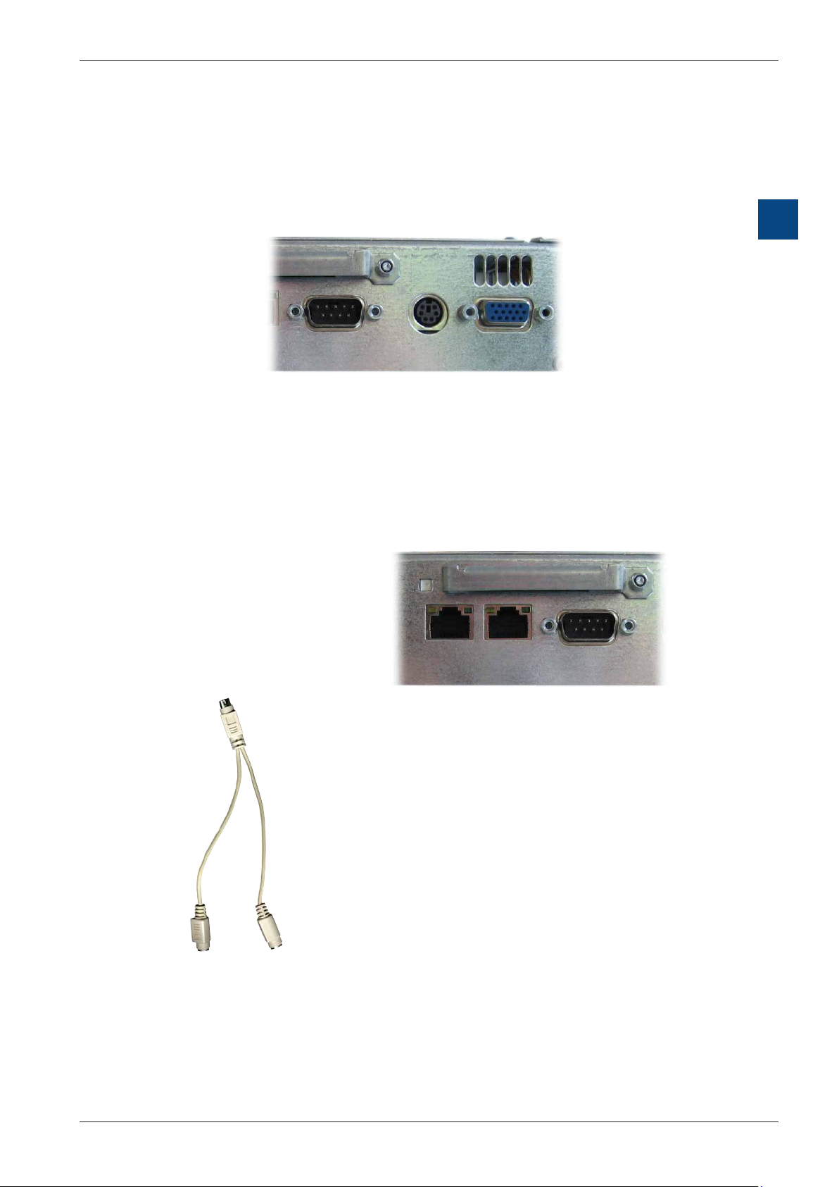
2.3 Interfaces ....................................................................................................... 2-3
2.3.1 Compact Flash slot ........................................................................................ 2-3
2.3.2 VGA/COM1/PS/2 interface ............................................................................. 2-3
2.3.3 Ethernet, USB ................................................................................................. 2-4
2.4 Back ................................................................................................................ 2-4
3 Commissioning
3.1 Power supply .................................................................................................. 3-1
3.2 Earthing concept ............................................................................................. 3-2
3.3 Flush mounting ............................................................................................... 3-2
3.4 Switch-on ........................................................................................................ 3-2
4 Basicsettingsandrststeps
5 Technical data
5.1 Physical dimensions ....................................................................................... 5-1
5.1.1 PCD7.D6100TLxxx exterior/ush mounting dimensions................................. 5-2
5.1.2 PCD7.D6100TLxxx unit dimensions ............................................................... 5-3
5.1.3 PCD7.D6120TLxxx exterior/ush mounting dimensions................................. 5-4
5.1.4 PCD7.D6120TLxxx dimensions: .................................................................... 5-5
5.1.5 PCD7.D6150TLxxx exterior/ush mounting dimensions................................. 5-6
5.1.6 PCD7.D6150TLxxx unit dimensions: ............................................................. 5-7
5.2 Electrical data ................................................................................................. 5-8
5.3 Environmental conditions ............................................................................... 5-8
6 Maintenance and support
6.1 Battery changing ............................................................................................. 6-1
6.2 Replacing background lighting........................................................................ 6-1
6.3 Cleaning.......................................................................................................... 6-2
6.4 Usage instructions for touch screens.............................................................. 6-2
A Annex
A.1 Icons ............................................................................................................... A-1
A.2 Address of Saia-Burgess ................................................................................ A-2

Manual for the PCD7.D61x0TL series│Document 26/ 865│Version pEN1│2009-06-11
Saia-Burgess Controls AG
Contents
0-2
0

Manual for the PCD7.D61x0TL series│Document 26/ 865│Version pEN1│2009-06-11
Saia-Burgess Controls AG
Contents
0-3
0
0.1 Document History
Version Published Changed Remarks
pEN1 2009-06-11 Initial version
0.2 Trademarks
Saia®is a registered trademark of Saia-Burgess Controls AG.
Microsoft, Windows 2000, Windows XP, Windows CE and the Windows logo are
either registered trademarks or trademarks of Microsoft Corporation in the USA
and/or other countries.
Technical changes are subject to the state of technology
Saia-Burgess Controls AG, 2009. © All rights reserved.
Published in Switzerland

Manual for the PCD7.D61x0TL series│Document 26/ 865│Version pEN1│2009-06-11
Saia-Burgess Controls AG
Introduction
1-1
1
1 Introduction
The PCD7.D61x0 series is suitable for visualising process data of low to medium
complexity. The process architecture used (AMD Geode LX800) gives the units
a lower power leakage and higher operating temperature range than earlier x86
systems, combined with lower equipment costs.
The devices have been developed for use with the Windows xXP open operating
system. The 2 USB ports can be used to connect external keyboards, mice, USB
sticks or certain models of printer. The integrated Ethernet interface allows the units
to be simply incorporated into existing computer networks or used as web panels.
In conjunction with the (optional) Saia®S-Web Editor visualisation software, the
devices can be used to visualise SPS data from PCD Classic and PCD xx7 series
controls.
The series comprises the PCD7.D6100TL010, PCD7.D6120TL010 and
PCD7.D6150TL010 models.
User side
Colour TFT display with resistive touch
(PCD7.D6100TL010, PCD7.D6120TL010 and PCD7.D6150TL010)
Slot side

Manual for the PCD7.D61x0TL series│Document 26/ 865│Version pEN1│2009-06-11
Saia-Burgess Controls AG
Product description
2-1
2
2 Product description
The PCD7.D61xxTL series comprises compact, mechanically robust, fanless
industrial PCs. This embedded PC system is supplied both as a box and in
combination with high-contrast industrial colour TFT displays. Screen sizes of
10.4“, 12“ and 15“ are available. The analogue resistive touchscreen is the basis
for man-machine communication. The combination of a standardised CPU unit and
different front units enables it to be perfectly matched to your requirements. Its small
dimensions are a further advantage.
The use of special procesors dispnses with the need for sensitive fan systems.
Hard disks are replaced with Compact Flash cards, so the breakdown rate is very
low, in spite of the often harsh industrial environment.
The PCD7.D61xxTL series web panels are available with the Windows®eXP
operating system, allowing you to visualise and control your equipment in a robust
and reliable way.
CPU Unit CPU: On Board AMD Geode™ LX 800/700 (533 MHz) CPU
System memory: 200-pin DDR SDRAM 256 MB
Chipset: AMD LX series + CS5536
I/O chipset: IT8712/FKX + IT8888G
BIOS: Award 512 KB FLASH ROM
Battery: CR 2032 lithium battery
SSD: External type II Compact Flash™
Display chipset: AMD LX series + TI SN75LVDS83
Interfaces Serial: 1× RS 232
Ethernet: 2× Realtek RTL8139DL,
10/100Base-TX RJ45 connector
USB: 2× USB2.0
Memory card (ext.): Type II Compact Flash
Mouse and keyboard: Via mini DIN PS/2 Y cable

Manual for the PCD7.D61x0TL series│Document 26/ 865│Version pEN1│2009-06-11
Saia-Burgess Controls AG
User side; Slot side
Product description
2-2
2
2.1 User side
Colour resistive touch TFT display - 10.4“, 12“ or 15“
2.2 Slot side

Manual for the PCD7.D61x0TL series│Document 26/ 865│Version pEN1│2009-06-11
Saia-Burgess Controls AG
Interfaces
Product description
2-3
2
2.3 Interfaces
2.3.1 Compact Flash slot
The PCD7.D61xxTL series web panels units are tted with a CFA standard (type 1)
Compact Flash slot as standard.
Position of
Compact Flash
slot
Captive screw
Note:
Only Compact Flash cards from SANDISK may be used in conjuction with the web
panel.
The Compact Flash card should only be changed with the device switched off.
2.3.2 VGA/COM1/PS/2 interface
VGA port
COM 1
PS/2 mouse/
keyboard
PS2 adapter cable for
mouse and keyboard
On all standard PCD7.D61xxTL web panels, the debug port
is supplied as a serial interface.
This interface can be congured as a debug port to support
program development.
Note:
COM 1 is only available when it has been software-enabled.
The serial port is congured to the PC XT/AT standard.
Note:
The PS/2 mouse and keyboard may only be plugged or
removed with the unit switched off.
Otherwise these input devices will not be recognised by the
operating system.

Manual for the PCD7.D61x0TL series│Document 26/ 865│Version pEN1│2009-06-11
Saia-Burgess Controls AG
Back
Product description
2-4
2
2.3.3 Ethernet, USB
Ethernet 1 (RJ45)
Ethernet 2 (RJ45)
USB 1/2
2.4 Back

Manual for the PCD7.D61x0TL series│Document 26/ 865│Version pEN1│2009-06-11
Saia-Burgess Controls AG
Power supply
Commissioning
3-1
3
3 Commissioning
3.1 Power supply
The PCD7.D61xxTL devices must only be run on functional extra-low voltage
with secure insulation in accordance with EN60950. The control transformer must
comply with EN60742.
The supply voltage must be checked against the type plate.
When wiring the power supply andthe connector, the details on the type plate must
be observed.
Before commissioning the system, all cable connections should be checked.
The 0V power supply has a low-resistance connection to the casing (earth).
24 V 0 V
24V power supply
Earth screw
The power supply is connected via a two-pole plug connector
(Phoenix MST BT 2.5/2-STF-5.08).
Supply layout
230
VAC
230 VAC
0 V
24 V DC
+ 24 V

Manual for the PCD7.D61x0TL series│Document 26/ 865│Version pEN1│2009-06-11
Saia-Burgess Controls AG
Earthing concept / Flush mounting / Switch-on
Commissioning
3-2
3
3.2 Earthing concept
To ensure that electrical faults are dealt with safely, the following points should be
observed:
● Connect device and switching cabinet by the shortest route to a central earthing
point.
● Ensure lowest impedance possible in connection between device and switching
cabinet.
● All data cables connected to the device should use shielded lines.
● The shields should be earthed at both ends. There must be a low-resistance
connection between the linked systems. High equalising currents across the shield
resulting from potential differences must be avoided.
● Earth connection to use green/yellow cable with min. 4 mm² cross-section.
3.3 Flush mounting
The device should be installed in an RF shielded housing or a metal switching
cabinet.
Adequate ventilation must be provided. To ensure that the heat generated in the
device can be dissipated, a 100 mm space must be kept clear around the unit.
The device is secured with eight hexagonal nuts.
The unit must be disconnected from the power supply for installation and de-installation.
Only the assembly components supplied should be used to mount the unit in the housing.
IP65 protection to the front can only be guaranteed if the seal is correctly positioned on the
front plate.
When installed, a 100 mm space must be kept clear to allow air to circulate around the unit.
The type and number of assembly components is dependent on the device (see Technical
Details).
The use of Compact Flash cards from different manufacturers may cause faults.
Where an internal and an external Compact Flash card are used, they must be from the
same manufacturer (same type and same size).
Failure to observe the above instructions could cause damage to the device.
3.4 Switch-on
Start-up: The PCD7.D61xxTL units boot up and load the operating system indepen-
dently.

Manual for the PCD7.D61x0TL series│Document 26/ 865│Version pEN1│2009-06-11
Saia-Burgess Controls AG
Taskbar
Basicsettingsandrststeps
4-1
4
4 Basicsettingsandrststeps
This section is still being written and will be published with the next release.

Manual for the PCD7.D61x0TL series│Document 26/ 865│Version pEN1│2009-06-11
Saia-Burgess Controls AG
Physical dimensions
Technical data
5-1
5
5 Technical data
5.1 Physical dimensions
Clearance To ensure that the heat generated in the device can be dissipated, a
50 mm space must be kept clear around the unit.

Manual for the PCD7.D61x0TL series│Document 26/ 865│Version pEN1│2009-06-11
Saia-Burgess Controls AG
Physical dimensions
Technical data
5-2
5
5.1.1 PCD7.D6100TLxxxexterior/ushmountingdimensions
Front plate: Width 318 mm
Height 244 mm
Aperture size: Width 303 mm
Height 228 mm
Depth: 77 mm
Weight: approx. 2.8 kg
Type of xing: 6 aluminium or plastic brackets with M5×30 grubscrews; DIN
914, with head and hexagonal recess, zinc-plated.
303.0 ±1.0
229.0 ±1.0
244
318
Displayfenster
Durchbruch
für
den Einbau
Fronttafeldurchbruch für den Einbau
Frontplatte, Blick auf die Gerätefrontseite
Frontplattenmaße B x H
318,0mm x 244,0mm; Tol. ±0,2mm
303,0mm x 229,0mm; Tol. ±1,0mm
Durchbruch B x H

Manual for the PCD7.D61x0TL series│Document 26/ 865│Version pEN1│2009-06-11
Saia-Burgess Controls AG
Physical dimensions
Technical data
5-3
5
5.1.2 PCD7.D6100TLxxx unit dimensions
244
318 R5
8.5
94.5
214.5
235.5
23
67
6
193
301
23.5
8.5
120
227
Seitenansicht
Blick auf die Geräteoberseite
Blick auf die Geräteunterseite
Blick auf die Geräterückseite Seitenansicht

Manual for the PCD7.D61x0TL series│Document 26/ 865│Version pEN1│2009-06-11
Saia-Burgess Controls AG
Physical dimensions
Technical data
5-4
5
5.1.3 PCD7.D6120TLxxxexterior/ushmountingdimensions
Front plate: Width 364 mm
Height 296 mm
Aperture size: Width 345 mm
Height 277 mm
Depth: 77 mm
Weight: approx. 2.8 kg
Type of xing: 8 M4 threaded bolts recessed into the front plate.
Surround thickness max. 5.0 mm
296.0
8x Bohrung 4.5
364.0
354.0
255.5
277.0 ±0.5
345.0 ±0.5
286.0
207.5
78.5
4.5
4.5
98.5
R5
Fronttafeldurchbruch für den Einbau
Blick auf die Gerätefrontseite
Durchbruch B x H
345,0mm x 277,0mm
Tol. ±0,5mm
364,0mm x 296,0mm
Tol. ±0,2mm
Frontplattenmaße B x H
Durchbruch
für
den Einbau
Displayfenster

Manual for the PCD7.D61x0TL series│Document 26/ 865│Version pEN1│2009-06-11
Saia-Burgess Controls AG
Physical dimensions
Technical data
5-5
5
5.1.4 PCD7.D6120TLxxx dimensions:
Blick auf die Geräteoberseite
Blick auf die GeräterückseiteSeitenansicht rechts
Blick auf die Geräteunterseite
Seitenansicht links
EPC/Z308/A
296
364
342
11
144
264
285
23.5 193
23
67
120
11
R5
6
274

Manual for the PCD7.D61x0TL series│Document 26/ 865│Version pEN1│2009-06-11
Saia-Burgess Controls AG
Physical dimensions
Technical data
5-6
5
5.1.5 PCD7.D6150TLxxxexterior/ushmountingdimensions
Front plate: Width 452 mm
Height 334 mm
Aperture size: Width 429 mm
Height 334 mm
Depth: 86 mm
Weight: approx. ... kg
Type of xing: 6 aluminium or plastic brackets with M5×30 grubscrews; DIN
914, with head and hexagonal recess, zinc-plated.
Fronttafeldurchbruch für
den Einbau
Durchbruch B x H =
429,0mm x 334,0mm
Tol. +1mm,
Freiraum für die Halteklötze
rundrum = 15mm, somit
Freiraum =
459,0mm x 364,0mm.
Blick auf die Gerätefrontseite
Frontplattenmaße B x H
452,0mm x 357,0mm
Tol. ±0,2mm
Durchbruch für
den Einbau
334 +1
-0
429 +1
-0
452
357
R5

Manual for the PCD7.D61x0TL series│Document 26/ 865│Version pEN1│2009-06-11
Saia-Burgess Controls AG
Physical dimensions
Technical data
5-7
5
5.1.6 PCD7.D6150TLxxx unit dimensions:
Blick auf die Geräteoberseite
Blick auf die GeräterückseiteSeitenansicht rechts
Blick auf die Geräteunterseite
Seitenansicht links
EPC/Z308/A
296
364
342
11
144
264
285
23.5 193
23
67
120
11
R5
6
274

Manual for the PCD7.D61x0TL series│Document 26/ 865│Version pEN1│2009-06-11
Saia-Burgess Controls AG
Electrical data / Environmental conditions
Technical data
5-8
5
5.2 Electrical data
Model PCD7.D6100TLxxx PCD7.D6120TLxxx PCD7.D6150TLxxx
Power supply
Operating voltage 24 V ± 20%, reverse voltage protected
Current consumption approx. 0.90 A approx. 1.10 A approx. 1.5 A
Fuse 2.5 A slow-blow
Jumper time 1 ms at 19.2 V (Ub-20%)
Display unit
Display size (inches) 10.4 12 15
Max. brightness (cd/m²) 350 300 300
Resolution (pixels) 800 × 600 800 × 600 1024 × 768
Touchscreen resistive
Processor type Onboard AMD Geode LX 800/700(533 MHz) CPU
Working memory 200-pin DDR SDRAM
512 MB
Chipset AMD LX series + CS5536
I/O chipset IT8712/FKX + IT8888G
BIOS Award 512 KB FLASH ROM
Battery CR 2032 lithium battery
SSD Internal type II Compact Flash™
Display chipset AMD LX series + TI SN75LVDS83
Interfaces
Serial 1 RS232
Ethernet 2× Realtek RTL8139DL,
10/100Base-TX RJ45 connector
USB 2× USB2.0
Memory card (external) Type II Compact Flash
Mouse and keyboard Via mini DIN PS/2 Y cable
5.3 Environmental conditions
Ambient temperature
Operation 0 ... 50° C
Storage -20 ... 60° C
Humidity acc. to DIN EN60068-2-3
Operation 10 ... 75%, non-condensing
Storage 10 ... 95%, non-condensing
Vibration in operation
acc. to DIN EN60068-2-6
Sinus
Shock
Prolonged shock
Free fall
2 g, 10 ... Hz
15 g, 11 ms
10 g, 16 ms
from 1 m (in packaging), 1× per axis
Protection type acc. to DIN
EN60529
Front
Back
IP 65
IP 20
EMV/CE Resistance to
interference
Noise emission
EN 61000-6-2
EN 61000-6-4
This manual suits for next models
6
Table of contents
Other Saia Burgess Controls Touch Panel manuals