15
17
16
18
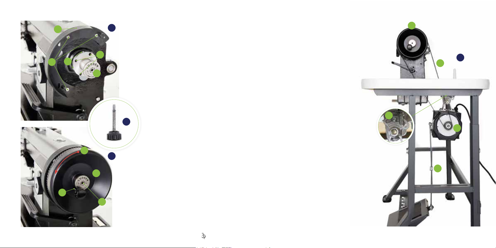
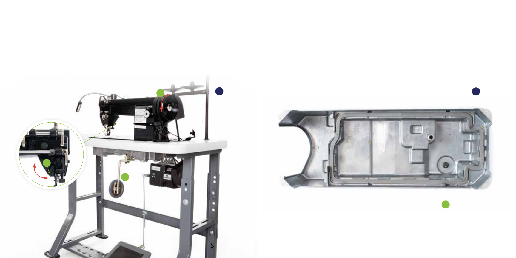
Securing the Stitch PRO
Balance Wheel
Remove the three screws (A) for the belt cover
installation. Position the C-shaped belt guard
(B) and reinstall the screws, making sure
washers are positioned as shims behind the
guard to keep it from being bent out of shape.
Unscrew the reverse-threaded Posi-Pin®nut
(C). Slide the Stitch PRO Balance Wheel (D)
onto the bushing, making sure it does not
interfere with the belt guard. If the wheel
hits the guard, reposition the washers
placed under the C-shaped belt guard
or move the bushing out further by
loosening the set screws in the bushing
ange (E).
Push the Posi-Pin®(16) through the
hole in the balance wheel (F). While
maintaining pressure on the Posi-Pin,
rotate the balance wheel (G) until the
Posi-Pin locks into one of the balance wheel
bushing holes (H). Rotation of the balance
wheel will now cause the machine to function.
To disengage the machine (for bobbin winding),
pull the Posi-Pin out of the balance wheel. The
balance wheel will now rotate without operating
the machine. Push the Posi-Pin into the hole at
the center of the Posi-Pin nut (I) to store.
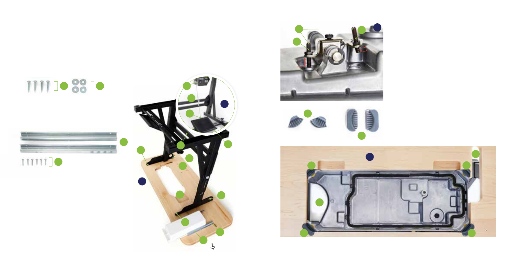
Belt Adjustment for the
Workhorse®Servo Motor
Before installing the drive belt (J), loosen the
screw (K) to allow the Workhorse Servo Motor to
freely pivot.
With the machine tilted back, slip the drive belt
over the balance wheel track (L) and guide it
onto the motor pulley (M) then carefully lower
the machine.
Pivot the motor back to tighten the belt. Proper
adjustment of the belt results in 3/8 inch of slack
when pressed by nger at its center. Retighten
set screw (K). The Linkage Bar (N) may also
need to be readjusted.
Once installed, the belt should not touch the
table and should be centered on the track of
both the balance wheel and motor pulley. Adjust
the positioning of the motor left or right by
loosening the bolts attaching the motor to the
table.
Once the motor is in the correct position and all
bolts are tightened, tilt the machine back and
remove the belt so the pulley bracket can be
installed.
Before Continuing: See “Installing the Pulley
Cover” in the Workhorse instructions.
A
H
C
G
D
I
F
N
M
K
J
L
B
E
7 | Sailrite.com Fabricator®Assembly Instructions | 8
Standard Fabricator®Assembly Standard Fabricator®Assembly