Salcom 12-34-0000 User manual

Copyright © 2017 Sea Air and Land Communications Ltd. All rights reserved.
12-34-0000
Relay Output Expansion Module
PRODUCT MANUAL
Version 1.02
April 2018

P a g e | 1
12-34-0000 RELAY OUTPUT EXPANSION MODULE
Product Manual
Sea Air and land Communications Ltd, 10 Vanadium Place, Addington, Christchurch 8024, New Zealand April 2018
Salcom Product Documentation
This document is designed to familiarise you with Salcom products and guide you through the
hardware, configuration, installation and overall system management.
Salcom is an environmentally conscious company and in an effort to conserve paper no longer
prints manuals with shipped products. All relevant documentation can be downloaded in PDF
form from our website www.salcom.com

P a g e | 2
12-34-0000 RELAY OUTPUT EXPANSION MODULE
Product Manual
Sea Air and land Communications Ltd, 10 Vanadium Place, Addington, Christchurch 8024, New Zealand April 2018
Warranty and Disclaimer
Salcom products are warranted for a period of 12 months from the date of purchase against
faulty materials and workmanship. Should any fault occur the unit should be returned to the
vendor, freight pre-paid. Please include a description of the fault to assist with prompt return.
Any unauthorised alterations or repairs will invalidate the warranty.
All information provided in this document is carefully prepared and offered in good faith as a
guide in the installation, use and servicing of Salcom products. Installers must ensure that the
final installation operates satisfactorily within the relevant regulatory requirements. Salcom
accept no responsibility for incorrect installation. We reserve the right to change products,
specifications and installation data at any time without notice

P a g e | 3
12-34-0000 RELAY OUTPUT EXPANSION MODULE
Product Manual
Sea Air and land Communications Ltd, 10 Vanadium Place, Addington, Christchurch 8024, New Zealand April 2018
Product Overview
The 12-34 is a low cost scalable relay output solution. Each 12-34 can allow 4 relays to be
controlled using the Salcom relay control protocol. The 12-34 can be daisy chained to allow
any number of relays to be controlled.
A green and red LED display operational status, a chart displaying status codes can be found
in section 4 - Connections. A 12-terminal connector is used to bring all connections from the 4
relays out. The relays are not mains rated.
Programming software is not required for this product. On startup, the firmware version number,
monoshot timer settings and unit ID are displayed, and can be changed.
The relay unit connects directly to a 12-84 receiver or PC serial port without any special
configuration requirements. The 12-84 can be configured to send all relay control packets
down the serial port to all other units.

P a g e | 4
12-34-0000 RELAY OUTPUT EXPANSION MODULE
Product Manual
Sea Air and land Communications Ltd, 10 Vanadium Place, Addington, Christchurch 8024, New Zealand April 2018
Installation and Connections
The power supply is connected via the green power connector to +13.8 Volts and Ground. The
supply input is protected against reversed connection.
Figure 1. Pin numbering: Looking into the sockets, pin 1 is on the left
S1 –Serial Port One
S2 - Serial Port Two
Pin
Description
Pin
Description
1
Ground
1
Ground
2
Not Used
2
Not Used
3
Not Used
3
Not Used
4
Not Used
4
Not Used
5
RS232 Rx
5
RS232 Tx
6
RS232 Tx
6
RS232 Rx
Figure 2. Pin outputs for relay connectors.

P a g e | 5
12-34-0000 RELAY OUTPUT EXPANSION MODULE
Product Manual
Sea Air and land Communications Ltd, 10 Vanadium Place, Addington, Christchurch 8024, New Zealand April 2018
Configuration
Figure 3. Connecting a 12-34 to a PC for configuration
The 12-34 does not require the use of configuration software, it can be set from a terminal
(9600,N,8,1). Configurable items are:
•Monoshot time for each relay
•Unit ID
On startup the 12-34 will respond with
“SALCOM 12-34-0000 Unit ID:XX”
“Relay 1 Monoshot time: 0 (Latched)”
“Relay 2 Monoshot time: 0 (Latched)”
“Relay 3 Monoshot time: 0 (Latched)”
“Relay 4 Monoshot time: 0 (Latched)”
“Enter ### to configure”
When in configuration Mode the 12-34 will respond with:
“SALCOM 12-34-0000 Configuration”
“(1) To set Relay 1 monoshot time”

P a g e | 6
12-34-0000 RELAY OUTPUT EXPANSION MODULE
Product Manual
Sea Air and land Communications Ltd, 10 Vanadium Place, Addington, Christchurch 8024, New Zealand April 2018
“(2) To set Relay 2 monoshot time”
“(3) To set Relay 3 monoshot time”
“(4) To set Relay 4 monoshot time”
“(5) To set unit ID”
When setting relay times the 12-34 will respond with:
“Relay 1: Enter time in mS (0 = Latched, Max 1800000)”
When setting unit ID the 12-34 will respond with:
“Unit ID: Enter unit ID (0-99)”

P a g e | 7
12-34-0000 RELAY OUTPUT EXPANSION MODULE
Product Manual
Sea Air and land Communications Ltd, 10 Vanadium Place, Addington, Christchurch 8024, New Zealand April 2018
Operation
After startup the unit parameters are displayed, and unit is able to be configured.
Configuration mode can only be entered within 20 seconds of startup, or within 20 seconds of
the last configuration item change. This is to prevent accidental configuration changes.
Reception of a relay control packet within the startup period will result in the 12-34 immediately
exiting config mode.
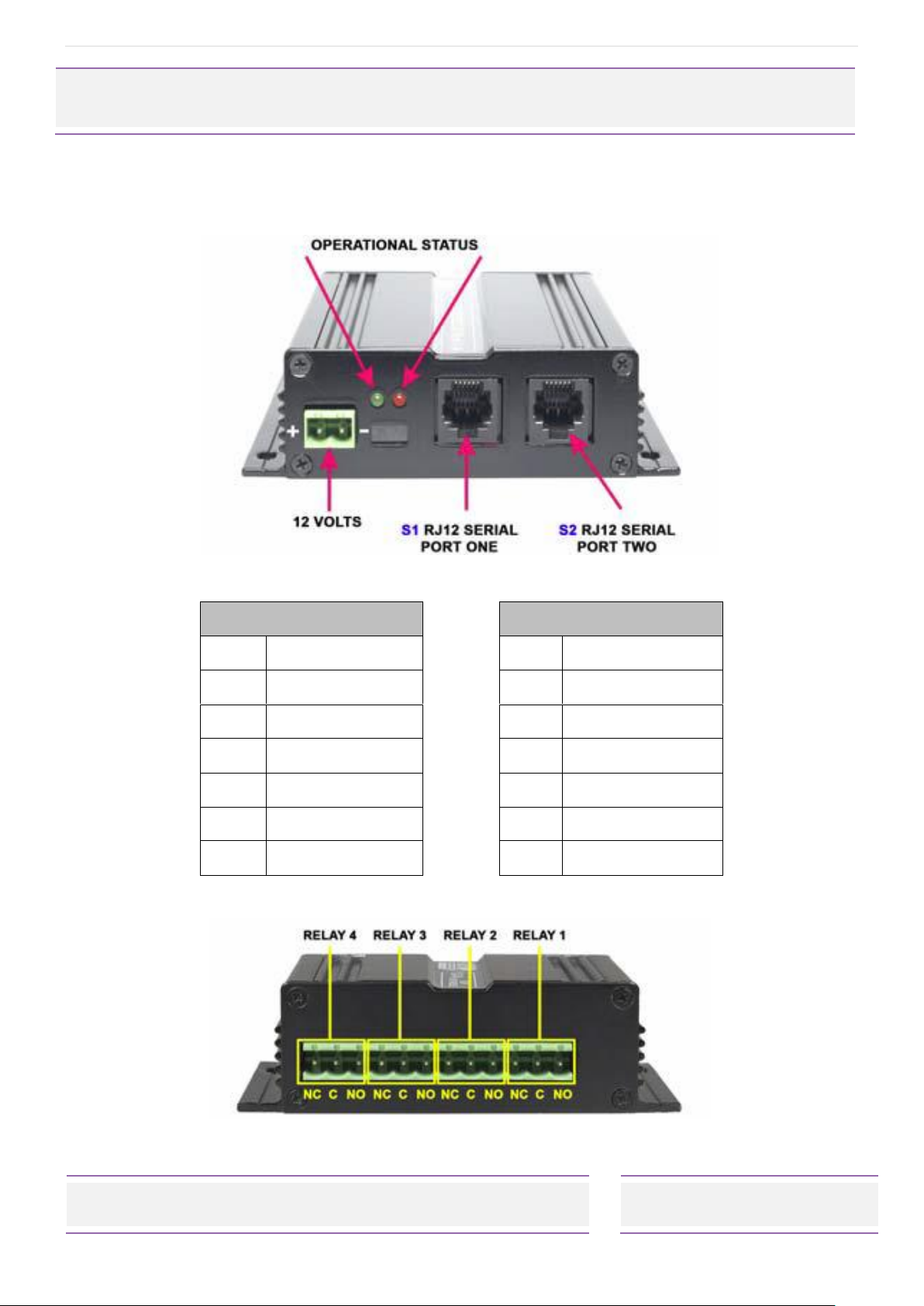
The green LED shows unit operational status –flashes when ready and idle. The red LED flashes
upon error, or is held steady on for at least one second upon reception of any command valid
for that unit.
The green LED is also held steady on for at least one second when there is a valid command for
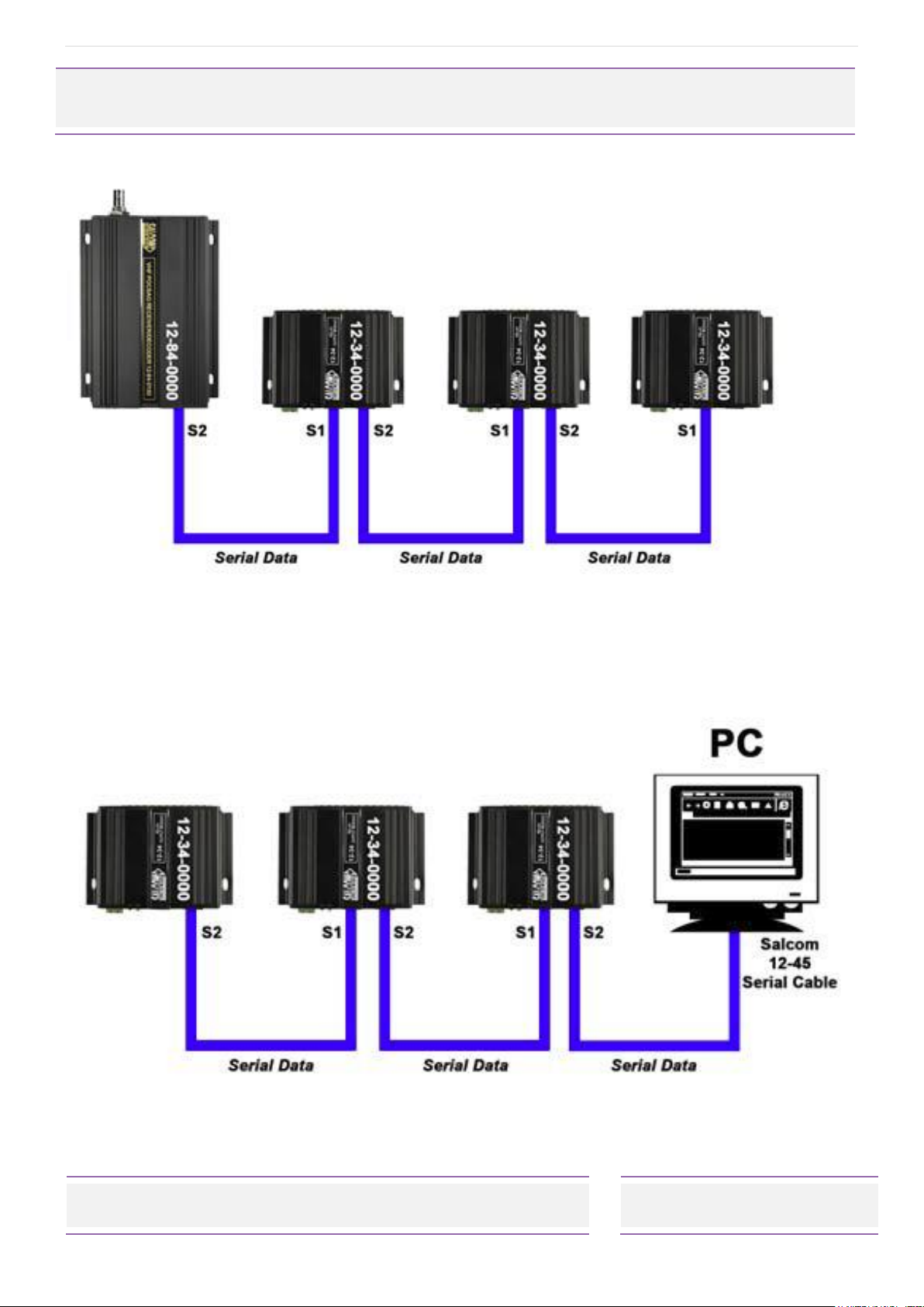
ANY unit, allowing a daisy-chained arrangement to be easily inspected.
Green LED
Red LED
Description
Slow Flashing
OFF
Unit Operational and Idle
ON (at least one second)
OFF
Valid command received, but
wrong ID
ON (at least one second)
Valid command received for this
unit
Slow Flashing
Fast Flashing
Error Condition
Relay Operation
Relays are controlled using Salcom relay control protocol –see (Relay Control Protocol below).
The 12-34 will tolerate 12-84 protocol, looking for the relay control protocol payload embedded
in the string. The 12-34 will tolerate the relay control protocol being embedded anywhere within
a string, so will cope with messages like “Main Door Open 01109” or “02112378987 01109”.
In the case of complex numeric messages the 12-34 will act on the first instance where a valid
relay control protocol is matched for that unit ID. Commands are not buffered within the 12-34,
simply inspecting the contents of the serial string, and passing the message immediately on
again to be processed again by the next 12-34 in the system.
Relay Control Protocol
Relay commands take the form IIC0X9 where:
II is the 2 character unit ID, C is a variable number of relays to close (up to 4). 0 marks the end of
relays to open, X is a variable length list of relays to close (up to 4). Commands are always
terminated by a 9. A red LED will display on the PCB showing which relay is closed.

P a g e | 8
12-34-0000 RELAY OUTPUT EXPANSION MODULE
Product Manual
Sea Air and land Communications Ltd, 10 Vanadium Place, Addington, Christchurch 8024, New Zealand April 2018
e.g.
23109 Will only address a unit with matching ID 23.
Relay 1 will be closed. No other action taken.
231209 Will close relay 1 and 2 on a unit with the ID of 23.
230129 Will open relay 1 and 2 on a unit with the ID of 23.
23012349 Will open relay 1,2,3 & 4 on a unit with the ID of 23

P a g e | 9
12-34-0000 RELAY OUTPUT EXPANSION MODULE
Product Manual
Sea Air and land Communications Ltd, 10 Vanadium Place, Addington, Christchurch 8024, New Zealand April 2018
Multiple Unit Set-Up
Figure. 4. Multiple units controlled by a 12-84 receiver
Figure. 5. Multiple units controlled by a PC

P a g e | 10
12-34-0000 RELAY OUTPUT EXPANSION MODULE
Product Manual
Sea Air and land Communications Ltd, 10 Vanadium Place, Addington, Christchurch 8024, New Zealand April 2018
Technical Specification
12-34-0000 - Relay Output Expansion Module
Power Supply
+13.8V typical (11 to 15 VDC range)
Power Consumption
Normal Operation: 37mA
Relays: 20mA per energized relay
Configuration Application
Terminal
Programming Cable
12-45-0000 (RJ12 - DB9)
Can be used with a USB to RS232 DB9 Serial Adapter Cable
Serial Port
9600 , N, 8, 1; RS232
Discrete Outputs
4 Relay Contacts (1A @ 24VDc)
Note: Not suitable for 240VAC Connections
Connectors
Serial Port 1 (RS232) = RJ12 (6P6C)
Serial Port 2 (RS232) = RJ12 (6P6C)
Relay Outputs (4 off) = 12-way plug & socket, screw connections
(supplied)
Power Connector
2-way plug & socket, screw connections (supplied)
Environmental Protection
Not suitable for outdoor use and should be protected from adverse
environmental conditions
Operating Temperature
-10ºC to +50ºC (+14ºF to +122ºF)
Indicators
Power LED (Green)
- Slow Flashing = Normal Operation
- Solid (>1s) = Valid Command Received
Status LED (Red)
- On = Valid Command for This Unit
- Fast Flashing = Error Condition
Weight
160g
Enclosure Dimensions
70mm x 100mm x 30mm (WxDxH)
Enclosure Material
Extruded aluminium
Colour
Matt black

P a g e | 11
12-34-0000 RELAY OUTPUT EXPANSION MODULE
Product Manual
Sea Air and land Communications Ltd, 10 Vanadium Place, Addington, Christchurch 8024, New Zealand April 2018
How to Contact Us
Sea Air and Land Communications (Salcom) Ltd
10 Vanadium Place
Addington
Christchurch 8024
New Zealand
T: +64 (0)3 379 2298
W: www.salcom.com
Table of contents
Other Salcom Control Unit manuals
Popular Control Unit manuals by other brands

CTJ
CTJ COM Express Type 6 104e user guide

Phason
Phason PEC Plus User manual and installation guide

Cameron
Cameron TK Installation, operation and maintenance manual

SMC Networks
SMC Networks S070 Series Installation and maintenance manual

ADLINK Technology
ADLINK Technology MPC-8164 user manual

SEA
SEA USER 2 24V DG ALL IN manual