manuals.online logo
Brands
  1. Home
  2. •
  3. Brands
  4. •
  5. EMS
  6. •
  7. Control Unit
  8. •
  9. EMS EC-41-0200 User manual

EMS EC-41-0200 User manual

1 Pre installation 2 Components
3
Part no Product description
EC-41-0200 EMS Wireless Zone Interface Module
Zone Interface Module
Installation Guide
IDENT REV D ATE
FC-610-001
EN300 200-2
0905 !
20K 4K7
CN/O
20K = Red/Bl
4k7= Yellow
EOLResistor
Conguration
ANTENNA
2
1
4 Remove cable entry points 5 Fix to the wall
Drill the cable entry
points as necessary.
Cable glands should
be used.
DO NOT leave excess
cable in the device.
ON
INPUT1 INPUT2
EXPAN1 EXPAN2
OUTPUT 2
OUTPUT 1
IP- IP+ IP- IP+
3VDC SET RST
N/O COM N/C
3VDC SET RST
N/O COM N/C
DO NOT use
=
Available
cable entry
points
=
3 Mounting location guidelines
Ensure the ZIM is not installed
within 2 m of the control panel
or any other wireless or
electrical equipment.
Ensure the ZIM is not installed
within 0.6 m of any metal work.
Ensure the ZIM is not installed
within 0.6 m of the WZM.
WIRELESS ZONE INTERFACEMODULE
WZM ZIM
0.6 m
Existing
control panel
WZM ZIM
0.6 m
POWER
FAU LT
WIRELESSZONE MONITOR
2 m
WIRELESSZONEINTERFACE MODULE
WIRELESSZONE INTERFACEMODULE
POWER
FAU LT
WIRELESSZONE MONITOR
Existing
control panel
FIRE
FireAlarm Control
FIRE
FireAlarm Control
!
Installation must conform to applicable local installation
codes and
should only be installed by a fully trained
competent person.
Ensure that the device is installed as per the site survey.
The use of a non-metallic spacer should be considered if
mounting the device on to a metal surface.
DO NOT press the log on button on a pre-programmed
device, as this will cause communication with the control
panel to be lost. Should this happen, delete the device from
the system and add it back on.
This device contains electronics that may be susceptible to
damage from Electrostatic Discharge (ESD). Take appropriate
precautions when handling electronic boards. 4x lid fixing screws Front lid Back box
123
For optimum wireless
performance, the
following must be
observed:
Use all four circled
fixing positions to
ensure a firm fixing.
Use suitable fasteners
and fixings.
ANTENNA
KEEP CABLES AWAY FROMTHIS AREA
LOGON
OUTPUT 2OUTPUT 1
3VDC SET RST
INPUT 1 INPUT 2
LED
ENABLE
POWER
INPUT
INPUT
FAULT
CLOSED
0 1
1
64
F-SAFE
N/O COM N/C
IP- IP+ IP- IP+
3VDC SET RST N/O COM N/C
EXPAN1 EXPAN2
RELAY ON
RELAY ON
2
4
8
16
32
ON
1 2 3 4 5 6 7 8
012ABC
Fixing position
location within
cavity
©2021 EMS Ltd. All rights reserved. Page 1 of 2 TSD142-99 Iss 6 15/12/2021 AJM
7 Power device
When fitting / replacing batteries; observe correct polarity,
using only specified batteries.
Connect the power jumper across the PIN header.
6 Connection wiring
Once powered, reassemble the device.
OUTPUT 2OUTPUT 1
3VDC
SET RST
INPUT 1 INPUT 2
LED
ENABLE
PO WER
INPUT 1
INPUT 2
FAULT
CLOSED
0 1
1
64
F-SAFE
N/O COM N/C
IP- IP+ IP- IP+
3VDC SET RST N/O COM N/C
EXPAN1 EXPAN2
RELAY ON
RELAY ON
2
4
8
16
32 device
unpowered
(pins unlinked)
device
powered
(both pins linked)
Refer to the wireless zone
monitor engineers guide
(TSD143) for full wiring
details.
Free to download from
www.emsgroup.co.uk
8 Configuration
The ZIM must be added to the WZM, before adding other wireless
devices to the system.
Refer to the wireless zone monitor engineers guide (TSD143)
for full programming details.
Free to download from
www.emsgroup.co.uk
9 LED operation
The device has six indication LEDs. Pressing the LED enable button
enables their illumination for 10 minutes before automatically
timing out.
2x input fault: YELLOW LED ON = FAULT
2x input closed: RED LED ON = ACTIVE
2x output: RED LED ON = ACTIVE
CLOSED
FAULT
INPUT 1
INPUT 2
Input 2
LEDs
Input 1
LEDs
Output 1 LED Output 2 LED
Operating
temperature -10 to +55 °C
Storage
temperature 5 to 30 °C
Humidity 0 to 95% non-condensing
Supply 6x AA alkaline (Panasonic LR6AD Powerline
/ Varta 4006 Industrial)
CAUTION!
Fitting of an incorrect battery type invalidates the product certification and
may result in poor performance.
Output rating 2A at 24 VDC
IP rating IP65
Operating frequency 868 MHz
Output transmitter
power Auto adjusting 0 to 14 dBm (0 to 25 mW)
Dimensions (W x H x D) 270 x 205 x 75 mm
Weight 0.95 kg
Location Type A: For indoor use
2012/19/EU (WEEE directive):
Products marked with this symbol cannot be
disposed of as unsorted municipal waste in the
European Union. For recycling, return this product to
your local supplier upon purchase of equivalent new
equipment, or dispose of it at designated collection
points. For more information see
www.recyclethis.info
Dispose of your batteries in an environmentally
friendly manner according to your local regulations.
European Union
directives
EMS declares that this device is in compliance with
Directive 2014/53/EU. The full text of the EU
declaration of conformity is available at the following
internet address:
www.emsgroup.co.uk
Approved to EN54-18:2005. Fire detection and fire alarm
systems. Part 18: Input/output devices.
EN54-25:2008. Incorporating corrigenda
September 2010 and March 2012. Fire detection
and fire alarm systems. Part 25: Components using
radio links.
Certification
Certification body
CPR DoP 0359-CPR-00436
Carrier Manufacturing Polska Sp. Z o.o. Ul. Kolejowa
24. 39-100 Ropczyce, Poland
Manufacturer
Year of
manufacture See devices serial number label
0905
14
Specification Regulatory Information
©2021 EMS Ltd. All rights reserved. Page 2 of 2 TSD142-99 Iss 6 15/12/2021 AJM
Other EMS Control Unit manuals

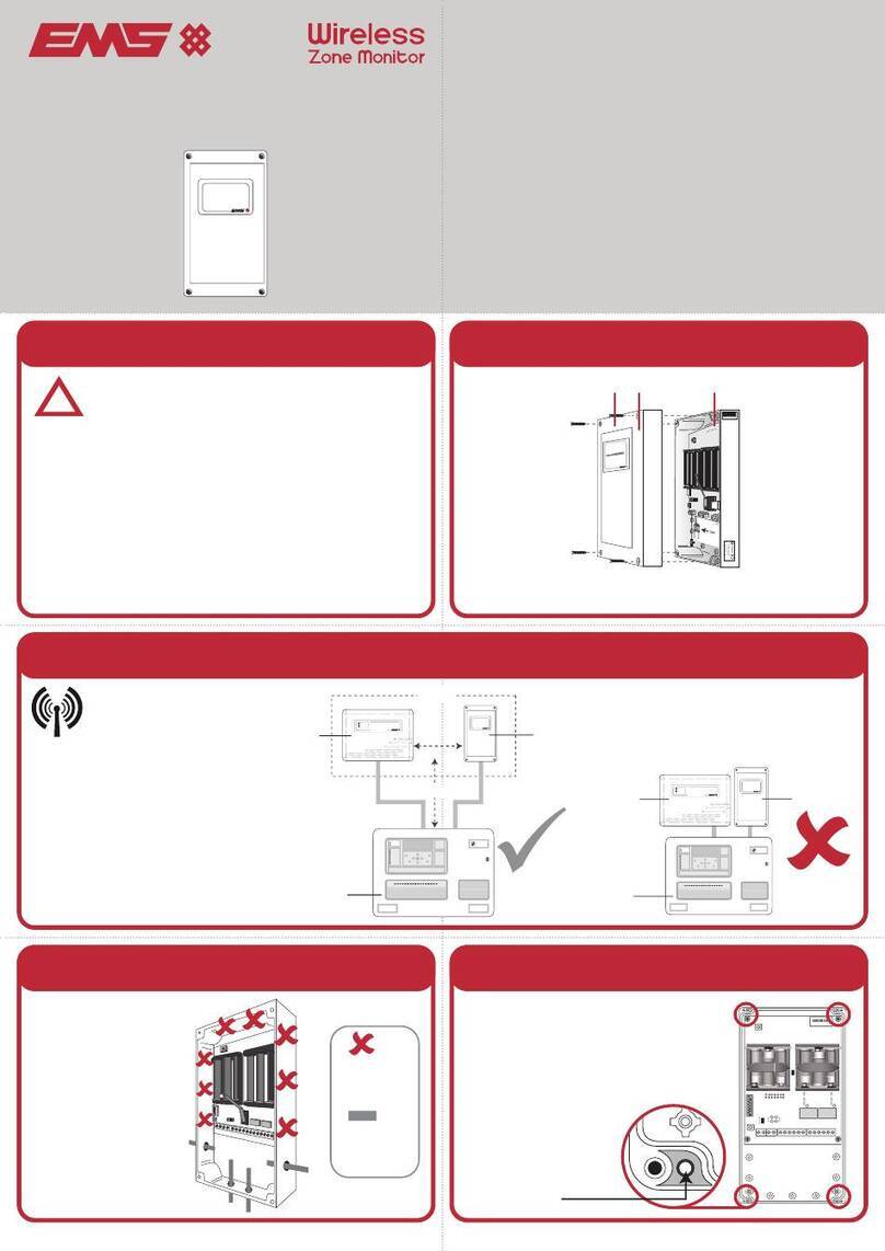
EMS EMS520 User manual

EMS

EMS EMS520 User manual

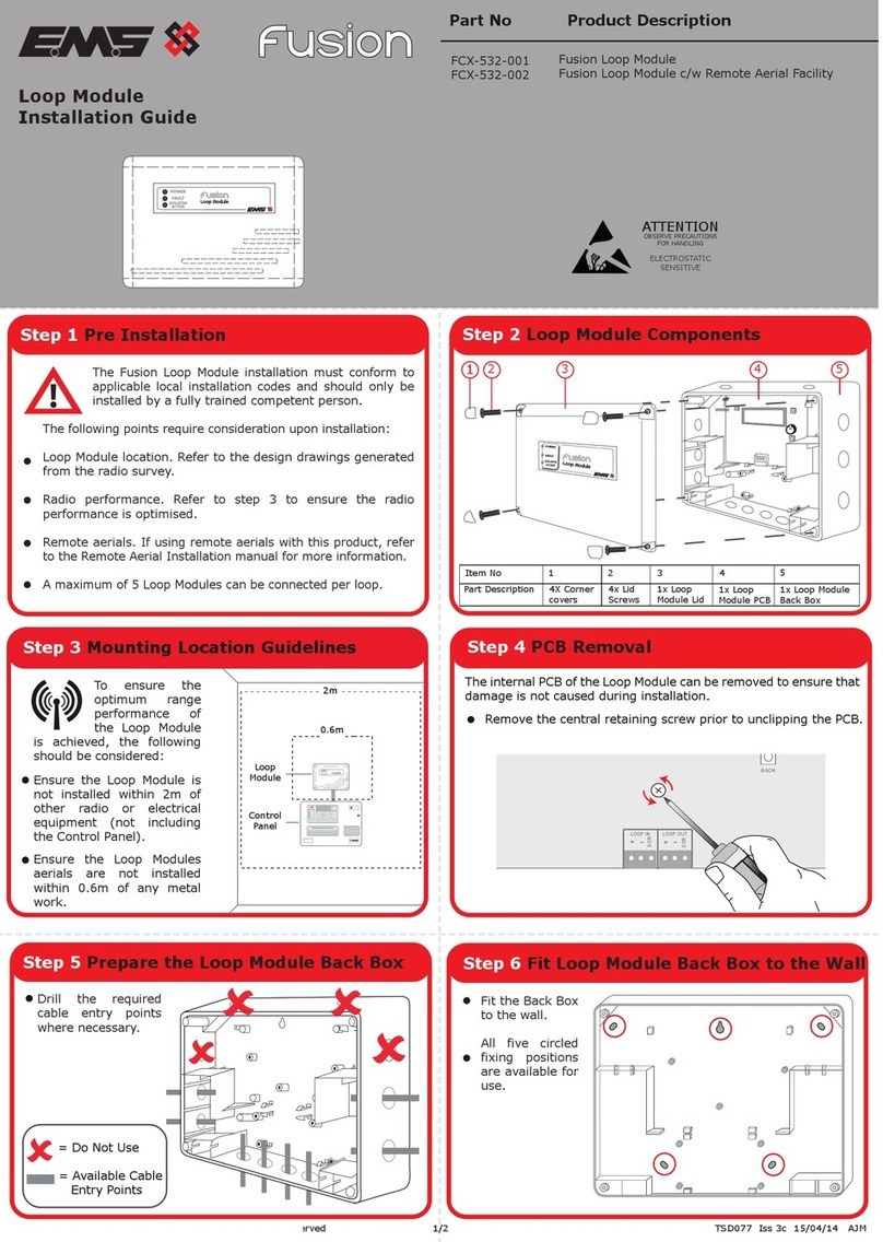
EMS fusion FCX-532-001 User manual

EMS

EMS fusion FCX-532-001 User manual

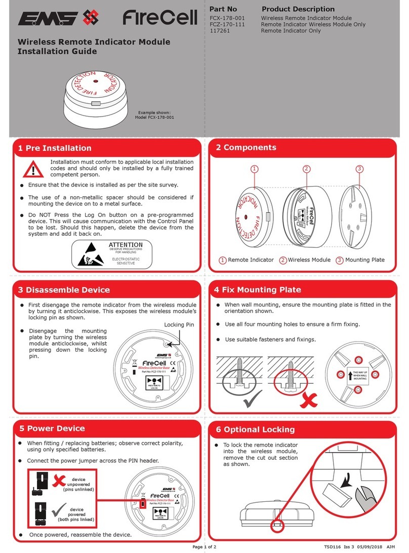
EMS FireCell FCZ-170-111 User manual

EMS

EMS FireCell FCZ-170-111 User manual

EMS LRP2000 Series User manual

EMS

EMS LRP2000 Series User manual

EMS ZITON Owner's manual

EMS

EMS ZITON Owner's manual

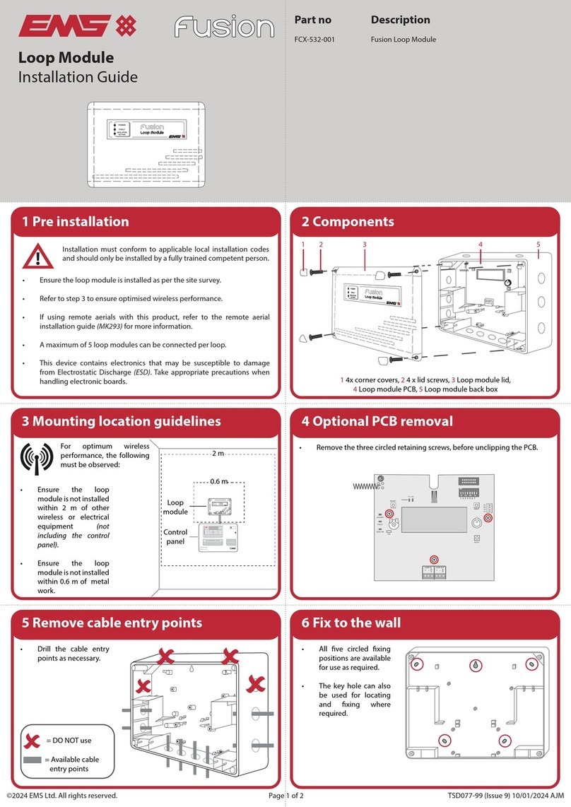
EMS Fusion FCX-532-001 User manual

EMS

EMS Fusion FCX-532-001 User manual

EMS EC-41-0200 User manual

EMS

EMS EC-41-0200 User manual

EMS FireCell FCZ-170-111 User manual

EMS

EMS FireCell FCZ-170-111 User manual

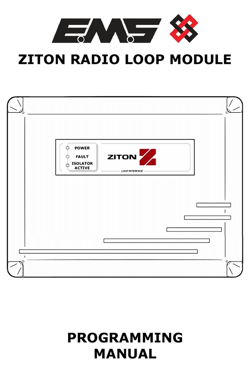
EMS ZITON RADIO LOOP MODULE Owner's manual

EMS

EMS ZITON RADIO LOOP MODULE Owner's manual

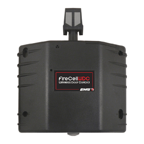
EMS FireCellWDC User manual

EMS

EMS FireCellWDC User manual

Popular Control Unit manuals by other brands

Vaisala HMM30C operating manual

Vaisala

Vaisala HMM30C operating manual

Keysight M9101A Startup guide

Keysight

Keysight M9101A Startup guide

Kuhse KEA 350 P2 user manual

Kuhse

Kuhse KEA 350 P2 user manual

PEHA 940/24 JRM Installation and operating instructions

PEHA

PEHA 940/24 JRM Installation and operating instructions

Dometic Switch200VTO Installation and operating manual

Dometic

Dometic Switch200VTO Installation and operating manual

Xycom XVME-678 manual

Xycom

Xycom XVME-678 manual

Z3 Technology Z3-DM816X-RPS RDK user guide

Z3 Technology

Z3 Technology Z3-DM816X-RPS RDK user guide

Azbil ACTIVAL VY5303A Specifications & instructions

Azbil

Azbil ACTIVAL VY5303A Specifications & instructions

TQ TQMxE39S series user manual

TQ

TQ TQMxE39S series user manual

CMO VALVES UB Series Instruction and maintenance manual

CMO VALVES

CMO VALVES UB Series Instruction and maintenance manual

Sena Parani ESD100V2 quick start guide

Sena

Sena Parani ESD100V2 quick start guide

resideo V8200 installation instructions

resideo

resideo V8200 installation instructions

ABB Baldor BC141 Installation & operating manual

ABB

ABB Baldor BC141 Installation & operating manual

gefran GFX4-ETHERNET Installation and operation manual

gefran

gefran GFX4-ETHERNET Installation and operation manual

Faulhaber PRECIstep AD CM M1S user manual

Faulhaber

Faulhaber PRECIstep AD CM M1S user manual

Siemens SIRIUS 3SB3 operating instructions

Siemens

Siemens SIRIUS 3SB3 operating instructions

Trane Tracer MP503 Installation and operation

Trane

Trane Tracer MP503 Installation and operation

nvent ERIFLEX UDJ125A manual

nvent

nvent ERIFLEX UDJ125A manual

manuals.online logo
manuals.online logoBrands
  • About & Mission
  • Contact us
  • Privacy Policy
  • Terms and Conditions

Copyright 2025 Manuals.Online. All Rights Reserved.