Salcom 12-38-0000 User manual

Copyright © 2017 Sea Air and Land Communications Ltd. All rights reserved.
12-3 -0000
VHF / UHF Transceiver
PRODUCT MANUAL
Version 1.05
February 2019

P a g e | 1
12-3 -0000 VHF AND UHF TRANSCEIVER Product Manual
Sea Air and Land Communications Ltd, 10 Vanadium Place, Addington, Christchurch 024, New Zealand February 2019
Salcom Product Documentation
This document is designed to familiarize you with Salcom products and guide you through the
hardware, configuration, installation and overall system management.
Salcom is an environmentally conscious company and in an effort to conserve paper no longer
prints manuals with shipped products. All relevant documentation can be downloaded in PDF
form from our website www.salcom.com

P a g e | 2
12-3 -0000 VHF AND UHF TRANSCEIVER Product Manual
Sea Air and Land Communications Ltd, 10 Vanadium Place, Addington, Christchurch 024, New Zealand February 2019
Warranty and Disclaimer
Salcom products are warranted for a period of 12 months from the date of purchase against
faulty materials and workmanship. Should any fault occur the unit should be returned to the
vendor, freight pre-paid. Please include a description of the fault to assist with prompt return. Any
unauthorised alterations or repairs will invalidate the warranty.
All information provided in this document is carefully prepared and offered in good faith as a
guide in the installation, use and servicing of Salcom products. Installers must ensure that the final
installation operates satisfactorily within the relevant regulatory requirements. Salcom accept no
responsibility for incorrect installation. We reserve the right to change products, specifications
and installation data at any time without notice

P a g e | 3
12-3 -0000 VHF AND UHF TRANSCEIVER Product Manual
Sea Air and Land Communications Ltd, 10 Vanadium Place, Addington, Christchurch 024, New Zealand February 2019
Product Overview
The 12-3 -0000 transceiver is capable of accurate control and telemetry over long distances.
Designed to be used in industrial environments it can withstand temperature extremes as well as
being resilient to electrical noise often found in industrial plants.
The transceiver, along with its integrated input/output interface is designed for the control and
telemetry of industrial machines with high accuracy and speed.
The 12-3 -0000 has an on-board SD card which is used to store the configuration of a unit, this
allows for ease of copying a configuration between units e.g. to replicate a system, the capturing
of log files and storage of audio wave files. The unit can be set up to respond to an event, such
as an input, by selecting a radio channel and broadcasting the audio wave file. Anyone carrying
a radio transceiver, set to that channel, can then receive the message.
The 12-3 -0000 could also be configured as a store and forward radio repeater to extend the
radio range of any installation. This will allow monitoring and control of sites in difficult locations
without clear radio access.
The 12-3 -0000 is a 5-watt analogue transceiver with POCSAG capability for both transmitting
and receiving and comes in two variants, a VHF (136-174 MHz) or UHF (440-470 MHz). All
parameters are programmable such as frequency, power output, deviation, POCSAG data
transmission.
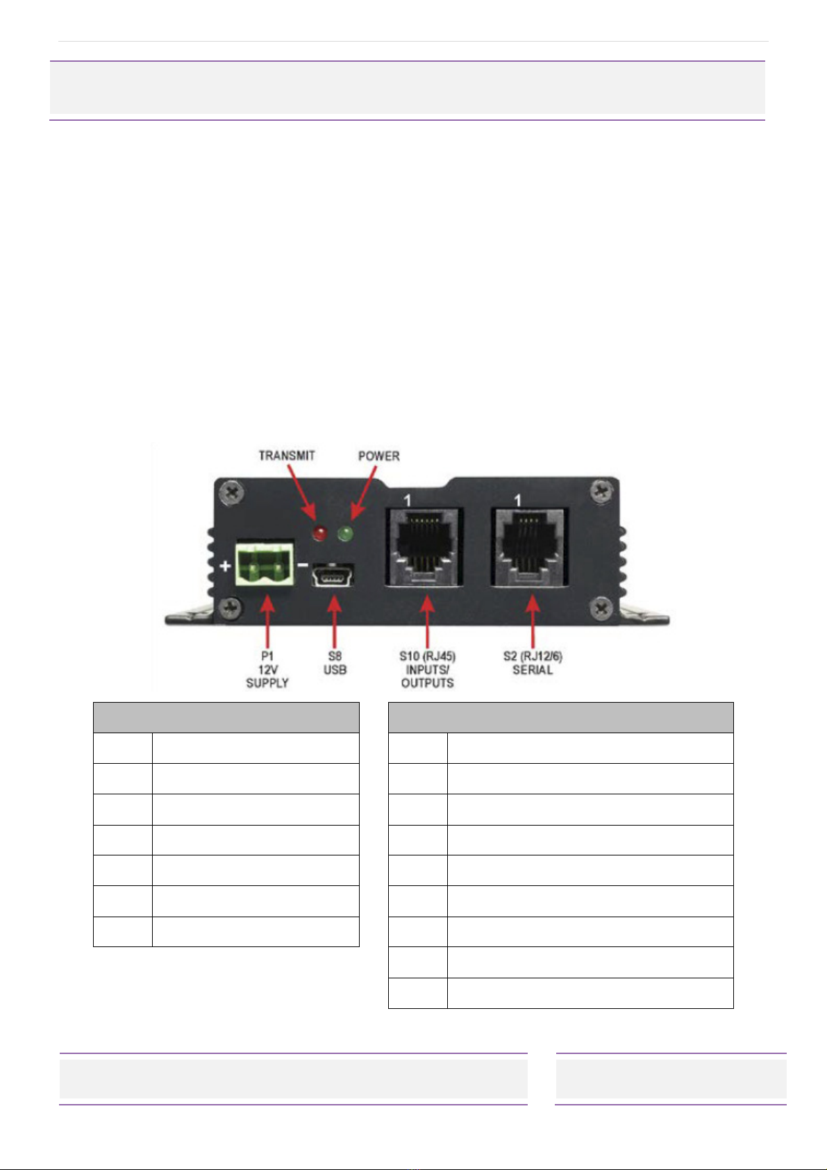
The USB port, or the RS232 serial port can be used to initiate paging transmissions using the
SALCOM propriety protocol, Paging Entry Protocol (PET) or Telocator Alphanumeric Protocol
(TAP) PG1 protocol

P a g e | 4
12-3 -0000 VHF AND UHF TRANSCEIVER Product Manual
Sea Air and Land Communications Ltd, 10 Vanadium Place, Addington, Christchurch 024, New Zealand February 2019
Installation and Connections
The power supply is connected via PI, green power connector to +13. Volts DC and Ground.
The 12-3 is protected against reversed supply connections. The power source must be
reasonably noise free.
Radiation Hazard: Important! To comply with FCC Controlled/Occupational Exposure Limits the
aerial must be positioned or mounted to operate at least 0.26 metres away from Operational
Staff and 0.57 metres away from the general public.
It is recommended to site the aerial a few metres away from the 12-3 to avoid the possibility of
RF feedback causing problems with the transmitter operation. An outside aerial is preferable and
will provide better radio coverage. The aerial connection is via the BNC connector and should
present a nominal load of 50Ω, with a VSWR of better that 1. :1.
External indicators consist of a power indicator GREEN LED, normally flashing ON once a
second to indicate healthy microcontroller operation.
S2 RJ12 S10 RJ45
Pin Descri tion Pin Descri tion
1 Ground 1 Ground
2 Output 1 2 PTT Input
3 Input 2 3 Mic / AV In
4 Input 1 4 Input 3
5 RS232 Tx 5 Output 2
6 RS232 Rx 6 Busy
7 Speaker / AV Out
+5V
Output1 and 2 are Open Collector and Inputs 1, 2 and 3 are triggered by grounding the pins.

P a g e | 5
12-3 -0000 VHF AND UHF TRANSCEIVER Product Manual
Sea Air and Land Communications Ltd, 10 Vanadium Place, Addington, Christchurch 024, New Zealand February 2019
Configuration
All serial commands are sent and received using a standard terminal application connected at
9600:N: :1 using a 12-45 programming adaptor. Ensure that the correct COM port is selected.
Sending MAP<CR> to the 12-3 will display current configuration information. To change a
parameter refer to the terminal programme instructions. An example is given below:
+03=456675000<CR> to change the RX frequency
Using the USB
If the connection is via the USB then the 12-3 will appear as a drive on the computer. The
configuration information is held in the config.ini file which can be opened and edited using a
standard text editor. Once the required parameter has been changed save the file back to the
original location.
Whilst the USB is connected the Green LED will flash faster.
Parameter Format
Each parameter follows the same format. An example is given below:
;Tx Frequency set the Transit Frequency in Hz the command description
;+20=456675000 an example for the correct format
+20=456675000 the actual parameter set

P a g e | 6
12-3 -0000 VHF AND UHF TRANSCEIVER Product Manual
Sea Air and Land Communications Ltd, 10 Vanadium Place, Addington, Christchurch 024, New Zealand February 2019
Analogue Transmissions Via External Modulation Source
Connect the External Modulation Source to Pin 3 of connector S10. This input is configured for a
fixed amplitude input source of 100mV rms, or 2 0mV p-p. Monitor the RF output on a FM
modulation on a meter and adjust the deviation to ±4kHz. Adjust the deviation by fine adjustment
of the input signal, or via the PSD by changing the DAC setting within the ‘Audio in Atten’ box.
Do not click ‘Enable Calibration’ tick box for this adjustment. It is important to ‘Read’ first, then
alter the settings, a higher number gives more deviation and lower number less deviation.
It is also important to keep the deviation to ±4kHz to avoid getting into the compression range.
Then press ‘Program’ in the ‘Configuration’ section to save the settings.

P a g e | 7
12-3 -0000 VHF AND UHF TRANSCEIVER Product Manual
Sea Air and Land Communications Ltd, 10 Vanadium Place, Addington, Christchurch 024, New Zealand February 2019
Salcom Protocol
Salcom protocol takes the basic form: PP sLsMMMMMM<CR>, where:
P is either CA (512 baud alpha), CN (512 baud numeric), ca (1200 baud alpha), or cn
(1200 baud numeric).
X is a 7 digit RIC code.
S is a space.
L is a digit (1 to 4 beep level)
M is the message payload (up to 240 characters).
<CR> is a carriage return (enter key)
CA ________________________________________________________________
Usage: CA<pager#>[<space>]<level>[<space>]<message><CR>
Description: Call alphanumeric pager
Example: CA111935 1 Please return to reception<CR>
Response: CA111935 1<CR><SPACE>Page Sent<CR><LF>
CN ________________________________________________________________
Usage: CN<pager#>[<space>]<level>[<space>]<message><CR>
Description: Call numeric pager
Example: CN111935 1 777<CR>
Response: CN111935 1<CR><SPACE>Page Sent<CR><LF>
RES ________________________________________________________________
Usage: RES<CR>
Description: Reset 12-3 microcontroller
Example: RES<CR>
Response: SALCOM 12-3 -0000 VX.XX<CR><LF>

P a g e | 8
12-3 -0000 VHF AND UHF TRANSCEIVER Product Manual
Sea Air and Land Communications Ltd, 10 Vanadium Place, Addington, Christchurch 024, New Zealand February 2019
SN? ________________________________________________________________
Usage: SN?<CR>
Description: Retrieve unit serial number and firmware revision
Example: SN?<CR>
Response: SALCOM 12-3 -0000 VX.XX 5122345<CR><LF>

P a g e | 9
12-3 -0000 VHF AND UHF TRANSCEIVER Product Manual
Sea Air and Land Communications Ltd, 10 Vanadium Place, Addington, Christchurch 024, New Zealand February 2019
Trouble Shooting
The following table may help in problem solving where necessary.
Fault Check
No illumination of Green LED Bad power supply connection
Input activated but no transmission Software configuration incorrect
Unit transmits but nothing received Poor aerial
Wrong frequency
Incorrect RIC
Incorrect baud-rate
Power too low
Unit too hot (the unit will also send out an alter via
the serial port)
Too much vibration
No RS232 serial communication Incorrect COM port connection selected Software
configuration incorrect
Cable faulty
Unit starts, but does not complete
transmission
Poor supply voltage
RF interference (the unit will also report an error on
the terminal port)

P a g e | 10
12-3 -0000 VHF AND UHF TRANSCEIVER Product Manual
Sea Air and Land Communications Ltd, 10 Vanadium Place, Addington, Christchurch 024, New Zealand February 2019
Technical S ecification
12-38-0000 – VHF / UHF Transceiver
Frequency Range 136 - 174MHz - VHF (Model No. 12-3 -0150)
440 - 470MHz - UHF (Model No. 12-3 -0450)
Frequency Selection User configurable
Power Supply +13. V typical (11 to 15 VDC range)
Power Consumption Standby: 140mA
Transmit: 1.2A @ 5W
Transmit Power 5W, 4W, 2W, 1W, 500mW, 250mW
Channel Spacing 6.25kHz, 12.5kHz, 25kHz
Modulation FSK with NRZ Data
True FM for Audio
Deviation ±2.25kHz or ±4.5kHz
Transmit Duty Cycle Up to 100%
Receiver Sensitivity -119dBm for 12 dB SINAD
Audio Modes Analogue FM transmission and reception
Audio Conditioning 300Hz to 3kHz passband software defined pre-emphasis DTMF and CTCSS
(<300Hz)
Muting Software defined muting level
Baud Rates 512, 1200
Will not operate with 1200 baud rate pagers
Message Format POCSAG
Configuration Application Salcom Configuration Tool
Programming Cable 12-45-0000 (RJ12 to DB9)
Can be used with a USB to RS232 DB9 Serial Adapter Cable
Serial Port 9600 , N, , 1; RS232
Serial Protocols Salcom
Discrete Inputs 3 (Ground activated)
Discrete Outputs 2 (Open collector)
Other I/O PTT; Busy; Mic/AV In; Mic/AV Out; +5V
Connectors Serial Port (RS232) = RJ12 (6P6C)
Serial Port / Flash Drive = mini USB
Input / Outputs = RJ45 ( C)
Power Connector 2-way plug & socket, screw connections (supplied)
RF Connector 50Ω BNC
Environmental Protection Not suitable for outdoor use and should be protected from adverse
environmental conditions
Operating Temperature -10ºC to +60ºC (+14ºF to +140ºF)
Indicators Power LED (Green)
- Slow Flashing = Normal Operation
- Rapid Flashing = USB Connected
Status LED (Red)
- On = Transmitting
- Flashing = Error Condition
Weight 31 g

P a g e | 11
12-3 -0000 VHF AND UHF TRANSCEIVER Product Manual
Sea Air and Land Communications Ltd, 10 Vanadium Place, Addington, Christchurch 024, New Zealand February 2019
Enclosure Dimensions 100mm x 130mm x 30mm (WxDxH)
Enclosure Material Extruded aluminium
Colour Matt black
Type Approvals AS/NZS 4295: 2004 (RF)
AS/NZS 4769.1:2000 + Amendment 1:2002 (RF)

P a g e | 12
12-3 -0000 VHF AND UHF TRANSCEIVER Product Manual
Sea Air and Land Communications Ltd, 10 Vanadium Place, Addington, Christchurch 024, New Zealand February 2019
How to Contact Us
Sea Air and Land Communications (Salcom) Ltd
10 Vanadium Place
Addington
Christchurch 024
New Zealand
T: +64 (0)3 379 229
W: www.salcom.com
E: sales@salcom.com
Other manuals for 12-38-0000
1
Table of contents
Other Salcom Transceiver manuals