Salcom 20-90 User manual

Copyright © 2021 Sea Air and Land Communications Ltd. All rights reserved.
20-90
VHF / UHF Low Power Transceiver with Ethernet
PRODUCT MANUAL
Version 0.1.1
September 2021

P a g e | 1
20-90 VHF & UHF TRANSCIEVER
Product Manual
Sea Air and Land Communications Ltd, 10 Vanadium Place, Addington, Christchurch 8024, New Zealand September 2021
Warranty and Disclaimer
Salcom products are warranted for a period of 12 months from the date of purchase against
faulty materials and workmanship.
If any fault should occur, the unit should be returned to the vendor, freight pre-paid. Please
include a description of the fault to assist with prompt return. Any unauthorised alterations or
repairs will invalidate the warranty.
We reserve the right to change products, specifications, and installation data at any time,
without notice.
All information provided in this document is carefully prepared and offered in good faith as a
guide in the installation and use of Salcom products. Installers must ensure that the final
installation operates satisfactorily within the relevant regulatory requirements. Salcom accepts
no responsibility for incorrect installation.
Please refer to the product specifications for specific certification information.

P a g e | 2
20-90 VHF & UHF TRANSCIEVER
Product Manual
Sea Air and Land Communications Ltd, 10 Vanadium Place, Addington, Christchurch 8024, New Zealand September 2021
Contents
Warranty and Disclaimer ................................................................................................................................1
Product Overview............................................................................................................................................4
Connectors and Indicators ............................................................................................................................6
Physical Dimensions.........................................................................................................................................7
20-90 Installation and Quick Start Guide......................................................................................................8
Salcom Message Protocol ...........................................................................................................................10
Channel Busy Detection...............................................................................................................................11
CAP codes......................................................................................................................................................12
Input and Output Operation .......................................................................................................................13
Salcom Relay Control Protocol ...................................................................................................................14
20-90 Output Map .........................................................................................................................................15
Special Functions...........................................................................................................................................16
POCSAG Rapid..............................................................................................................................................18
Watchdog messages....................................................................................................................................19
Store and Forward.........................................................................................................................................20
Serial Commands ..........................................................................................................................................21
Sacoto Configuration Tool ...........................................................................................................................22
Welcome to Sacoto!.....................................................................................................................................23
Sacoto Connection Settings ........................................................................................................................24
Sacoto Network Discovery Tool...................................................................................................................25
Configuring the 20-90 using Sacoto............................................................................................................26
Frequency, Power and Busy Settings..........................................................................................................28
Input triggered Messages.............................................................................................................................29
Outputs ...........................................................................................................................................................30
CAP Code Ranges ........................................................................................................................................31
Relay protocol configuration.......................................................................................................................32
Watchdog message configuration ............................................................................................................33
Advanced features.......................................................................................................................................34
Ethernet Configuration .................................................................................................................................35
Salcom UDP/TCP Test Tool............................................................................................................................37
Virtual Serial Port over Ethernet ...................................................................................................................38

P a g e | 3
20-90 VHF & UHF TRANSCIEVER
Product Manual
Sea Air and Land Communications Ltd, 10 Vanadium Place, Addington, Christchurch 8024, New Zealand September 2021
Antenna Selection and Installation.............................................................................................................40
Trouble Shooting ............................................................................................................................................41
Glossary...........................................................................................................................................................42
Accessories and Related Products .............................................................................................................43
Technical Specifications...............................................................................................................................44
How to Contact Us ........................................................................................................................................46

P a g e | 4
20-90 VHF & UHF TRANSCIEVER
Product Manual
Sea Air and Land Communications Ltd, 10 Vanadium Place, Addington, Christchurch 8024, New Zealand September 2021
Product Overview
The Salcom 20-90 is a POCSAG paging transceiver combining a high sensitivity receiver with a
low power transmitter. It is available for either the VHF or UHF bands and may be used with 25 kHz,
12.5 kHz or 6.25 kHz wide channels. Power may be programmed from 10mW to 100mW.
The 20-90 may be used as:
•A full paging transceiver, allowing both the encoding and decoding of POCSAG paging
messages,
•A standalone POCSAG receiver,
•A standalone transmitter with channel busy checking before transmissions,
•A simple channel busy detector for another transmitter,
•A relay output receiver,
•A switched input monitor,
•An autonomous store and forward paging repeater with duplicate message reject,
•A point to point raw serial link,
•A simple telemetry solution.
Key Features:
POCSAG encoding and decoding of 512, 1200, or 2400 baud, alphanumeric, numeric, or
tone only messages. The 20-90 supports full batching of messages, combining messages
to ensure that messages are transmitted quickly with minimum on-air time.
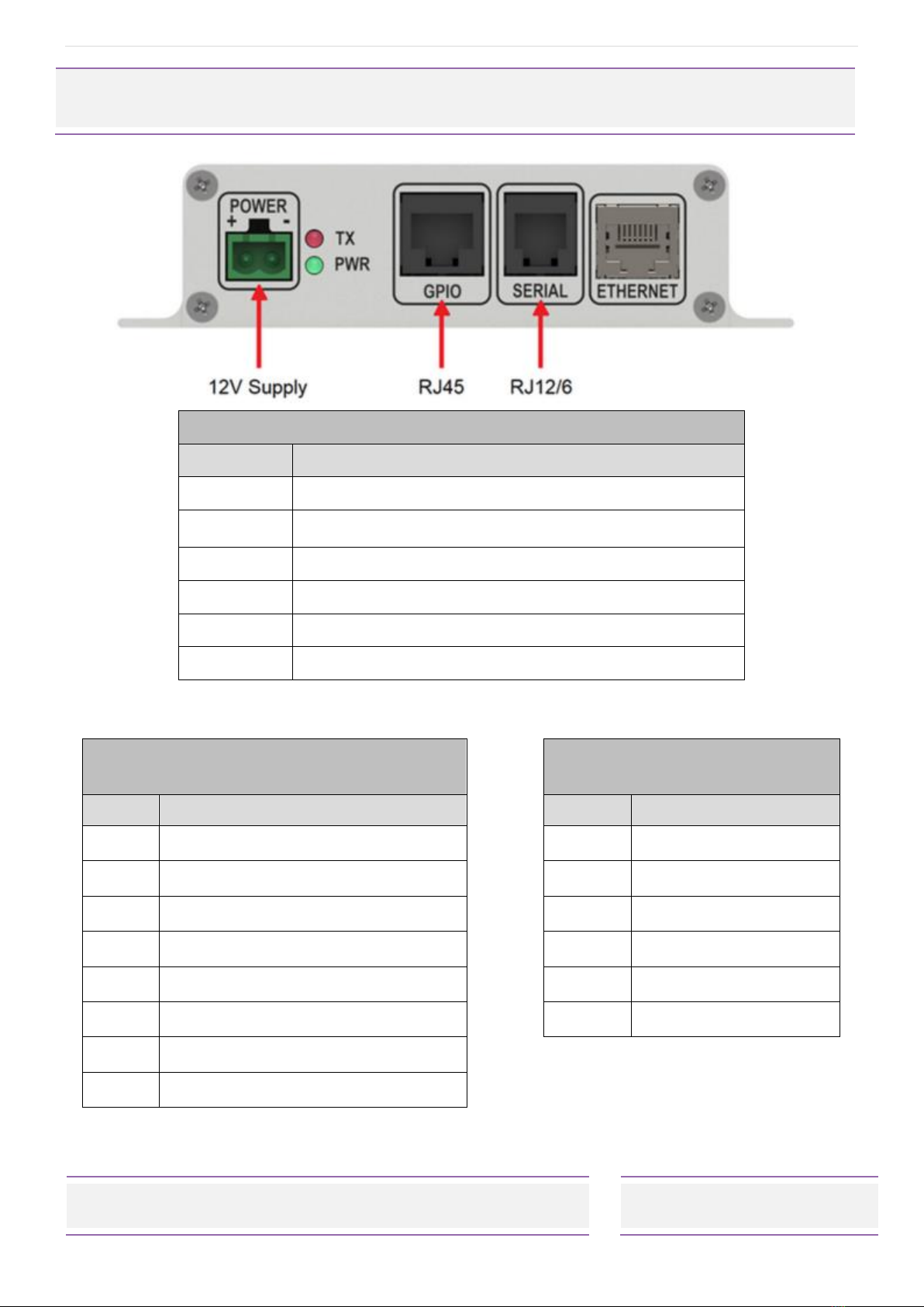
Serial and Ethernet ports: The 20-90 may be controlled through either an RS-232 serial port
or a TCP/IP or UDP Ethernet connection. Received messages may be directed to the serial
port, the Ethernet port or both.
Sacoto configuration tool: The Salcom “Sacoto” configuration software allows full
configuration of all functions of the 20-90 transceiver via the serial port or the Ethernet port.
Store & Forward repeater: The 20-90 can be configured to operate autonomously as a
store & forward repeater. Received messages can be retransmitted by the 20-90 to
provide infill paging in weak signal areas, or extend the range of other low power
transmitters. The 20-90 provides a duplicate reject function to prevent loops and
unintended retransmissions.
Input triggered messages: The 20-90 provides up to 5 inputs which can trigger message
transmissions. Messages may be triggering at power up, on the rising or falling edges with
a programmable de-bounce delay, or a using regular watchdog timer. Messages may be
repeated several times with a programmable interval between transmissions.
Relays and open drain outputs: The 20-90 supports the Salcom relay control protocol to
control up to 7 outputs: two on board relays, two high current open drain outputs with
resettable fuses, plus three low current open drain outputs with a 5 mA current limit.

P a g e | 5
20-90 VHF & UHF TRANSCIEVER
Product Manual
Sea Air and Land Communications Ltd, 10 Vanadium Place, Addington, Christchurch 8024, New Zealand September 2021
Acknowledgement messages: An acknowledgement message can be triggered when
an output has been activated by receipt of a valid message. An acknowledgment is not
sent if there is an overcurrent fault on the output. An acknowledgement may be triggered
for any received message within a programmed range of CAP codes.
Special functions: Salcom relay control protocol or CAP code ranges may be used to
remotely trigger various special functions or transmit stored messages on the 20-90. These
may be used to: acknowledge messages; report the battery level, request the received
signal strength; request a checksum of the received message; trigger messages to report
the current input state; report the state of all inputs and outputs; or restart the 20-90.
POCSAG rapid: POCSAG rapid is a special application of the POCSAG protocol which
provides a faster response to the press and release of a button than full POCSAG messages
would allow. This allows faster and more accurate time-critical control. The 20-90 supports
both the transmission and reception of POCSAG rapid at up to 2400 baud.
Busy Detect: The 20-90 provides a channel busy function to prevent message collision or
corruption which reduces the need to retransmit messages and increases confidence of
delivery. An output may be configured to provide a channel busy indication to another
(higher power) transmitter.
Additional I/O: Expansion of the 20-90 I/O is possible through the use of the 20-03 expansion
module, allowing any number of inputs or outputs to be supported.

P a g e | 6
20-90 VHF & UHF TRANSCIEVER
Product Manual
Sea Air and Land Communications Ltd, 10 Vanadium Place, Addington, Christchurch 8024, New Zealand September 2021
Connectors and Indicators
Pin 1 on left side when viewed from front, as above.
Table 1: Connectors and Indications (L-R)
Item
Description
1
12V Supply
2
TX/Busy LED (Red): Flashing=TX, Solid=channel busy
3
Power LED (Green): Slow blink = ok, Fast = error
4
GPIO: Relays and High current I/O (RJ45)
5
Serial: Serial port and Low current I/O (RJ12)
6
Ethernet (RJ45)
Table 2: GPIO connector
(RJ45)
Table 3: Serial connector
(RJ12)
Pin
Connection
Pin
Connection
1
I/O 4 (500mA)
1
Ground
2
I/O 3 (500mA)
2
I/O 5 (5mA)
3
Relay 2 Normally Open contact
3
I/O 6 (5mA)
4
Ground
4
I/O 7 (5mA)
5
Relay 2 Common contact
5
RS232 TXD
6
Relay 1 Normally Open contact
6
RS232 RXD
7
a
Relay 1 Normally Closed contact
8
Relay 1 Common contact

P a g e | 7
20-90 VHF & UHF TRANSCIEVER
Product Manual
Sea Air and Land Communications Ltd, 10 Vanadium Place, Addington, Christchurch 8024, New Zealand September 2021
Physical Dimensions
The 20-90 has an extruded aluminum case with a mounting flange and screw slots. A
dimensioned drawing is provided below.

P a g e | 8
20-90 VHF & UHF TRANSCIEVER
Product Manual
Sea Air and Land Communications Ltd, 10 Vanadium Place, Addington, Christchurch 8024, New Zealand September 2021
20-90 Installation and Quick Start Guide
Power Supply
Power is connected to the green “Power”connector on the front panel with the polarity as
shown. Nominal supply voltage is 13.8V DC, but may vary between 10.8V and 15V. The power
source must be reasonably noise free. The 20-90 is protected against reversed polarity.
Antenna Installation
The antenna is connected to the SMA connector on the rear panel. Installing the antenna
outside, clear of obstacles, and high above the ground will most likely provide the best radio
coverage. A whip antenna may be connected directly to the SMA connector for more
convenient installation where range is not a concern.
The antenna should present a nominal load of 50Ω, with a VSWR of better that 1.8:1. Performance
may be reduced by a poorly matched antenna (i.e. not 50 ohms at the transmitter frequency).
When used as a Store and Forward repeater in a weak signal area, the antenna should be
positioned for best reception, while still providing transmit coverage into the weak signal area.
Important! To comply with FCC Controlled/Occupational Exposure Limits the aerial must be
positioned or mounted to operate at least 0.26 metres (0.853 ft) away from operational staff and
0.57 metres (1.87 ft) away from the general public as a safeguard against radiated emissions.
Serial and Ethernet connections
The 20-90 may be configured to operate without a serial or Ethernet connection by: transmitting
regular messages; transmitting messages in response to inputs or received messages; operating
outputs in response to received messages; or acting as a store and forward repeater.
For transmitting other messages, or monitoring received messages, the RJ12 serial connector,
used with the Salcom 12-45 RJ-12 to DB-9 adaptor, provides an RS-232 serial port at 9600 baud,
8N1. Connection may also be made via the Ethernet port, as a TCP or UDP, server or client.
The Ethernet IP address, ports, masks and connection modes can be configured using Salcom’s
Sacoto configuration software.
Powering-Up
When powered up the GREEN power indicator should flash once per second to indicate normal
operation. A rapid GREEN flash indicates a low battery voltage.
The RED indicator will blink for a few seconds at power up if there is a problem. Error messages
are sent to the serial port.

P a g e | 9
20-90 VHF & UHF TRANSCIEVER
Product Manual
Sea Air and Land Communications Ltd, 10 Vanadium Place, Addington, Christchurch 8024, New Zealand September 2021
Configuration
The 20-90 can be entirely configured using the Salcom “Sacoto” configuration tool. Basic
configuration such as frequency, baud rate, Ethernet configuration, output configuration, and
input triggered messages are covered in the Sacoto Quick Start Guide later in this manual.
Message transmission
Standard serial COM port Terminal software can be used to initiate messages using Salcom
Message Protocol.
For example sending the text CA1234567 1 Hello, terminated with a carriage return (ASCII 13),
will initiate a 512 baud paging message, sent to CAP code 1234567.
The RED TX indicator will flash rapidly when the unit is transmitting.
A solid RED indicator indicates that the channel is busy. Transmission will start when the channel
becomes clear. Chanel busy conditions and thresholds can be configured using Sacoto.
Messages can be initiated over the Ethernet TCP or UDP connection. This uses the same
commands as the serial connection. Connecting via Ethernet is described later in this manual.
An Ethernet test tool is provided to assist the initial setup and may be used as a basic interface
for sending and monitoring paging messages using the Ethernet connection.
Messages can be triggered by inputs, by a watchdog timer, or as a response to a received
message. This is described later in this manual.
Received messages
Received messages can be filtered by CAP code, and are sent over the serial or Ethernet
interface using Salcom Message Protocol.
Received messages may be sent to a higher power transmitter, such as the Salcom 20-62, for
store and forward operation, or to a Salcom 20-03 I/O expansion unit to provide additional relay
and open collector outputs.
The receive baud rate and message type is specified on the POCSAG tab of Sacoto.

P a g e | 10
20-90 VHF & UHF TRANSCIEVER
Product Manual
Sea Air and Land Communications Ltd, 10 Vanadium Place, Addington, Christchurch 8024, New Zealand September 2021
Salcom Message Protocol
Messages are transmitted or received using Salcom Message Protocol (Salcom Protocol) over
the serial or Ethernet ports.
Salcom protocol takes the basic form: PPXXXXXXX L MMMMMM<CR>
Where:
PP can be “CA”, “CN”, “ca”, “cn”, “Ca”, or “Cn”
Upper case “CA” or “CN” denotes 512 baud
Lower case “ca” or “cn” denotes 1200 baud
Mixed case “Ca” or “Cn” denotes 2400 baud
“A” denotes Alphanumeric, “N” denotes Numeric
XXXXXXX is a 7 digit CAPcode (Pager number)
Spaces as shown
L is the function code (beep level) from 1 to 4.
MMMMM is the message (up to 240 characters).
<CR> is a carriage return (enter key).
Alphanumeric messages
Usage: CA<pager#>[<space>]<level>[<space>]<message><CR>
Description: Call alphanumeric pager
Example: CA1119358 1 Please return to reception<CR>
Response: CA11193581<CR><SPACE>Page Sent<CR><LF>
Numeric Messages
Usage: CN<pager#>[<space>]<level>[<space>]<message><CR>
Description: Call numeric pager
Example: CN1119358 1 777<CR>
Response: CN11193581<CR><SPACE>Page Sent<CR><LF>
Tone Only Paging
Usage: CN<pager#>[<space>]<level><CR>
Description: Call pager with beeper only (no message). One of 4 tone options <level>
Example: CN1119358 1<CR>
Response: CN11193581<CR><SPACE>Page Sent<CR><LF>

P a g e | 11
20-90 VHF & UHF TRANSCIEVER
Product Manual
Sea Air and Land Communications Ltd, 10 Vanadium Place, Addington, Christchurch 8024, New Zealand September 2021
Channel Busy Detection
The 20-90 provides a channel busy function to prevent transmission when the channel is in use, or
when there is interference on the channel. An output may be configured to provide this busy
indication to an external high power transmitter or other channel activity indicator.
TX/BUSY Indicator LED
A rapidly flashing red LED indicates that the 20-90 is transmitting.
A solid red LED indicates channel activity, and may inhibit the transmitter.
Receiving a message: The TX/BUSY LED is on (solid) whenever a message is being received.
Normally the 20-90 transmitter will be inhibited when a message is
being received. This can be disabled in cases where unwanted
weak signals may block the transmitter but would not interfere with
local reception. The RSSI threshold may be used instead to detect
local signals or interference.
RSSI threshold: Other signals or interference on the channel can be detected by the
received signal strength (RSSI). When enabled, the TX/Busy LED will
be on whenever the received signal strength is above the RSSI
threshold level. The transmitter will be inhibited until the channel is
clear again.
Busy Hold time: This is the delay between the channel becoming clear and the
transmitter being free to transmit. This delay reduces the flickering of
the busy state with rapidly fluctuating interference. The delay may
be increased as required. Maximum delay is 5 seconds.
The Busy Hold time also controls the delay between receiving a
message and any response from the 20-90, including
acknowledgements, special function replies, or store and forward.
Using a different delay for each transmitter can help control channel
access when multiple transmitters are waiting to transmit.
Busy Output: An output on the 20-90 may be used to provide a channel busy
signal. The CLOSED state (low) represents a busy channel. This output
mirrors the internal transmit inhibit function. The output will be closed
if the signal strength is above the threshold when the RSSI threshold is
enabled, or a messages is being received and “Receive State” is
enabled.

P a g e | 12
20-90 VHF & UHF TRANSCIEVER
Product Manual
Sea Air and Land Communications Ltd, 10 Vanadium Place, Addington, Christchurch 8024, New Zealand September 2021
CAP codes
Every paging message includes a CAP code (Channel Access Protocol). This is normally the
pager number to which the message is addressed. The CAP code can also be known as a RIC
(Radio Identity Code). CAP codes may be unique to a specific pager, or shared by a number of
pagers within a group.
A pager may respond to multiple CAP codes, and may respond differently to each range.
Multiple pagers may respond to the same CAP code (a broadcast to a group) in addition to a
CAP code which is unique to that pager.
Ranges of CAP codes may be assigned different purposes. Ranges may identify the message
type being transmitted (Numeric or Alphanumeric). Ranges may also be used to filter messages
by network or group, or for some other purpose.
Decode filter
The 20-90 provides up to 8 CAP code ranges. It will only decode messages that are within one or
more of these ranges (inclusive). The default range is 0000008 to 2000000. The ranges may be in
any order, and may overlap. A CAP code range can be limited to just one CAP code if desired.
Triggering outputs
An output may be closed or opened in reception of a CAP code with a range. Closing an
output may be used to trigger a mono-shot output if the mono-shot time is non-zero on the
output tab. The output will automatically open after the mono-shot time.
CAP code range triggering outputs provides a method of monitoring messages within a range
without the need to include relay protocol in each message.
The output may be used to trigger an acknowledgment message, which can include special
function messages like received RSSI or received message checksum. The same range may be
specified more than once to trigger more than one output or special function.
When used with a mono-shot time to monitor a remote watchdog, the opening transition may
be used to trigger the transmission of an alert message.
POCSAG Rapid
Tone only messages may be sent using POCSAG rapid for fast relay control. Since tone only
messages do not include relay protocol, a CAP code range is used to trigger the desired output.
POCSAG rapid uses 8 CAP codes, starting at a multiple of 8. See the POCSAG Rapid section
below.

P a g e | 13
20-90 VHF & UHF TRANSCIEVER
Product Manual
Sea Air and Land Communications Ltd, 10 Vanadium Place, Addington, Christchurch 8024, New Zealand September 2021
Input and Output Operation
The 20-90 has two Relay outputs and five combined I/O pins. These operate as follows:
20-90 Inputs and Outputs are active low.
The low state is referred to as “Closed”, referring to a closed switch to ground, or an
active open-drain output pulling the I/O pin to ground.
An energized relay is referred to as “Closed” (the normally-open contact is closed).
When an open-drain output is “Open” (inactive), an internal pull up resistor allows the
I/O pin to be used as an input.
An external switch may pull the I/O pin to ground, triggering a transmission if the 20-90 is
configured to do so. A message may also be transmitted when the switch is opened.
Inputs:
The 20-90 monitors the state of each I/O pin at all times.
The 20-90 can be configured to transmit a message when an I/O pin changes state.
Separate messages are defined for open and closed states. Transmission of either or
both messages may be enabled or disabled.
The message corresponding to the input state may be transmitted at startup, or with a
regular “watch dog” timer.
Since inputs and outputs are combined on the same pin, changes to an output can be
monitored and acknowledged by configuring the input messages for the I/O pin. This
can also detect if the output protection or current limits have been activated.
Input messages can be defined for I/O channels which are not physically implemented.
These can be triggered by the relay protocol or a range of CAP codes as a form of
acknowledgement without changing the state of any physical I/O pins.
Input messages may be defined for relays to provide an acknowledgement of the
received message.
Outputs:
Each output can be opened or closed using Salcom Relay Control Protocol (described
below). This may be in a received message, or as a command over the serial or Ethernet
ports.
Each output can be disabled to ensure that no received message can affect the input.
An output may be configured with a “Monoshot” timer, to automatically open after a
specified time.
Outputs can be closed when a message is received that has a CAP code which is within
a specified range. This can be useful for monitoring received transmissions, or for
transmitting acknowledgements. This feature is also used for POCSAG rapid.
The Relay protocol, or a CAP code range, may activate “virtual” outputs, which are not
physically implemented, but can trigger special functions within the 20-90. For example,
a special function may transmit an acknowledgement which includes the received
signal strength or a checksum of the received message. See “special functions”.

P a g e | 14
20-90 VHF & UHF TRANSCIEVER
Product Manual
Sea Air and Land Communications Ltd, 10 Vanadium Place, Addington, Christchurch 8024, New Zealand September 2021
Salcom Relay Control Protocol
Salcom Relay Control Protocol (relay protocol) is used to control relays or other outputs; or to
trigger acknowledgement messages or special functions of the 20-90.
A relay protocol control string can be sent as numeric or alpha-numeric messages. Numeric
messages are shorter, and are therefore more efficient to transmit. The receiver must be
configured to receive the correct message type.
A relay protocol command is addressed to a specific “unit ID”. Each unit ID can control up to 8
outputs.
A single unit may have multiple unit ID’s to address more than 8 outputs or special functions.
The relay control string can be embedded anywhere within the message e.g. “CLOSE RELAY ONE
10109”. However, the first two digits of any string of digits is always the unit ID. Multiple relay control
strings can be contained in one message, each addressing a different unit ID.
The unit ID should not be a number that regularly appears anywhere in your typical messages
where it may be followed by more digits. This is to avoid the likelihood of false commands.
Command Format:
UUC..C0N..N9S
UU Unit ID:
This must be 2 digits from 00 - 99.
COutputs to Close
Multiple outputs may be specified, from 1 to 8 in sequential order.
0End of Closed Outputs
“0” terminates the list of outputs to close. This character in mandatory.
NOutputs to Open
Multiple outputs may be specified, from 1 to 8 in sequential order.
9End of Open Outputs
“9” terminates the list of outputs to open. This terminating digit is required to
consider this as a valid control string.
S Optional Checksum
If the checksum is enabled, the modulo-10 sum of relay protocol digits, including
the checksum digit, must sum to 0 to be considered a valid command.
The 20-90 uses four Unit ID’s, starting at the Base ID specified in in the System > Relay Protocol Tab
of Sacoto.

P a g e | 15
20-90 VHF & UHF TRANSCIEVER
Product Manual
Sea Air and Land Communications Ltd, 10 Vanadium Place, Addington, Christchurch 8024, New Zealand September 2021
20-90 Output Map
Base ID + 0
I/O
Channel
Output
Function
Description
1
1
Relay 1 (RJ45)
Normally open and normally closed contacts
2
2
Relay 2 (RJ45)
Normally open contacts only
3
3
Output 3 (RJ45)
500mA open drain output with resettable fuse
4
4
Output 4 (RJ45)
500mA open drain output with resettable fuse
5
5
Output 5 (RJ12)
Open drain output with 5mA current limit
6
6
Output 6 (RJ12)
Open drain output with 5mA current limit
7
7
Output 7 (RJ12)
Open drain output with 5mA current limit
8
8
Message 8 (Internal)
Trigger open and close messages
Base ID + 1
I/O
Channel
Output
Function
Description
9
1
Message 9 (Internal)
Trigger open and close messages
10
2
Message 10 (Internal)
Trigger open and close messages
Base ID + 2
Not used
Base ID + 3 Trigger special functions - see “Special Functions” below.
I/O
Channel
Output
Open function
Relay
protocol
Close Function
Relay
protocol
30
6
Checksum
23069
Reset
23609
31
7
I/O status
23079
RSSI
23709
32
8
Battery level
23089
Watchdog
23809
Relay protocol example given for a unit base ID of 20.

P a g e | 16
20-90 VHF & UHF TRANSCIEVER
Product Manual
Sea Air and Land Communications Ltd, 10 Vanadium Place, Addington, Christchurch 8024, New Zealand September 2021
Special Functions
The 20-90 supports 6 “special functions”. These are triggered by relay protocol, using the base unit
ID + 3, or by a CAP code range configured to “open” or “close” output channels 30, 31, or 32 on
receipt of a matching CAP code.
In the following examples the 20-90 Base ID is configured as 00 (default), thus Base ID + 3 = 03.
The response includes the unit ID of the unit sending the response, a letter to identify the function,
and the response data.
Extra text is included in the command message but only the relay protocol command is required.
Checksum: 03069
When a received message triggers the checksum function, the 20-90 will wait until the channel is
clear then transmit an alphanumeric message containing the checksum of the message that
activated it.
Message received: CA1234567 1 Checksum test 03069
Transmitted response: CA1234560 1 00:C:b6
The checksum function may be triggered without including the relay protocol command by
configuring the receiving 20-90 to Open I/O channel 30 if the received cap code is 1234560 to
1234567 (or any other range that includes the messages that a checksum is required for).
Other functions can be triggered by configuring a CAP code range to open or close other I/O
channels.
I/O Status: 03079
The I/O status function will read the current state of all inputs and outputs (including
unimplemented I/O channels) and report the current state (closed=1). Inputs will be the same as
the outputs unless external circuitry is pulling the pin up or down.
Message received: CA1234567 1 Report I/O status 03079
Transmitted response: CA1234560 1 00:I:00000000:O:00000000
Battery Level: 03089
Reports the battery level when triggered.
Message received: CA1234567 1 Report battery level 03089
Transmitted response: CA1234560 1 00:B:13.8

P a g e | 17
20-90 VHF & UHF TRANSCIEVER
Product Manual
Sea Air and Land Communications Ltd, 10 Vanadium Place, Addington, Christchurch 8024, New Zealand September 2021
Reset: 03609
Resets the 20-90. Any messages configured to transmit at power up will be transmitted following
the reset. There is no other response.
Message received: CA1234567 1 Reset 20-90 03609
Unit response: Reset
Report RSSI: (Received Signal Strength Indicator) 03709
When a received message triggers the RSSI function, the 20-90 will wait until the channel is clear
then transmit an alphanumeric message containing the received signal strength, in dBm, of the
message that activated it.
Message received: CA1234567 1 Report RSSI 03709
Transmitted response: CA1234560 1 00:-29dBm
Trigger Watchdog: 03809
This function can be used to force a watchdog response in between regular watchdog events, or
to trigger the watchdog when the timer is not operating (watchdog repeat time = 0).
Regardless of whether the watchdog timer is operating or not, any messages that are configured
to be sent with the watchdog timer will be transmitted, including any inputs configured as “with
watchdog” and the watchdog message (if enabled).
This function may be used to check if a unit is operating (message only), or to read back the state
of inputs that have been configured to be sent with the watchdog.
Watchdog: Enabled
Watchdog message: 512A 1234567 1 Watchdog Test
Received message: CA1234560 1 Trigger watchdog 03809
Transmitted message: CA1234567 1 Watchdog Test
Special function CAP code, baud rate and level
Except where defined by the input or watchdog messages, the default CAP code and default
transmit baud rate is used (configured under the CAP codes and Transceiver tabs in Sacoto). The
function level for special function messages is always “1”.

P a g e | 18
20-90 VHF & UHF TRANSCIEVER
Product Manual
Sea Air and Land Communications Ltd, 10 Vanadium Place, Addington, Christchurch 8024, New Zealand September 2021
POCSAG Rapid
POCSAG rapid allows a faster response to a push button input. POCSAG rapid uses a short
preamble, and starts the message transmission in the first POCSAG frame, regardless of the CAP
code. For even faster response, keep messages short, use numeric or tone only messages, reduce
the de-bounce time, and consider using 1200 or 2400 baud.
The transmitted CAP code will be a multiple of 8. The POCSAG frame number is part of the full
CAP code, and POCSAG rapid always starts in frame 0.
POCSAG rapid would be used without “while held” for separate “open”and “close”buttons.
While Held
The “While Held” option sends messages continuously while the input is in the specified state.
When used with POCSAG rapid, messages are transmitted continuously in all eight frames of the
POCSAG data stream, until the input is released. This allows the receiver to use a short mono-shot
timer on the output, providing quick push-button release response (momentary action).
The transmitted CAP code will be a multiple of 8 plus the slot position, from 0 to 7. A long enough
transmission will cycle through all 8 CAP codes the start over. A receiver should be configured to
respond to all eight CAP codes.
Mono-shot Delays
The fastest release response can be achieved by reducing the mono-shot delay to the minimum
required to guarantee that the output will be retriggered before the mono-shot times out.
Minimum delays (seconds) are as follows:
Message type
512 Baud
1200 Baud
2400 Baud
Tone only:
Output defined by
CAP code range
0.150
0.075
0.050
Numeric:
Relay protocol, up to
10 digits
0.275
0.150
0.075
Alpha-numeric:
Relay protocol, up to
14 characters.
0.400
0.175
0.100
Note: POCSAG rapid is not intended to work with pagers.

P a g e | 19
20-90 VHF & UHF TRANSCIEVER
Product Manual
Sea Air and Land Communications Ltd, 10 Vanadium Place, Addington, Christchurch 8024, New Zealand September 2021
Watchdog messages
Watchdog Function
The watchdog function provide a means of generating periodic transmissions. These may be
regular “I’m alive” messages which can be monitored by a receiver to determine the
operational status of a remote transmitter. Another 20-90 can monitor these messages and
provide an alert message if the watchdog transmissions stop. Both 20-90’s may be configured to
monitor each other for even greater reliability.
Regular transmission of input messages
The watchdog timer may also be used to send messages to monitor inputs. Any input message
may be configured to be sent “with watchdog”. The general watchdog message may be
disabled without affecting input messages sent with the watchdog timer.
The watchdog timer is disabled by setting the period to zero.
Triggering the Watchdog with Relay Protocol
Even if the watchdog timer is disabled, the watchdog messages may still be triggered by using
the “trigger watchdog” special function, described above.
This allows remote reading of the selected inputs at any time.
Monitoring a remote watchdog message
A relay protocol command maybe included in a watchdog message to trigger an output on the
monitoring 20-90. If the mono-shot time is longer than the watchdog period then the output will
remain closed as long as the watchdog message continues to be transmitted. The maximum
mono-shot time is 24 hours. It is recommended that the mono-shot time be at least twice the
watchdog period, in case one watchdog message is not received due to interference.
The output on the monitoring 20-90 will open if the watchdog message is not received, providing
an indication that the remote transmitter is not functioning correctly.
The opening of this output may be used to trigger a transmission by the monitoring 20-90 to
provide an alert message when the remote transmitter has stopped working. Two or more 20-90s
may monitor each other’s watchdog transmissions.
Using CAP code ranges instead of relay protocol to trigger the output allows multiple 20-90’s to
monitor the same watchdog transmission without needing to include the unit ID of every
monitoring unit in the watchdog message. Only one remote transmitter should be monitored by
a range, and only one remote transmitter per output.
Table of contents
Other Salcom Transceiver manuals
Popular Transceiver manuals by other brands

Technisonic Industries Limited
Technisonic Industries Limited TFM-556 Installation and operating instructions

Intel
Intel Stratix 10 user guide

Yaesu
Yaesu FT-857 series Technical supplement

Yaesu
Yaesu FT-411 MKII Technical supplement

MGL Avionics
MGL Avionics V10 User and installation manual

Allied Telesis
Allied Telesis CentreCOM AT-MX70 10BASE2 user manual