Salda RIRS 400 V EKO 3.0 Series Guide

RIRS 400-700 V EKO 3.0
EN MOUNTING AND INSTALLATION INSTRUCTION

2 | EN RIRS 400-700 V EKO 3.0 v2019.06
CONTENT
2.SYMBOLS AND MARKING 3
3.SAFETY INSTRUCTIONS AND PRECAUTIONS 3
4.DIMENSIONS AND WEIGHT 4
5.ELECTRICAL DATA 4
6.CONSTRUCTION 5
7.OPERATING CONDITIONS 6
8. PACKAGE 6
9.TRANSPORTATION 6
10. UNPACKING 7
11. STANDART PACKAGE OF COMPONENTS 7
12. PLACE REQUIREMENTS 7
13. MOUNTING 7
14.CONNECTION OF THE AIR DUCT 8
15.CONNECTION DIAGRAM 8
16.CONNECTION OF THE UNIT TO ELECTRIC NETWORK 9
17.START-UP RECOMMENDATIONS 9
17.1.RECOMMENDATIONS BEFORE THE START OF THE UNIT (BEFORE THE FINAL USER) 9
17.2.POSSIBLE FAULTS AND TROUBLESHOOTING 9
18.MAINTENANCE 9
18.1. FILTERS 9
18.2. FAN 10
18.3. HEAT EXCHANGER 10
18.4. ELECTRICAL HEATER 10
19.AUTOMATIC CONTROL 11
19.1. SYSTEM PROTECTION 12
19.2. USING THE UNIT IN BMS NETWORK 12
19.3. MODBUS ADRESSES 13
19.4.ELECTRICAL CONNECTION OF THE HVAC UNIT 14
19.5. SYSTEM ADJUSTMENT GUIDELINES 14
20.CONTROL BOARD RG1 15
20.1.LABELING, CHARACTERISTICS OF THE CONTROLLER AND THE SYSTEM COMPONENTS 16
20.2. REGULAR SYSTEM CHECK-UP 18
21.ELECTRICAL CONNECTION DIAGRAM 19
21.1. RIRS 400 VE EKO 3.0 19
21.2. RIRS 400 VW EKO 3.0 20
21.3. RIRS 700 VE EKO 3.0 21
21.4. RIRS 700 VW EKO 3.0 22
22.ECODESIGN DATA TABLE 23
23.DECLARATION OF CONFIMITY 25
24. WARRANTY 26
24.1. LIMITED WARRANTY COUPON 26

EN | 3RIRS 400-700 V EKO 3.0 v2019.06
2. SYMBOLS AND MARKING
LN: XX000000
2019.01.01
Figure. 2.1. Technical label
1 - Logo; 2 - Product code (SKU); 3 - Product name; 4 - Technical data; 5 - Production place; 6 - Lot number and production date; 7 - Serial
number.
SERIAL
2514523357
XXXGAMINIOPAVADINIMAS
Nominalvoltagefrequency
Max.current
Max.powerconsumption
Protectionclass
Weight
/ xxx/xx VAC/Hz
x.xxA
x.xxkW
IPxx
xxkg
MadeinŠiauliai, Lithuania
AHU000000
BN:xxxxxx
2019/01/01
SERIAL
2514523357
XXXGAMINIOPAVADINIMAS
Nominalvoltagefrequency
Max.current
Max.powerconsumption
Protectionclass
Weight
/xxx/xxVAC/Hz
x.xxA
x.xxkW
IPxx
xxkg
MadeinŠiauliai, Lithuania
AHU000000
BN:xxxxxx
2019/01/01
SERIAL
2514523357
XXXGAMINIOPAVADINIMAS
Nominalvoltagefrequency
Max.current
Max.powerconsumption
Protectionclass
Weight
/ xxx/xx VAC/Hz
x.xxA
x.xxkW
IPxx
xxkg
MadeinŠiauliai, Lithuania
AHU000000
BN:xxxxxx
2019/01/01
SERIAL
2514523357
XXXGAMINIOPAVADINIMAS
Nominalvoltagefrequency
Max.current
Max.powerconsumption
Protectionclass
Weight
/ xxx/xx VAC/Hz
x.xxA
x.xxkW
IPxx
xxkg
MadeinŠiauliai, Lithuania
AHU000000
BN:xxxxxx
2019/01/01
SERIAL
2514523357
XXX GAMINIO PAVADINIMAS
Nominal voltage frequency
Max.current
Max.power consumption
Protection class
Weight
/ xxx/xx VAC/Hz
x.xxA
x.xx kW
IP xx
xx kg
Made in Šiauliai, Lithuania
AHU000000
BN:xxxxxx
2019/01/01
SERIAL
2514523357
XXX GAMINIO PAVADINIMAS
Nominal voltage frequency
Max.current
Max.power consumption
Protection class
Weight
/ xxx/xx VAC/Hz
x.xxA
x.xx kW
IP xx
xx kg
Made in Šiauliai, Lithuania
AHU000000
BN:xxxxxx
2019/01/01
SERIAL
2514523357
XXX GAMINIO PAVADINIMAS
Nominal voltage frequency
Max.current
Max.power consumption
Protection class
Weight
/ xxx/xx VAC/Hz
x.xxA
x.xx kW
IP xx
xx kg
Made in Šiauliai, Lithuania
AHU000000
BN:xxxxxx
2019/01/01
SERIAL
2514523357
XXX GAMINIO PAVADINIMAS
Nominal voltage frequency
Max.current
Max.power consumption
Protection class
Weight
/ xxx/xx VAC/Hz
x.xxA
x.xx kW
IP xx
xx kg
Made in Šiauliai, Lithuania
AHU000000
BN:xxxxxx
2019/01/01
Figure. 2.2. Technical label place
Figure. 2.3. Indication for duct connection.
ODA - outdoor air; SUP - supply air; ETA - extract air; EHA - exhaust air.
3. SAFETY INSTRUCTIONS AND PRECAUTIONS
Read this instruction very carefully before installing and using this equipment. Installation, connection and maintenance should be carried out by
a qualifed technician and in accordance with the local rules and legal acts.
The company shall take no responsibility for the injuries suered by the people or for the damaged property, if the safety requirements are not
followed or the device is modifed without the permission of the manufacturer.
Warning – pay attention Additional information
Main safety rules
Danger
• Before performing any electricity or maintenance tasks make sure, that the device is disconnected from the mains, that all moving parts
of the device have stopped.
• Make sure that the fans can not be entered through air ducts or branch openings.
• If you notice liquids on electric parts or connections that bear voltage, stop the operation of the appliance.
• Do not plug the device into the mains, that diers from the one indicated on the label or on the housing.
• Voltage of the mains should comply with the electrotechnical parameters indicated on the label.
• The device should be earthed in accordance with the rules of installation of electric appliances. It is forbidden to turn on and use un-
earthed device. Follow the requirements of the device’s labels that indicate Danger.

4 | EN RIRS 400-700 V EKO 3.0 v2019.06
Warnings
• Connection of electricity and maintenance of the device should be performed only by a qualied personnel, in accordance with the
manufacturer’s instructions and valid safety requirements.
• In order to reduce the risk during installation and maintenance, suitable protective clothes should be worn.
• Beware of sharp angles while performing installation and maintenance tasks.
• Do not touch heating elements until they haven’t cooled down.
• Some devices are heavy, thus one should be very careful while transporting and installing. Use suitable lifting equipment.
• While connecting electricity to the mains a circuit breaker of suitable size is necessary.
Warning!
• If the device is installed in a cold environment, make sure that all connections and tubes are properly isolated. Intake and discharge air
ducts should be isolated in all cases.
• Openings of the ducts should be covered during transportation and installation.
• Make sure not to damage the heater when connecting the piping of the water heater. For tightening up, use a wrench/spanner.
Before starting the equipment
• make sure, that there are no strange objects inside;
• manually check whether fans are not stuck or blocked;
• if rotary heat exchanger is installed in the device, make sure that it is not stuck or blocked;
• check the grounding;
• make sure that all components and accessories are connected in accordance with the project or provided instructions.
Danger: Fumes
Salda Antifrost system uses dis-balancing of the air ow and it may cause negative pressure in premises. Great care should be taken
when using at the same time in premises as another heating appliance what depend on the air in premises. Such appliances include
gas, oil, wood or coal-red boilers and heaters, replaces, continuous ow or other water heaters, gas hobs, cookers or ovens which
draw air in from the room and duct exhaust gases out through a chimney or extraction ducting. The heating appliance can be starved
of oxygen, impairing combustion. In exceptional cases harmful gases could be drawn out of the chimney or extraction ducting back
into the room. In this case we strictly recommend to turn o Salda Antifrost and use an external preheater for heat exchanger anti-frost
protection (see Salda Antifrost function on the Remote controller manual).
4. DIMENSIONS AND WEIGHT
L W H H1 øD F
RIRS V EKO 3.0 [mm] [mm] [mm] [mm] [mm] [mm]
400 560 900 850 40 160 30,7
700 655 1100 980 40 250 41
* - depend on the unit.
m
RIRS EKO 3.0
400 VER 400 VEL 400 VWR 400 VWL 700 VER 700 VEL 700 VWR 700 VWL
[kg] 79,5 79,5 79,0 79,0 108,0 108,0 96 96
5. ELECTRICAL DATA
RIRS EKO 3.0 400 VEL 400 VER 400 VWL 400 VWR
Heater phase/voltage [50 Hz/VAC] ~1 ~1 AVS 200 AVS 200
power consumption [kW] 1,2 1,2

EN | 5RIRS 400-700 V EKO 3.0 v2019.06
Fans
phase/voltage [50 Hz/VAC] ~1 ~1 ~1 ~1
exhaust power/current [kW/A] 0,085 / 0,75 0,085 / 0,75 0,085 / 0,75 0,085 / 0,75
speed [min-1] 3200 3200 3200 3200
supply power/current [kW/A] 0,085 / 0,75 0,085 / 0,75 0,085 / 0,75 0,085 / 0,75
speed [min-1] 3200 3200 3200 3200
control input [VDC] 0-10 0-10 0-10 0-10
protection class IP-54 IP-54 IP-54 IP-54
Total power consumption power/current [kW/A] 1,38 / 5,94 1,38 / 5,94 0,18 / 1,60 0,18 / 1,60
Automatic control integrated + + + +
Thermal eciency 75% 75% 75% 75%
Insulation of walls [mm] 50 50 50 50
Cross-section of the power supply cable [mm²] 3x1,5 3x1,5 3x1,5 3x1,5
Circuit breaker* Poles 1 1 1 1
I [A] B10 B10 C2 C2
Filter class and dimensions exhaust [mm] 450x170x46 450x170x46 450x170x46 450x170x46
supply [mm] 450x170x46 450x170x46 450x170x46 450x170x46
RIRS EKO 3.0 700 VEL 700 VER 700 VWL 700 VWR
Heater
phase/voltage [50 Hz/VAC] ~1 ~1
AVS 250 AVS 250
power consumption [kW] 2.0 2.0
Fans
phase/voltage [50 Hz/VAC] ~1 ~1 ~1 ~1
exhaust power/current [kW/A] 0,222 / 1,8 0,222 / 1,8 0,217/1,88 0,217/1,88
speed [min-1] 3380 3380 3380 3380
supply power/current [kW/A] 0,216 / 1,71 0,216 / 1,71 0,214/1,76 0,214/1,76
speed [min-1] 3380 3380 3380 3380
control input [VDC] 0-10 0-10 0-10 0-10
protection class IP-44 IP-44 IP-44 IP-44
Total power consumption power/current [kW/A] 2,44 / 12,31 2,44 / 12,31 0,44 / 3,74 0,44 / 3,74
Automatic control integrated + + + +
Thermal eciency 75% 75% 75% 75%
Insulation of walls [mm] 50 50 50 50
Cross-section of the power supply cable [mm²] 3x1,5 3x1,5 3x1,5 3x1,5
Circuit breaker* Poles 1 1 1 1
I [A] B13 B13 C4 C4
Filter class and dimensions exhaust [mm] 545x260x46 545x260x46 545x260x46 545x260x46
supply [mm] 545x260x46 545x260x46 545x260x46 545x260x46
6. CONSTRUCTION
10
9
9
9
1 - Plate/rotor heat exchanger; 2 - Supply fan; 3 - Exhaust fan; 5 - Electrical/water heater/pre-heater; 6 - Control board; 7 - Extract air lters
(panel/pocket); 8 - Supply air lter (panel/pocket); 9 - Rotor engine.

6 | EN RIRS 400-700 V EKO 3.0 v2019.06
7. OPERATING CONDITIONS
+5 C
o
+40 C
o
-23 C
o
+40 C
o
+15 C
o
+40 C
o
+5 C
o
+40 C
o
-40 C
o
+40 C
o
+15 C
o
+40 C
o
+5 C
o
+40 C
o
-15 C
-10
o
oC
+40 C
o
+15 C
o
+40 C
o
-3 C
o
+40 C
o
8. PACKAGE
H
L
W
RIRS V EKO 3.0
H W L QUANTITY ON THE
PALLET
[mm] [mm] [mm] [units]
400 1055 785 1270 1
700 1210 795 1240 1
9. TRANSPORTATION
Figure. 9.1. Lifting with forklift.
Only a product placed on a pallet may be lifted in order to prevent damage to the casing.

EN | 7RIRS 400-700 V EKO 3.0 v2019.06
10. UNPACKING
Accessories may be packed together with the product. Prior to transporting the unit, rst unpack the accessories.
• Remove the lm from the unit.
• Remove the bracing packaging tape which keeps the protective proles.
• Remove the protective proles.
•After unpacking the unit, examine it to make sure that it it has not been damaged during transportation. The installation of damaged units is
prohibited!
• Verify that all ordered equipment are delivered before starting the installation. Any deviation from the ordered equipment must be reported to the
supplier of products.
11. STANDART PACKAGE OF COMPONENTS
RIRS EKO 3.0
400 VER 400 VEL 400 VWR 400 VWL 700 VER 700 VEL 700 VWR 700 VWL
KEY 291103 11111111
12. PLACE REQUIREMENTS
L
1,5xL
L
1,5xL
H
H
Min. distance to open the door - 1,5xL; Min. distance to open control box door - H > 400 mm.
13.MOUNTING
The protective lm is intended to protect the unit during transportation. It is recommended to remove the lm because other-
wise oxidation signs may occur.
Before every heating season the condensate tube shall be lled with water as indicated during the rst startup!
400mm

8 | EN RIRS 400-700 V EKO 3.0 v2019.06
14.CONNECTION OF THE AIR DUCT
D2 dimensions depend on unit.
15.CONNECTION DIAGRAM
* KE1 - used in electrical version. In horizontal version heater is positioned before supply fan; * KV1 - used in water version. For more informa-
tion please, check the manual. ** Possible to control.
M
CO2
Figure. 15.1. Indication for duct connection. Figure. 15.2. Ventilated premises
ODA - outdoor air; SUP - supply air; ETA - extract air; EHA - exhaust air.
LIST OF COMPONENTS
CPlate heat exchanger A1 Fire alarm damper actuator I
PV Supply air fan A2 Fire alarm damper actuator II
IF Extract air lter TJ Supply air temperature sensor
PF Supply air lter TL Outdoor air temperature sensor
IV Exhaust fan TE Exhaust air temperature sensor
KE1 Electric heater DTJ Extract air temperature and RH sensor
PE1 Electric pre-heater T2 Cooler changeover thermostat
KV2 Water pre-heater TV2 Water preheater temperature sensor
KV3 Water cooler TV3 Water cooler temperature sensor
DX DX cooler U3 PV pressure transmitter
M1 By-pass damper U4 IV pressure transmitter
M2 Outdoor air damper actuator CO2CO2sensor*
M3 Exhaust air damper actuator RH RH sensor*
M5 Water cooler valve motor PC Computer
M12 Water pre-heater valve actuator RC1 Stouch or SA-Control remote control panel
M14 Water cooler circulation pump RC2 Stouch, Flex or SA-Control remote control panel
M15 DX cooler valve actuator MB-Gateway Network module
M16 Water pre-heater circulation pump NET Network
RRotor heat exchanger
POSSIBLE PCB INPUTS/OUTPUTS
FA Fire alarm H1 Working indication output

EN | 9RIRS 400-700 V EKO 3.0 v2019.06
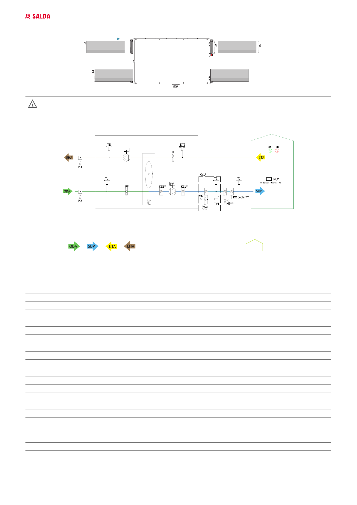
FPP Fireplace protection H2 Alarm indication output
System mode switch (START/STOP) Fans speed switch (BOOST)
* Component/posibility to connect it depends on model. For more information please, check the manual
16.CONNECTION OF THE UNIT TO ELECTRIC NETWORK
• Supply voltage to the unit must be connected by a qualied specialist following the manufacturer’s instructions and eective safety instructions.
• The unit’s power network voltage must correspond to electrotechnical parameters of the unit indicated in the technical decal.
• The unit’s voltage, power and other technical parameters are provided in the unit’s technical decal (on the unit casing). The unit must be connect-
ed to the voltage plug socket of the grounded power network in compliance with the eective requirements.
• The unit must be earthed according to the rules on installing electrical equipment.
• It is prohibited to use extension wires (cables) and power network plug socket distribution devices.
• Prior to carrying out any ventilation unit installation and connection activities (until its hand-over to the customer), the unit must be disconnected
from the power network.
• After installation of the ventilation unit, the power network plug socket must be accessible at any time and disconnection from the power network
is performed through the two-pole circuit breaker (by disconnecting phase pole and neutral).
• The unit must be thoroughly checked against damages (execution, control, measurement nodes) during transportation before it is connected to
the power network.
• The power cable can be replaced only by a qualied specialist upon the evaluation of the rated power and current.
The manufacturer does not assume any liability for personal injuries and property damage due to nonconformance with the
provided instructions.
17.START-UP RECOMMENDATIONS
17.1. RECOMMENDATIONS BEFORE THE START OF THE UNIT (BEFORE THE FINAL USER)
Prior to start-up the system must be thoroughly cleaned. Check whether:
• operation systems and unit elements as well as automation and automation devices were not damaged during installation,
• all electrical devices are connected to power supply and t for service,
• all necessary automation elements are installed and connected to power supply and terminal blocks,
• cable connection to terminal blocks comply with the existing power connection diagrams,
• all electrical equipment protection elements are properly connected (if they are additionally used),
• cables and wires correspond to all applicable safety and functional requirements, diameters, etc.,
• earthing and protection systems are properly installed,
• condition of all seals and sealing surfaces are proper.
17.2. POSSIBLE FAULTS AND TROUBLESHOOTING
FAILURE CAUSE EXPLANATION / CORRECTIVE ACTIONS
Unit is not operating
No supply voltage Check whether the device is connected to the
power network
Protection device is o or a current
leakage relay is active (if installed by the
installer)
Switch on only if the unit condition has been
evaluated by a qualied electrician. If the sys-
tem failed, the failure MUST BE rectied prior
to switching it on.
Air supply heater or pre-heater is not operat-
ing or malfunctioning (if installed)
Too low air ow in air ducts activates auto-
matic
protection
Check if air lters are not clogged
Check if fans are rotating
Manual protection is activated
Possible heater or unit failure. MUST contact
the servicing sta for failure detection and its
elimination.
Too low air ow at rated fan speed Clogged supply and/or extract air lter(s) Filter replacement needed
Filters are clogged and no message is shown
on the remote control
Wrong time in lter timers or their switch is
broken, or its pressure is set improperly.
Shorten lter timer time till the message of
clogged lters or replace the pressure switch
of the lters, or set their proper pressure.
18.MAINTENANCE
Unplug unit from mains rst and wait for 2 minutes (till fans fully stop) before opening the covers.
18.1. FILTERS
Dirt increases air resistance in the lter, therefore less air is supplied into the premises.
- It is advisable to change the lters every 3-4 months, or in accordance with the readings of lter contamination sensor. (Sensor PS 600 is inte-
grated in the unit).

10 | EN RIRS 400-700 V EKO 3.0 v2019.06
18.2. FAN
- Maintenance and repair should only be performed by experienced and trained sta.
- The fan should be inspected and cleaned if needed at least once a year.
- Be sure the fan is disconnected from power source before performing any maintenance or repair.
- Proceed to maintenance and repair after any rotation in the fan stopped.
- Observe sta safety regulations during maintenance and repair.
- The motor is of heavy duty ball bearing construction. The motor is completely sealed and requires no lubrication for the life of the motor.
- Detach fan from the unit (1-2-3).
- Impeller should be specially checked for buil-up material or dirt which may cause an imbalance. Excessive imbalance can lead to accelerated
wear on motor bearings and vibration.
- Clean impeller and inside housing with mild detergent, water and damp, soft cloth.
- Do not use high pressure cleaner, abrasives, sharp instruments or caustic solvents that may scratch or damage housing and impeller.
- Do not plunge impeller into any uid.
- Make sure, that impeller’s balance weights are not moved.
- Make sure the impeller is not hindered.
- Mount the fan back into the unit. Replace fan guards and connect the fan to power supply source (3-2-1).
- If after maintenance or repair the fan does not start either thermal protection contact activates automatically, contact the manufacturer.
- During the maintenance do not hold the fan by the impeller, it might cause disbalance of impeller or damage it. Hold the fan by the casing.
18.3. HEAT EXCHANGER
Be sure the unit is disconnected from power source before performing any maintenance or repair.
Proceed to maintenance and repair after any rotation in the fan stopped.
Clean it once a year.
The maintenance works for the rotor heat exchanger shall be carried out once a year.
Ensure that the gaps of the heat exchanger are not contaminated, the seal brushes are not worn, the belt drive is not worn and the clamp assem-
blies are tight.
The rotor heat exchanger can be easily removed from the unit by disconnecting the power supply cable of the heat exchanger motor (Pic. 1-2).
The heat exchanger is cleaned using the solution of warm water and non-corrosive toward aluminum alkaline agent or the air stream. It is not
recommended to apply direct stream of liquid as it can harm the heat exchanger.
It is NECESSARY to protect the motor of the heat exchanger from the moisture and liquid while cleaning the heat exchanger.
CAUTION! It is forbidden to use the heat exchanger if the lters are removed!
18.4. ELECTRICAL HEATER
Electrical heater does not need to be serviced additionally. It is compulsory to change lters as described above.
Heaters have 2 thermal protections: automatically self-resetting, which activates at +50°C and the manually restored, which activates at +100°C.
After the activation of the manually restored protection, the unit must be disconnected from the power supaply. Wait until the heating elements cool
down and the fans stop rotating. After identifying and removing the reason of failure, to start the unit, press the “reset” button. The failure can be
identied only by a qualied professional.
It’s possible to take out electrical heater, if there is a need. Unplug the X6 connector from the automation box and pull the heater together with the
attached wiring harnesses.

EN | 11RIRS 400-700 V EKO 3.0 v2019.06
19.AUTOMATIC CONTROL
Supply air temperature can be adjusted according to the temperature measured by the supply or extracted air temperature sensor and the tem-
perature which is set by the user on the remote control panel. User selected supply air temperature is maintained by the plate (or rotor) heat
exchanger and additional electric and/or water heater (optional). When the supply air temperature is under the set temperature, by-pass valve is
closed (fresh ambient air passes through the plate heat exchanger). If the device has the rotor heat exchanger, then rotation starts. In case the
set temperature is not reached, the heater (electric or water) is switched on and operates (heater valve is opened/closed if water heater is used)
until the set temperature is reached. When supply air temperature exceeds the set temperature, the heater is switched o in the rst place. If the
temperature is still greater than the set temperature, the by-pass valve is opened or rotation is stopped if the device has rotor heat exchanger.
In the remote controller, temperatures (the set and the measured) are displayed as degrees Celsius (°C).
Room air temperature can be adjusted not only according to the supplied air temperature sensor, but also according to the extracted air sensor
(see FLEX panel description II.6.5.3 for details on selecting this feature).
When control algorithm of the extracted air sensor is selected, then supply air temperature is adjusted based on estimated additional received
heat (heat emitted by the sun, electric heaters, etc.). Thus the energy for excessive heating of the supply air is saved. The room is heated based
on the estimated room temperature to provide the desired room temperature microclimate.
Supply air electric heater (resistance heating elements if the electric heater is used) is controlled by the ESKM controller using the PWM signal. If
the water supply air heater is used, then the actuator is controlled using RG1 controller with analogous 0-10V DC signal.
“BOOST” feature
Fans are started at maximum speed and “BOOST” is displayed in the remote control panel (FLEX). “BOOST” feature is inactive if the heat ex-
changer protection is triggered. When triggering signal for this function disappears, the desired operation period for this feature can be selected in
the control panel (FLEX) (see FLEX panel description II.6.6 for details on selecting this feature).
There is boost time setting in minutes (factory setting: O) in the user menu item Add.Func. For example, if 5min is set, then in case the signal
is lost for boost controlled with the external control signal, the boost will be active for 5 minutes. For boost controlled with the fast button (FLEX
control panel), boost is activated for 5 minutes if the button is pressed once, and boost will deactivated immediately if the button is pressed second
time. Maximum setting is 255min.
START/STOP feature
The operation of the recuperator is started or stoped using the START/STOP feature. “STOP” is displayed at the remote control panel (FLEX). In
START mode, the recuperator operates based on the latest settings of the panel.
FanFail and FanRun features
It provides option to connect the external fan state indication such as the indication lamp which would visualize the state of the device.
Continuous control of the heater
The new feature is installed: continuous keeping of the supply air temperature (accuracy up to 0,5 °C) by using two-way thyristor module – ESKM...
(these modules are installed only in heaters connected to the three-phase mains).
Cooling by ventilation:
Two types of cooling exist: using halocarbon or water cooler. Cooling is based on the algorithm of the PI regulator and is activated when there
is need for cooling. Conditions for activation and deactivation of halocarbon cooler can be set and changed using the menu of the FLEX remote
control panel (see section II.6.4. of the FLEX description). Actuator position of the water cooler is set accordingly to the PI regulator in the range
between 0% and 100%. The halocarbon cooler is switched on when PI regulator value exceeds the value set in the menu (see section II.6.4.2. of
the FLEX description). The halocarbon cooler is switched o when PI regulator value is less than the set value (see section II.6.4.3. of the FLEX
description).
Ventilation:
Three types of ventilation are possible (see section II.6.3. of the FLEX description): based on the supply air (Supply), based on the extracted air
(Room) and automatic (ByOutdoor). When operation is based on the supply air, the supply air temperature is maintained as set on the PI regulator.
When operation is based on the extracted air, the set extracted air temperature is maintained to keep the supplied air temperature between the
minimum and the maximum set temperatures (see sections II.6.3.2. and II.6.3.3. of the FLEX description) based on the algorithm of the PI regu-
lator. When operation is automatic (ByOutdoor), both mentioned cooling types are used (supply and extracted air): cooling based on the supply
air is used when ambient air temperature is less than the set temperature (see section II.6.3.3. of the FLEX description). This is so called “winter
mode”. Cooling based on the extracted air is used when ambient air temperature is greater than the set temperature (see section II.6.3.3. of the
FLEX description). This is so called “summer mode”.
Using the remote control panel, the user can adjust fan motor speed as three steps (values of steps are speed set in the window of the remote
control panel, see sections II.6.7 and II.6.8 of the FLEX description). Analogous 0–10 VDC control signal for motors is generated by the controller
RG1. Speed of the supply and extracted air fans can be adjusted synchronously or asynchronously (see sections II.6.7 and II.6.8 of the FLEX
description). If water supply air heater is used and after HVAC unit is switched on, fans are switched on after 20 seconds. During this period, water
valve actuator is being opened to allow water heater to reach the optimum temperature.
Two pressure converters should be used to control both fans while maintaining constant pressure at the system.

12 | EN RIRS 400-700 V EKO 3.0 v2019.06
Also, CO2(extract air) converter can be connected (if no pressure converters are connected).
19.1. SYSTEM PROTECTION
a) Several steps of protection are provided for protection of the water heater.
First: if during cold periods the temperature of the outward water ow drops below +10 °C (as measured by the TV sensor), then the water heater
valve actuator M6 is forced to open regardless the need for heat.
Second: if the water temperature does not reach +10 °C after fully opening the hater valve and the air temperature after heating drops below
+7/+10 °C (as set on the protection thermostat T1), then the air supply device is stopped. To protect water heater from freezing (when the unit is
stopped), tow outputs operate: circulatory pump M4 and water heater valve actuator M6. Supply air valve actuator with the return spring is (should
be) used for the protection of the water heater. During voltage loss, supply air valve is closed immediately. It does not automatically reset and
should be reset (restarted) from the control panel.
b) When the device has the electric heater, then two levels of overheat protection are used. Two types of the capillary thermal protections are used
for the overheat protection of the electrical heater: manual and automatic. Automatic thermal protection is activated when air temperature exceeds
+50 °C and manual protection is activated when air temperature exceeds +100 °C. Automatic thermal protection +50 °C is used to disconnect the
electric heater if the temperature of the heating elements exceeds +50 °C which could cause consumption of the oxygen.
Capillary thermal protections are dierent only with respect to construction to allow automatic thermal protection to reset to the operation state.
Manual thermal protection does not reset and should be reset to the operation state by pressing RESET button on the service cover of the heater.
When manual thermal protection is triggered, fans operate in maximum capacity until the manual heater protection is reset (by pressing the reset
button) and the device is restarted. When heater fault is registered, manual heater protection can be restored only after estimation of the fault
cause and only if it is safe to do so regardless of the temperature setting on the control panel. Also it should be inspected if other automation and
installation elements are not damaged.
Antifreeze protection of the dierential pressure heat exchanger (dierential pressure relay PS600) is used only in more ecient devices (from
1200 m3/h).
Triggering of the automatic thermal protection mostly occur due to low fan speed (faulty fan, stuck/faulty air inlet valve/actuator).
19.2. USING THE UNIT IN BMS NETWORK
The recuperator can be connected to the BMS network by using the ModBus protocol.
The device can be controlled using FLEX panel and BMS network simultaneously: the device will work based on the latest changes of settings.
As set in the factory, the device will operate (if no faults are present) based on the latest panel settings in case the panel or BMS network (or even
both) is disconnected. This setting can be changed, please see Flex_meniu_montuotojas section 14 “Misc” for details.
ModBus type: RTU
RS485_2 port is used for connecting the ModBus (Fig. 3);
Settings (see section II.6.2. of the FLEX installer description):
Figure. 19.1. RS485_1 and RS485_2. RS485_1: remote control panel socked; RS485_2: ModBus port
Stouch control panel must be connected to RS485_2 (ModBus) connection
RJ10 socket contacts reference:
1 – COM
2 – A
3 – B
4 - +24V
Microswitches 1 and 2 (Fig. 4) are mounted in the control board for selecting of resistances during network adjustment. Adjustment depends on
the connection method. If the ring type connection is used, up to 30 units could be connected. If other method is used, approximately 7 units could
be connected. The resistance between the rst and the last unit should be 120...150 Ω.
Resistance Ω Switch 1 Switch 2
180 ON ON
470 ON OFF
330 OFF ON

EN | 13RIRS 400-700 V EKO 3.0 v2019.06
Figure 19.2.2. Microswitches 1 and 2
19.3. MODBUS ADRESSES
Nr. Name ModBus func.
Data
ad-
dress
Quan-
tity of
data
Description Values
1 Antifrost 01h_Read_Coils 0 1 Plate heat exchanger frost protection function 1-active,
o-passive
2 Fire 01h_Read_Coils 1 1 Fire alarm 1-active,
o-passive
3 Filter 01h_Read_Coils 2 1 Dirty lter alarm 1-active,
o-passive
4 Fan 01h_Read_Coils 3 1 Fans alarm 1-active,
o-passive
5 LowPower 01h_Read_Coils 5 1 Low voltage 1-active,
o-passive
6 Textract 01h_Read_Coils 6 1 DTJ(100) temperature sensor alarm 1-active,
o-passive
7 Texhaust 01h_Read_Coils 7 1 Exhaust air temperature sensor alarm 1-active,
o-passive
8 Tlimit 01h_Read_Coils 8 1 Supply air temperature sensor alarm 1-active,
o-passive
9 RH 01h_Read_Coils 9 1 TJ(100) humidity sensor alarm (controller works in deter-
mining the moisture content of 70%)
1-active,
o-passive
10 ReturnWater 01h_Read_Coils 10 1 Return water temperature sensor alarm 1-active,
o-passive
11 ToutDoor 01h_Read_Coils 11 1Outside air temperature sensor alarm (controller continues
to work in determining ToutDoor<0C)
1-active,
o-passive
12 MotorActive 01h_Read_Coils 13 1 Fans ON 1-active,
o-passive
13 InDumpper 04h_Read_Input 14 1 Outside air damper actuator 0-90
14 Preheater 01h_Read_Coils 12 1 Preheater indication 1-active,
o-passive
15 Heater 01h_Read_Coils 14 1 Heater indication 1-active,
o-passive
16 Speed 06h_Write_Holding_
Register 0 1 Fans speed settings 0, 1, 2, 3
17 TsetPoint 06h_Write_Holding_
Register 1 1 Supply air temperature set 0-30
18 RH_value 04h_Read_Input 13 1 DTJ(100) humidity sensor value 0-99
19 Motor1 04h_Read_Input 15 1 Motor1 fan speed value 0-3
20 Motor2 04h_Read_Input 16 1 Motor2 fan speed value 0-3
Temperature sensor value real format (-3.3E38 - 3.3E38) example: 0h->0C, 7FFFh->3276.7C, 8000h->3276.8, FFFFh->-0.1C
21 Tlimit 04h_Read_Input 0 1 Supply air temperature value Hex: E0
22 Texhaust 04h_Read_Input 1 1 DTJ(100) temperature sensor value Hex: E0
23 Textract 04h_Read_Input 2 1 Exhaust air temperature sensor value Hex: E0

14 | EN RIRS 400-700 V EKO 3.0 v2019.06
24 ToutDoor 04h_Read_Input 3 1 Ouside air temperature sensor value Hex: FFEC
25 Twater 04h_Read_Input 12 1 Return water temperature sensor value Hex: FFEC
19.4. ELECTRICAL CONNECTION OF THE HVAC UNIT
Electrical connection can only be implemented by the qualied electrician in accordance with the applicable international and national electrical
safety requirements and requirements for installation of electrical devices.
Use only power source which meets the requirements specied on the device label.
Power supply cable should be selected based on the electrical specication of the device. If the device power supply line is far from the unit, the
distance and voltage drop should be considered.
Device must be earthed.
Install the control panel at the designated place.
Install the supplied connection cable(FLEX controller) between the control panel and the HVAC unit. It is recommended to install the control panel
separately from the power cables.
Note: If cable is used together with other power cables, shielded control panel cable with earthed shield should be used.
Connect the plug (RJ10 type) to the RS485-1 socket of the unit. Connect the other end to the control panel.
RS458_1 RS458_2
NOTE: The remote control panel can be connected and (or) disconnected only after disconnecting the power supply for the HVAC unit.
Switch on the mains voltage, switch on the blade switch Q, see Fig. 5 (actual appearance of the blade switch can be dierent from the given photo
based on the model of the product).
OFF
ON
Select the desired fan rotation speed and the supply air temperature using the remote controller.
19.5. SYSTEM ADJUSTMENT GUIDELINES
BOOST
START-NC
STOP-NO
Jumper
C O2 ; Extrac t air pressure
Air quality transmitter
Supply air pressure
Transmitt er 2
26 - 24V DC,
27 - intput, 0-10V DC,
28 - GND,
X16.10
2827
P
26
27 282624 2523
CE 7/7
27 282624 2523
X16.7
PE N L1
L1NPE
L1
N
PE
L 1 NP E
1f, 23 0V AC
P owe r
supply cable
valve actuator
Water cooler
132X16.1
Y1 Y2 G
M5
24V AC, 3-position
Y1 - OPEN (24VAC)
Y2 - CLOSE ( 24VAC)
G - System potential 24V AC
12345678910
10987654321
Boost Start/Stop AHU status
AHU workAHU stop
24VDC
24VDC
3
1P
DX Cooling
X16.4
X16.4
X16.2
FA
13 1487
X16.3
AHU stop
1.2W max
456 1 09
X16.4
1.2W max
AHU work
11 12 2524
23 - 24V DC,
24 - intput, 0-10V DC,
25 - GND,
Transmitt er 1
P
23
18 19 20 21 22
2221201918
X16
17161514131211
NTC
Sup ply air
TJ
temp.sensor
21 22
X16.6
11 12 13 14 15 16 17
N L
19
X16 .5
M2 M3
17 18
LN NL L
16 2015
230V AC 230V AC
ON/OFF
ON/OFF
L control
N
L control
L
Supply air Extract air
dam per actuatordamper actuator
Fire alarm
input
Air quality transmitter
Fire alarm
input
damp er actuator dam per actuator
Extract airSupply air
L
L control
N
L control
ON/OFF ON/OFF
230V AC230V AC
15 2016
LLNNL
1817
M3M2
X16 .5
19
LN
17161514131211
X16.6
2 22 1
temp.sensor
TJ
Sup ply air
NTC
11 12 13 14 15 16 17
X16
18 19 20 21 22
2221201918
23
P
Transmitt er 1
23 - 24V DC,
24 - intput, 0-10V DC,
25 - GND,
24 251 21 1
AHU work
1.2W max
X16.4
9 10654
1.2W max
AHU stop
X16.3
78 1 41 3
FA
X16.2 X 16.4
X16.4
DX Cooling
P
1
3
24V DC
24V DC
AHU stop AHU work
AHU status
Start/Stop
Boost
12345678910
10987654321
Y1 - OPEN (24VAC)
Y2 - CLOSE ( 24VAC)
G - System potential 24V AC
24V AC, 3-position
M5
G
Y2
Y1
X16.1 2 3
1
Water cooler
valve actuator
supply cable
P owe r
1f, 23 0V AC
PE N L1
PE N L1
PE N L1
L1NPE
X16.7
23 2524 26 2827
CE 7/7
23 2524 26 2827
26
P
27 28
X16.10
26 - 24V DC,
27 - intput, 0-10V DC,
28 - GND,
Transmitt er 2
Supply air pressure
Air quality transmitter
CO2; E xtract air pr essure
Jumper
STOP-NO
START-NC
BOOST
Air quality transmitter
Fire alarm
input
damp er actuator dam per actuator
Extract airSupply air
L
L control
N
L control
ON/OFF ON/OFF
230V AC230V AC
15 2016
LLNNL
18
17
M3M2
X16 .5
19
LN
17161514131211
X16.6
22
21
temp.sensor
TJ
Sup ply air
NTC
11 12 13 14 15 16 17
X16
18 19 20 21 22
2221201918
23
P
Transmitt er 1
23 - 24V DC,
24 - intput, 0-10V DC,
25 - GND,
24 251 21 1
AHU work
1.2W max
X16.4
9 10654
1.2W max
AHU stop
X16.3
78 1 41 3
FA
X16.2 X 16.4
X16.4
DX Cooling
P
1
3
24VDC
24VDC
AHU stop AHU work
AHU status
Start/Stop
Boost
12345678910
10987654321
Y1 - OPEN (24VAC)
Y2 - CLOSE ( 24VAC)
G - System potential 24V AC
24V AC, 3-position
M5
G
Y2
Y1
X16.1 2 3
1
Water cooler
valve actuator
supply cable
P owe r
1f, 23 0V AC
PE N L1
PE N L1
PE N L1
L1NPE
X16.7
23 2524 26 2827
CE 7/7
23 2524 26 2827
26
P
27 28
X16.10
26 - 24V DC,
27 - intput, 0-10V DC,
28 - GND,
Transmitt er 2
Supply air pressure
Air quality transmitter
CO2; E xtract air pr essure
Jumper
STOP-NO
START-NC
BOOST
1_766-0032A.0.2.0-L-0k
Jumper
Jumper
Jumper
Figure 19.5.1. When the electrical heater
1_768-0034A.0.2.0-L-0k
BOOST
START -NC
ST OP- N O
Jumper
va lve actuator
Water cool er
Y1 Y2 G
M5
24VAC, 3-position
Y1 - OPEN (24VAC)
Y2 - CLOSE (24VAC)
G - System potential 24VAC
Boo st Sta rt/S top
AHU status
AHU workAHU stop
24 VDC
24 VDC
3
1
P
DX Cooling
X16.4
FA
AHU stop
1.2W max
1.2W max
AHU work
NTC
Supply air
TJ
temp.sensor
X16.6
N
M3
NLL
230V AC
ON/OFF
ON/OFF
L con tr ol
N
L control
L
Supply air Extract air
damper actuatordamper actuator
Fire alarm
input
Ex tr ac t ai r pres s ur e
Air quality transmitter
CO2; Supply air pressure
Transmitter 2
26 - 2 4V DC,
27 - intput, 0-10V DC,
28 - GND,
P
X16.9
T1
TV
X16.8
24VDC, 0-10VDC
M6
G
Y
0
0 - GN D,
Y - 0- 10 V ,
G - 24 VDC.
antifro st protect.
Wa ter hea ter
valve actuator
Water heaterWa ter h eat er
circulation pump
NL
M4
PE
1f, 230V AC
23 - 24V DC,
24 - intput, 0- 10V DC,
25 - GND,
Transmitter 1
P
Air quali ty transmitter
230V AC
LN
M2
16
16
16
132X16.1
12345678910
1 0987654321
X16.2
13 1487 X16.3456 1 09
X16.4 11 12
18 19 20 21
21201918171514131211
21 22
11 12 13 14 15 17
19
X16.5
17 1815
X16.10 27
26
2826 27 353432 333129 30
2826 27 353432 333129 30
36
35
32 33 3429
X16.7 30 31
25
25
X16.4 24
23
22 23 24
242322
20
25 28
36
36
X16
suppl y cable
Po we r
1f, 230V AC
PE N L 1
PE N L1
PE N L1
L1NPE
X16.7
CE7/ 7
CE7/ 7
X16.7
PE N L1
L1NPE
L 1NPE
L 1 NP E
1f, 230V AC
Po we r
suppl y cable
X16
36
36
28
25
20
22 23 24
242322
23 24
X16.4
25
25
3130
X16.7 29 343332 35 36
3029 31 3332 34 352726 28
3029 31 3332 34 352726 28
26 27
X16.10
15 1817
X16.5
19
171514131211
2221
11 12 13 14 15 17 18 19 20 21
21201918
1 21 1
X16.4 9 10
654 X16.3
78 1 41 3
X16.2
12345678910
10987654321
X16.1 23
1
16
16
16
M2
NL
230V AC
Air quali ty transmitter
P
Transmitter 1
23 - 24V DC,
24 - intput, 0- 10V DC,
25 - GND,
1f, 230V AC
PE
M4
L
N
circulation pump
Water heater Water heater
valve actuator
Wa ter hea ter
antif rost pro tec t.
0 - GN D,
Y - 0- 10 V ,
G - 24 VDC.
0YG
M6
24VDC, 0-10VDC
X16.8
TV
T1
X16.9
P
26 - 2 4V DC,
27 - intput, 0-10V DC,
28 - GND,
Transmitter 2
CO2; Supply air pressure
Air quality transmitter
Ex tr ac t ai r pres s ur e
Fire alarm
input
damper actuator damper actuator
Extract airSupply air
L
L control
N
L control
ON/OFF ON/OFF
230V AC
LLN
M3
N
X16.6
temp.sensor
TJ
Supply air
NTC
AHU work
1.2W max
1.2W max
AHU stop
FA
X16.4
DX Cooling
P
1
3
24VDC
24VDC
AHU stop AHU work
AHU status
Start/S top
Boo st
Y1 - OPEN (24VAC)
Y2 - CLOSE (24VAC)
G - System potential 24VAC
24VAC, 3-position
M5
G
Y2
Y1
Water cool er
va lve a ct uat or
Jumper
STOP-NO
START -NC
BOOST
CE7/ 7
X16.7
PE N L1
L1
NPE
L 1NPE
L 1 NP E
1f, 230V AC
Po we r
suppl y cable
X16
36
36
28
25
20
22 23 24
242322
23 24X16.4
25
25
3130
X16.7 29 343332 35 36
3029 31 3332 34 35
2726 28
3029 31 3332 34 352726 28
26 27
X16.10
15 1817
X16.5
19
171514131211
2221
11 12 13 14 15 17 18 19 20 21
21201918
1 21 1X16.4 9 10654 X16.3
78 1 41 3
X16.2
12345678 9 10
10987654321
X16.1 2 31
16
16
16
M2
NL
230V AC
Air quali ty transmitter
P
Transmitter 1
23 - 24V DC,
24 - intput, 0- 10V DC,
25 - GND,
1f, 230V AC
PE
M4
L
N
circulation pump
Water heater Water heater
valve actuator
Wa ter hea ter
antif rost pro tec t.
0 - GN D,
Y - 0- 10 V ,
G - 24 VDC.
0Y G
M6
24VDC, 0-10VDC
X16.8
TV
T1
X16.9
P
26 - 2 4V DC,
27 - intput, 0-10V DC,
28 - GND,
Transmitter 2
CO2; Supply air pressure
Air quality transmitter
Ex tr ac t ai r pres s ur e
Fire alarm
input
damper actuator damper actuator
Extract airSupply air
L
L con tr ol
N
L control
ON/OFF ON/OFF
230V AC
LLN
M3
N
X16.6
temp.sensor
TJ
Supply air
NTC
AHU work
1.2W max
1.2W max
AHU stop
FA
X16.4
DX Cooling
P
1
3
24VDC
24VDC
AHU stop AHU work
AHU status
Start/S topBoo st
Y1 - OPEN (24VAC)
Y2 - CLOSE (24VAC)
G - System potential 24VAC
24VAC, 3-position
M5
G
Y2Y1
Water cool er
va lve a ct uat or
Jumper
STOP-NO
ST AR T-N C
BOOST
1_768-0034A.0.2.0-L-0k
Figure 19.5.2. When the water heater
Before commissioning, device launching and adjustment works must be done only by qualied and trained personnel. Automatic control system of
the ventilation unit must be properly adjusted to work adequately. Also, install measuring and operating devices in line with the provided guidelines.

EN | 15RIRS 400-700 V EKO 3.0 v2019.06
Air temperature sensors and air quality converters. Supply air temperature sensors and air quality converters (if additionally used) must be
mounted as far as possible from the ventilation devices (within the connes of sensor cable) up to the rst branch or turn of the air transportation
system. This requirement is necessary to ensure the accuracy of measurement.
Antifreeze protection. When external supply air water heater is used, it is necessary to properly install antifreeze protection from possible
freezing of heat carrier. Antifreeze temperature sensor (TV) must be mounted in clamp on return pipe of the water heater. Capillary sensor of the
antifreeze thermostat (T1) must be mounted on the water heater and its adjustment knob must be set at +5 °C.
20.CONTROL BOARD RG1
LED indications of the controller Pic. 3a
LED2 Air damper close LED9 Medium fans speed
LED2 + LED3 Air damper open LED10 Minimal fans speed
LED4 Water valve open LED11 Supply air fan speed reducing
LED5 Water valve close LED12 Preheater
LED6 BYPASS open LED13 Supply air heater
LED7 BYPASS close LED14 Circulator pump
LED8 Maximal fans speed

16 | EN RIRS 400-700 V EKO 3.0 v2019.06
20.1. LABELING, CHARACTERISTICS OF THE CONTROLLER AND THE SYSTEM COMPONENTS
Contact No. Labeling Description I/O
type Max. load Min. load
[ A ] [ mA ]
X10 L(230V/50Hz power supply) I - -
X8 N(230V/50Hz power supply) I - -
X31 Electric heater O 16A 100

EN | 17RIRS 400-700 V EKO 3.0 v2019.06
X29 Electric preheater/rotor ON/OFF
230V/50Hz O 16A 100
X12 Voltage of Normal speed for air
fans I - -
X14 Voltage of Min speed for air fans I - -
IV Extract room(s) air fan. X15 Power to exaust air fan IV O 4.2A 100
PV Supply air fan. X23 Power to supply air fan PV O 4.2A 100
M4 Water heater circulatory
pump.
X35 1 PUMP Pump motor ON/OFF 230V/50Hz O 3A 100
X35 2 AC.N N pump motor O 3A 100
M2
M3
Supply/Extract air damper ac-
tuator.
X35 3 AC.N N damper motor O 3A 100
X35 4 EXT+
L damper motor ON/OFF
230V/50Hz (delay of 3 minutes af-
ter stopping fans and heaters)
O 3A 100
X35 5 EXT- L damper motor ON/OFF
230V/50Hz O 3A 100
X3 RS485_2 ModBus I/O - -
X4 RS485_1 Remote controller (FLEX) I/O - -
X32 1 LOW Electrical heater guard from over-
heating I - -
X32 2 MID Rotor guard I - -
X32 3 HIGH BOOST, increase the ow of air. I - -
X32 4 COM COM - - -
X33 1 TIMER Stop DI - -
X33 2 COM COM -
M5 Water cooler valve actuator.
X33 3 VAL+ Cooling valve opening PWM
24v/50hz AO - -
X33 4 VAL- Cooling valve closing PWM
24v/50hz AO - -
X33 5 VAL Cooling valve common Pulse
24v/50hz AO - -
M1 By-pass actuator.
X33 6 DMP+ Bypass damper opening PWM
24v/50hz AO 100mA -
X33 7 DMP- By-Pass damper closing PWM
24v/50hz AO 100mA
X33 8 DMP By-Pass damper common PWM
24v/50hz AO 100mA
DX DX cooler or water heater cir-
culatory pump control.
X33 9 CHIL DX cooling ON/OFF 24V DO 0.05mA -
X33 10 COM COM -
X33 11 ALARM Indicates when fans fail ON/OFF
24V DO 0.05mA -
X33 12 ANTI.F Indicates when fans running ON/
OFF 24V DO 0.05mA -
M6 Water heater valve actuator. X33 13 B.0.10 Electric/Water heater controll sig-
nal 0-10V AO 5mA -
X33 14 COM COM - - -
X33 15 A.0.10 Bypass/Rotor 0-10V
X33 16 COM COM - - -
X33 17 +24V 24VDC O 0.1A -
X33 18 COM COM - - -
T1
+
TV
Water heater antifreeze ther-
mostat.
+
Water heater antifreeze re-
turn heat carrier temperature
sensor.
X33 19 T.WAT Return water temperature sensor AI - -
X33 20 COM COM - - -
TL Fresh (ambient) air tempera-
ture sensor.
X33 21 T.OUT Outdoor sensor AI - -
X33 22 COM COM - - -
X33 23 T.SET Extract air fan 0-10V pressure,
CO2 transmitters AI - -
X33 24 COM COM - - -
X33 25 FAN Supply air fan 0-10V pressure
transmitter AI - -
X33 26 COM COM - - -
X34 1 A1 Fire guard DI - -
X34 2 A1 COM - - -
X34 3 A2 Additional heate exchanger guard DI - -
X34 4 A2 COM - - -
X34 5 A3 Filter guard DI - -
X34 6 A3 COM - - -

18 | EN RIRS 400-700 V EKO 3.0 v2019.06
X34 7 A4 Fans guard DI - -
X34 8 A4 COM - - -
DTJ
100
Temp. and humidity sensor for
extract air.
X38 1 Extract air temperature sensor AI - -
X38 2 COM - - -
X40 1 +5V - - -
X40 2 Extract air humidyti sensor AI - -
X40 3 COM - - -
TJ Supply air temperature sen-
sor.
X39 1 Supply air temperature sensor AI - -
X39 2 COM - - -
TE Exhaust air temperature sen-
sor
X41 1 Exhaust air temperature sensor AI - -
X41 2 COM - - -
PV Supply air fan. X37 1 V1 Supply air fan 0-10V AO - -
X37 2 COM COM - - -
IV Extract room(s) air fan. X37 3 V2 Extract air fan 0-10V AO - -
X37 4 COM COM - - -
20.2. REGULAR SYSTEM CHECK-UP
The operation of the switching device (contactor) should be visually inspected every 3–4 months (the casing cannot be melted and should have
no other signs of the thermal damage, no extra sounds should be generated while switching or during impact).
The blade switch should be disconnected during service (if installed on the device). If blade switch is not installed, disconnect the power supply
from the distribution panel.

EN | 19RIRS 400-700 V EKO 3.0 v2019.06
21.ELECTRICAL CONNECTION DIAGRAM
21.1. RIRS 400 VE EKO 3.0
2
1
6,3A
F2
N
L X12
X42
2
1
10A
F1
456
X22. 2
RT1
1
2
C
AT1
1
2
C
X02
X01
EK
GN(BU)
YE
WH(BK)
RD
X22.1
123
4
456
12
21
3
TK
TK
0
PWM A1
A2
KE1
1x1200W/230V
X29.1
321
A2
A1
X29. 2
PE NL
X16.7
CEE 7/ 7
X16.10
K1 X2.1
X2.2
NPE L
Jumper
W2
P
Transmitter 2 (24 VDC)
26 - 24V DC,
27 - intput, 0-10V DC,
28 - GND,
T.set
COM
X33.23
X33.24
W1
26 27 2 8
X38.1
X38.2
X40.3
X40.2
X40.1
TA
HR
+24V DC
BK - Black (juodas)
BN - Brown (rudas)
BU - Blue (mėlynas)
WH - White (baltas)
RD - Red (raudonas)
GN - Green (˛alias)
YE - Yellow (geltonas)
C
S1
COM
1
X21
2 3
98
W3
W3W2W1
7
BN
BU
BK
65
N X24
432
C
L
N
PE
R
1
X40
L X31
X33 .15
X33 .16 COM
A.0.10
24 VD C
24 VD C
X41.1
X41.2
X39.2
X39.1
X34.8
X34.7
X34.6
X34.5
X34.4
X34.3
X34.2
X34.1
X33.26
X33.25
X33.17
X33.12
X33.18
X33.14
X33.13
X35.1
X35.2
Y1 - Control O PEN (AC 24 V )
Y2 - Control C LOSE (AC 24 V)
G - System potential AC 24 V
24VDC
X1 6.1
21 3
X33 .5
X33 .4
X33 .3 VAL+
VAL-
VAL
Y1 Y2
24V AC, 3-position
M5
G
11
14
COM
B.0.10
DX Cooling
P
1
3
L
NX25
X29
23
P
Transmitter 1 (24 VD C)
23 - 24V DC,
24 - intput, 0-10V DC,
25 - GND,
24 25
FAN
COM
1 21 1
Fan run
1.2W max
+24
X16.4 9 10
654
1.2W max
Fan fal l
ANTI.F
COM
X33.11
ALARM
X16. 3 78
R1
A1
A2
START-NC
STO P- NO
BOOST
X33.10COM
X33.9CHIL
X33.2
MIDL
X33.1
COM
X32.3
TIMER
X32.2
HIGH
X32.4COM
X32.1LOW
TL
X37
L
ON/OFF ON/OFF
230V AC
230V AC
L supply
20
LLNNL
1817 19
M3M2
X16.5
X16. 6
21 22
1 41 3
RG1
RS485_1
COM
T.OUT
RS485_1
N
L
X8
L (close)
N
X10
EXT-
EXT+
AC.N
L (open)
L control
EXT+
EXT-
EXT-
EXT+
N
N
N
L control
L supply
N
X35.5
X35.4
X35.3
X33.21
X33.22
TJ
T.WAT
COMX33.20
X33.19
X52
TE
TE
A3
A3
A2
A2
A1
A1
RS485_2
RS485_2
X3
X4
X37 .4
X37.3 V2
COM
X37.1
X37 .2 COM
V1
AC.N
PUMP
A4
A4
X16. 2
15 16
X33
X32
L2
L1
L3
N
PE
L2
L1
L3
N
PE
6
1
2
3
4
5
0-10V
out
GND
IV
L
N
PE
PE
N
L
PV
GND
0-10V
out
X3
1x230V, 50Hz
Remote control
TJ
ModBus RTU
PV - supply air fan EC.
IV - extract air fan EC.
KE1 - supply air heater.
AT1 - automatic reset thermostat supply air
heater.
RT1 - manual reset thermostat supply air
heater.
TL - fresh air temperature sensor.
TJ - supply air temperature sensor.
DTJ100 - extract air temperature and
humidity sensor.
TE - exhaust air temperature sensor.
R - rotor motor 6W, 230VAC.
M2 - outside air damper actuator.
M3 - extract air damper actuator.
M5 - Water cooler valve actuator.
P/U - "Transsmiter 1" supply air pressure
transmitter (0-10 VDC).
P/U - "Transsmiter 2" extract air fan 0-10V
pressure, CO2 transmitters.
FA - fire alarms input.
RG1 - controller PRV-... V2.2.
RG2 - controller ESKM1-26/65Y.
F1, F2 - fuse (size 5x20).
C - capacitor 0,5
µ
F.
S1 - rotor sensor.
1_676-0024A.0.1.0-L-0k
+5V
TA
COM
RH
HR
U
TA
RD
WH
YE
GY
FA

20 | EN RIRS 400-700 V EKO 3.0 v2019.06
21.2. RIRS 400 VW EKO 3.0
1_682-0025A.0.1.0-L-0k
PV - supply air fan EC.
IV - extract air fan EC.
TL - fresh air temperature sensor.
TJ - supply air temperature sensor.
DTJ100 - extract air temperature and humidity
sensor.
TE - exhaust air temperature sensor.
T1 - Water heater antifreeze thermostat.
TV - Water heater antifreeze return heat
carrier temperature sensor.
R - rotor motor 6W, 230VAC.
M2 - outside air damper actuator.
M3 - extract air damper actuator.
M4 - Water heater circulatory pump.
M5 - Water cooler valve actuator.
M6 - Water heater valve actuator.
P/U - "Transsmiter 1" supply air pressure
transmitter (0-10 VDC).
P/U - "Transsmiter 2" extract air fan 0-10V
pressure, CO2 transmitters.
FA - fire alarms input.
RG1 - controller PRV-... V2.2.
F1, F2 - fuse (size 5x20).
C - capacitor 0,5 mF.
S1 - rotor sensor.
W3
N
L X12
X42
CEE7/7L1PE N
1x230V, 50Hz
20
X16.10
BK - Black
BN - Brown
BU - blue
12
5A
F1
L1PE N
X16.7
W1
0 - GN D,
Y - 0-10V,
G - 24VDC.
0Y G
M6
24VDC, 0-10VDC
3 33 2
X16.8 31
max. 1A
1f, 230V AC
PE
M4
L
N
F2
1
2
1A
3 02 9
X16. 7 28
16
TV
T1
3534
X16.9
K1
X2.1
X2.2
Jumper
W2
P
Transmitter 2 (24 VDC)
25 - 24V DC,
26 - intput, 0-10V DC,
27 - GND,
T.set
COM
X33.23
X33.24
25 26 27
X38.1
X38.2
X40.3
X40.2
X40.1
TA
HR
+24V DC
C
S1
COM
1
X21
2 3
98
W3W2W1
7
BN
BU
BK
65
N X24
432
CLN
PE
R
1
X40
L X31
X33 .15
X33 .16 COM
A.0.10
24VDC
24VDC
X41.1
X41.2
X39.2
X39.1
X34.8
X34.7
X34.6
X34.5
X34.4
X34.3
X34.2
X34.1
X33.26
X33.25
X33.17
X33.12
X33.18
X33.14
X33.13
X35.1
X35.2
Y1 - Control OPEN (AC 24 V )
Y2 - Control C LOSE (A C 24 V)
G - System potential AC 24 V
24VDC
X1 6.1
21 3
X33.5
X33.4
X33.3 VAL+
VAL-
VAL
Y1 Y2
24V AC, 3-position
M5
G
11
14
COM
B.0.10
DX Cooling
P
1
3
L
NX25
X29
22
P
Transmitter 1 (24 VD C)
22 - 24V DC,
23 - intput, 0-10V DC,
24 - G ND,
23 24
FAN
COM
1 21 1
Fan run
1.2W max
+24
X16.4 9 10654
1.2W max
Fan fal l
ANTI.F
COM
X33.11
ALARM
X16. 3 78
R1
A1
A2
START-NC
STO P- NO
BOOST
X33.10COM
X33.9CHIL
X33.2
MIDL
X33.1
COM
X32.3
TIMER
X32.2
HIGH
X32.4COM
X32.1LOW
TL
X37
ON/OFF ON/OFF
230V AC
230V AC
LLNNL
1817 19
M3M2
X1 6.5
X16. 6
21 22
1 41 3
FA
RG1
Remote control
RS485_1
TJ
COM
T.OUT
RS485_1
N
L
X8
L (close)
N
X10
EXT-
EXT+
AC.N
L (open)
L controlEXT-
EXT-
EXT+
N
N
N
L control
L supply
N
X35.5
X35.4
X35.3
X33.21
X33.22
TJ
T.WAT
COMX33.20
X33.19
X52
TE
TE
A3
A3
A2
A2
A1
A1
RS485_2
RS485_2
ModBus RTU
X3
X4
X37.4
X37.3 V2
COM
X3 7.1
X37.2 COM
V1
AC.N
PUMP
A4
A4
X16.2
15
X33
X32
L2
L1
L3
N
PE
L2
L1
L3
N
PE
6
1
2
3
4
5
0-10Vou t
GND
IV
L
N
PE
PE
N
L
PV
GND
0-10Vou t
X3
U
TA
HR
R D+ 5 V
WH
YE
GY
TA
COM
RH
This manual suits for next models
9
Table of contents
Other Salda Industrial Equipment manuals
Popular Industrial Equipment manuals by other brands

Wittenstein
Wittenstein alpha Advanced SP+ ATEX MF Series operating manual

Grundfos
Grundfos NBE Series Installation and operating instructions

BERTHOLD TECHNOLOGIES
BERTHOLD TECHNOLOGIES LB 8300 operating manual

Kval
Kval 990FX Operation guide

Panasonic
Panasonic LP-GS Series Serial Communication Command Guide

Aerotech
Aerotech ABRX Hardware manual

Trotec
Trotec Atmos Pure operating manual

ABB
ABB XAC25291 Operation manual

PANDROL
PANDROL CD100 User and maintenance manual

SMC Networks
SMC Networks 56-EX260-SPN1-X42 Series instruction manual

Milnor
Milnor 6458TG1L Installation

Gebhardt Anlagentechnik
Gebhardt Anlagentechnik BBF6 Translation of the original operating manual