manuals.online logo
Brands
  1. Home
  2. •
  3. Brands
  4. •
  5. Salda
  6. •
  7. Industrial Equipment
  8. •
  9. Salda RIS 700VE/VW EKO 3.0 User manual

Salda RIS 700VE/VW EKO 3.0 User manual

This manual suits for next models

3

Other Salda Industrial Equipment manuals

Salda AVS Series Guide

Salda

Salda AVS Series Guide

Salda RIRS 400 V EKO 3.0 Series Guide

Salda

Salda RIRS 400 V EKO 3.0 Series Guide

Popular Industrial Equipment manuals by other brands

ABB +Q957 user manual

ABB

ABB +Q957 user manual

G.B.C BASIC EDGE 50 instruction manual

G.B.C

G.B.C BASIC EDGE 50 instruction manual

Tronair Batpak 11-6602-1000 Operation & service manual

Tronair

Tronair Batpak 11-6602-1000 Operation & service manual

Pilz PNOZ mi2p Operation manual

Pilz

Pilz PNOZ mi2p Operation manual

Clemco Zero BNP 6012 manual

Clemco

Clemco Zero BNP 6012 manual

Erskine Attachments V-Plow Operator's manual

Erskine Attachments

Erskine Attachments V-Plow Operator's manual

ABB HT610965 Operation manual

ABB

ABB HT610965 Operation manual

Morra MH 540 user manual

Morra

Morra MH 540 user manual

Eaton S090ST manual

Eaton

Eaton S090ST manual

GRIGGIO G 240 P4 instructions

GRIGGIO

GRIGGIO G 240 P4 instructions

Nexen AIR CHAMP HT45 user manual

Nexen

Nexen AIR CHAMP HT45 user manual

WTE V5 installation manual

WTE

WTE V5 installation manual

ABB HT845232 Operation manual

ABB

ABB HT845232 Operation manual

SMC Networks CJP Series Operation manual

SMC Networks

SMC Networks CJP Series Operation manual

JohnDow Industries JDI-AFT58 Operator's manual

JohnDow Industries

JohnDow Industries JDI-AFT58 Operator's manual

IMB MB9016A instruction manual

IMB

IMB MB9016A instruction manual

Clarke CUMB1 Assembly & operating instructions

Clarke

Clarke CUMB1 Assembly & operating instructions

amiad Arkal Spin Klin 2 user guide

amiad

amiad Arkal Spin Klin 2 user guide

manuals.online logo
manuals.online logoBrands
  • About & Mission
  • Contact us
  • Privacy Policy
  • Terms and Conditions

Copyright 2025 Manuals.Online. All Rights Reserved.

Įmonė pasilieka teisę keisti techninius duomenis Änderungen in Konstruktion und Design sind vorbehalten
Il produttore si riserva il diritto di apportare modiche ai dati tecnici del prodotto senza preavviso Subject to technical modication
RIS VE-VW EKO 3.0_P0012_AP_0003
REKUPERATORINIAI ĮRENGINIAI
CENTRALE DI VENTILAZIONE CON RECUPERO DI CALORE
AHU WITH HEAT RECOVERY
LÜFTUNGSGERÄTE MIT WÄRMERÜCKGEWINNUNG
Techniniai duomenys [ lt ]
Manuale di uso e manutenzione [ it ]
Technical manual [ en ]
Bedienungsanleitung [ de ]
RIS 700VE/VW EKO 3.0
RIS 1200VE/VW EKO 3.0
RIS 1900VE/VW EKO 3.0
RIS 2200VE/VW EKO 3.0
2
RIS VE/VW EKO 3.0
[ lt ] [ it ] [ en ] [ de ]
Indice
Trasporto e stoccaggio 4
Descrizione 4
Misure di sicurezza 4
Componenti 5
Condizioni d’impiego 6
Manutenzione 7
Filtri 7
Ventilatore 7
Scambiatore di calore 8
Batteria elettrica 8
Dati tecnici 9
Filtri 11
Dimensioni 12
Montaggio 13
Scarico condensa 14
Schema dei componenti 15
Versioni delle unità 15
Accessori 16
Collegamenti delle batterie ad acqua AVA/AVS 17
Unità di controllo 17
Protezione del sistema 19
Uso dell‘unità un una rete BMS 20
Indirizzi ModBus 21
Connessione elettrica dell‘unità HVAC 23
Guida per la riparazione del sistema 23
Guasti principali dell’unità HVAC e soluzioni per eliminarli 26
Scheda di controllo RG1 29
Signicato dei LED 30
Designazione convenzionale, caratteristiche del processore e dei gruppi
del sistema 30
Controllo periodico del sistema 33
Garanzia 33
Schema elettrico 34
Tabella di manutenzione del prodotto 40
Turinys
Transportavimas irsaugojimas 4
Aprašymas 4
Apsaugos priemonės 4
Sudėtinės dalys 5
Darbo sąlygos 6
Aptarnavimas 7
Filtrai 7
Ventiliatorius 7
Šilumokaitis 8
Elektrinis šildytuvas 8
Techniniai duomenys 9
Filtrai 11
Matmenys 12
Montavimas 13
Drenažas 14
Sudėtinių dalių schema 15
Įrenginių versijos 15
Priedai 16
AVA/AVS prijungimo variantai 17
Valdymo automatika 17
Sistemos apsauga 19
Agregato naudojimas BMS tinkle 20
ModBus adresai 21
Elektrinis ŠVOK agregato prijungimas 23
Rekomendacijos sisistemos derinimui 23
Pagrindiniai ŠVOK įrenginio gedimai ir jų šalinimo būdai 26
Valdymo plokštė RG1 29
LED valdiklio indikacijos 30
Valdiklio ir sistemos mazgų sutartiniai žymėjimai, parametrai 30
Periodinė sistemos patikra 33
Garantija 33
Elektrinio jungimo schema 34
Gaminio priežiūros lentelė 40
3
RIS VE/VW EKO 3.0
[ lt ] [ it ] [ en ] [ de ]
Contents
Transportation and storage 4
Description 4
Safety precautions 4
Components 5
Operating conditions 6
Maintenance 7
Filters 7
Fan 7
Heat exchanger 8
Electrical heater 8
Technical data 9
Filters 11
Dimensions 12
Mounting 13
Draining 14
Scheme for components 15
Unit versions 15
Accessories 16
AVA/AVS connecting options 17
Automatic control 17
System protection 19
Using the unit in BMS network 20
ModBus adresses 21
Electrical connection of the HVAC 23
System adjustment guidelines 23
Basic failures of the HVAC unit and troubleshooting 26
Control board RG1 29
LED indications of the controller 30
Labeling, characteristics of the controller and the system components 30
Regular system check-up 33
Warranty 33
Electrical connection diagram 34
Product maintenance table 40
Inhalt
Transport und Lagerung 4
Beschreibung 4
Schutzmassnahmen 4
Bestandeile des Gerätes 5
Betriebsbedingungen 6
Bedienung 7
Filter 7
Ventilator 7
Wärmetauscher 8
Elektroheizung 8
Technische Daten 9
Filter 11
Abmessungen 12
Montage 13
Kondensatablauf 14
Aufbauschema mit bestandteilen des Gerätes 15
Aufbau der Anlage 15
Zubehöre 16
Montage-Varianten vom AVA/AVS 17
Automatische Steuerung 17
Systemschutz 19
Verwendung des Gerätes im BMS-Netz 20
ModBus-Adressen 21
Elektrischer Anschluss der Heizung-, Lüftung- und Klimaeinrichtung 23
Empfehlungen für die Abstimmung des Systems 23
Hauptstörungen der Heizung-, Lüftung- und Klimaeinrichtung sowie Methoden ihrer
Beseitigung 26
Steuerplatine RG1 29
LED-Indikationen des Kontrollers 30
Übereinstimmende Kennzeichnungen, Parameter des Kontrollers sowie der System-
Baueinheiten 30
Regelmäßige Systemkontrolle 33
Garantie 33
Elektrische Erwärmungseinrichtung 34
Wartungstabelle des Produktes 40
4
RIS VE/VW EKO 3.0
[ lt ] [ it ] [ en ] [ de ]
Rekuperatoriai - tai oro vėdinimo įrenginiai,
kurie valo, šildo ir tiekia šviežią orą. Įrenginiai
paima šilumą iš išmetamo oro ir perduoda jį
į tiekiamą.
• Plokštelinis šilumokaitis, kurio temperatūrinis
našumas iki 90%.
• Integruota motorizuota apėjimo sklendė („By-
pass“).
• Integruotas elektrinis šildytuvas, valdymo ti-
pas: 0-10V (kai elektrinis šildytuvas).
• Našūs ir tyliai veikiantys EC ventiliatoriai.
• Žemas SFP (Specic Fan Power) lygis
EN13779
Integruotas saugaus atkirtimo jungiklis EN
60204-1:2006)
• Akustinė ir šiluminė 50mm išorinių sienelių
izoliacija.
• Integruota valdymo automatika, „Plug and
Play“ pajungimas.
• Paneliniai ltrai F7/M5.
• Paruoštas eksploatacijai lauko salygomis.
• Agregate sumontuoti tiekiamo ir lauko oro
temperatūros jutikliai.
• Standartiškai tiekiamas su ECO automatikos
valdikliu.
• Galimybė tiekti su SIEMENS arba Regin au-
tomatikos valdikliu.
Netinkami naudoti baseinuose, pirtyse ir
kitose panašiose patalpose. Rekuperatorius
negali būti naudojamas kaip orinis šildytu-
vas.
Į standartinę pakuotę (be papildomai užsako-
mų priedų) įeina:
1) vėdinimo įrenginys;
2) Tiekiamo oro temperatūros jutiklis (TJ) 1 vnt
3) AVS priešužšaliminės apsaugos rinkinys
(kai vandeninis šildytuvas)
Visi įrenginiai yra supakuoti gamykloje taip,
kad atlaikytų normalias pervežimo sąlygas.
Išpakavus įrenginį patikrinkite, ar transportuo-
jant jis nebuvo pažeistas. Pažeistus įrenginius
montuoti draužiama!!!
Pakuotė yra tik apsaugos priemonė!
Iškraudami ir sandėliuodami įrenginius, nau-
dokite tinkamą kėlimo įrangą, kad išvengtumė-
te nuostolių ir sužeidimų. Nekelkite įrenginių už
maitinimo laidų, pajungimo dėžučių, oro paė-
mimo arba šalinimo anšų. Venkite sutrenkimų
ir smūginių perkrovų. Įrenginius sandėliuokite
sausoje patalpoje, kur santykinė oro drėgmė
neviršyja 70% (esant +20°C), vidutinė aplinkos
temperatūra - tarp +5°C ir +30°C. Sandėliavimo
vieta turi būti apsaugota nuo purvo ir vandens.
Į sandėliavimo ar montavimo vietą įrenginiai
yra gabenami keltuvais.
Nepatariame sandėliuoti ilgiau nei viene-
rius metus. Sandėliuojant ilgiau nei vienerius
metus, prieš montuojant būtina patikrinti, ar
lengvai sukasi ventiliatorių ir variklių guoliai
(pasukti sparnuotę ranka), ar nėra pažeista
elektrinės grandinės izoliacija ir ar susikaupusi
drėgmė.
L’imballo di tutte le unità garantisce l’integrità
del prodotto in condizioni normali di trasporto.
Dopo aver tolto l’unità dall’imballaggio, con-
trollare che non sia stata danneggiata durante
il trasporto. È assolutamente vietato montare
unità danneggiate!!!
L’imballaggio è solo un mezzo di protezione!
Caricando e scaricando le unità, usare mezzi
di sollevamento appropriati per evitare danni e
lesioni. Non sollevare mai le unità per mezzo
dei cavi di alimentazione, per le scatole di con-
nessione, ange di aspirazione o di espulsione.
Evitare urti o forti sollecitazioni al corpo dell’unità.
Conservare le unità in un locale asciutto in cui
l’umidità relativa non deve superare il 70% (a una
temperatura di +20°C), e la temperatura media
deve essere mantenuta tra i +5°C e +30°C.
Immagazzinare le unità in luoghi asciutti ed al
riparo dall’acqua e dallo sporco.
Le unità devono essere movimentate mediante
un carrello elevatore.
È sconsigliato lo stoccaggio per un periodo
superiore ad un anno. In caso di stoccaggio
per un periodo superiore ad un anno, prima del
montaggio controllare se i cuscinetti dei ventila-
tori e dei motori girano facilmente (far girare la
ventola con una mano), vericare l’integrità del
isolamento del circuito elettrico, controllare che
non vi siano segni di umidità.
All units are packed in the factory to withstand
regular conditions of transportation.
Upon unpacking, check the unit for any dam-
ages caused during transportation. It is forbidden
to install damaged units!!!
The package is only for protection purpose!
While unloading and storing the units, use
suitable lifting equipment to avoid damages and
injuries. Do not lift units by holding on power
supply cables, connection boxes, air intake or
discharge anges. Avoid hits and shock over-
loads. Before installation units must be stored
in a dry room with the relative air humidity not
exceeding 70% (at +20°C) and with the average
ambient temperature ranging between +5°C and
+30°C. The place of storage must be protected
against dirt and water.
The units must be transported to the storage or
installation site using forklifts.
The storage is not recommended for a period
longer than one year. In case of storage longer
than one year, before the installation it is neces-
sary to verify whether the bearings of fans and
motor rotate easily (turn the impeller by hand)
and if the electric circuit insulation is not dam-
aged or the moisture is accumulated.
Alle Geräte sind werksseitig so verpackt,
dass sie den normalen Transportbedingungen
standhalten können.
Nach Auspacken des Gerätes überprüfen Sie,
ob es beim Transport nicht beschädigt wurde.
Beschädigte Geräte dürfen nicht montiert
werden!!!
Die Verpackung ist nur eine Schutzmaßnahme!
Beim Ausladen und Lagern der Geräte verwen-
den Sie geeignete Hebezeuge, um Schäden
und Verletzungen zu vermeiden. Heben Sie die
Geräte nicht an Netzkabeln, Anschlusskästen,
Zu- und Abluftstutzen. Vermeiden Sie Stöße und
Schläge. Lagern Sie die Geräte in einem trocke-
nen Raum, wo die relative Luftfeuchte höchstens
70% (bei +20°C) beträgt und die durchschnittli-
che Umgebungstemperatur zwischen +5°C und
+30°C liegt. Der Lagerort muss vor Schmutz und
Wasser geschützt sein.
An den Lager- bzw. Montageort werden die
Geräte mit Hebezeugen transportiert.
Eine Lagerung länger als ein Jahr ist nicht
empfehlenswert. Bei einer Lagerung länger
als ein Jahr ist vor der Montage unbedingt zu
prüfen, ob die Ventilator- und Motorlager leicht-
gängig sind (Flügelrad mit der Hand drehen),
ob die Isolierung des elektrischen Stromkreises
nicht beschädigt ist und sich keine Feuchtigkeit
angesammelt hat.
- Nenaudokite šio įrenginio kitiems tikslams,
nei numatyta jo paskirtyje.
- Neardykite ir niekaip nemodikuokite įren-
ginio. Tai gali sukelti mechaninį gedimą ar net
sužeidimą.
- Montuodami ir aptarnaudami įrenginį nau-
dokite specialią darbinę aprangą. Būkite atsar-
gūs - įrenginio ir jį sudarančiųjų dalių kampai ir
briaunos gali būti aštrios ir žeidžiančios.
- Šalia įrenginio nedėvėkite plevėsuojančių
drabužių, kuriuos galėtų įtraukti į veikiantį ven-
tiliatorių.
- Nekiškite pirštų ar kitų daiktų į oro paėmimo
ir išmetimo apsaugines groteles arba į prijung-
tą ortakį. Bet kokiam svetimkūniui patektus į
įrenginį, tuoj pat atjunkite nuo elektros mai-
- Non utilizzare questa centrale per scopi diversi
da quelli per i quali è stata concepita.
- Non smontare o modicare l’unità. Ciò può
provocare guasti gravi o ferite all’operatore.
- Per maneggiare la centrale è necessario
utilizzare indumenti adeguati e DPI. Attenzione:
gli angoli o alcuni bordi della centrale e dei suoi
componenti possono essere taglienti.
- Non indossare abiti larghi nei pressi della
centrale quando è in marcia perché potrebbero
rimanere impigliati nella stessa.
- I prodotti per come escono dalla produzione
non sono pronti per l’uso. Le centrali debbono
essere avviate soltanto dopo che le si è colle-
gate al circuito aeraulico o che sono state poste
griglie di protezione sulle bocche sia di mandata
- Do not use the unit for purposes other than
its’ intended use.
- Do not disassemble or modify the unit in any
way. Doing so may lead to mechanical failure
or injury.
- Use special clothing and be careful while
performing maintenance and repair jobs - the
unit’s and its components edges may be sharp
and cutting.
- Do not wear loose clothing that could be
entangled in to operating unit.
- Do not place ngers or other foreign objects
through inlet or exhaust guards or into con-
nected duct. Should a foreign object enter the
unit, immediatelly disconnect power source.
Before removing foreign object, make sure that
- Die Anlage darf nur für den dafür vorgesehenen
Zweck gemäß Bedienungsanleitung verwendet
werden.
- Die Demontage und Montage darf nur gemäß
der Betriebsanleitung vorgenommen werden
(Verletzungsgefahr oder Gefahr mechanischer
Störungen)
- Bei der Montage und Inbetriebnahme muss
Sicherheitskleidung getragen werden. Vorsicht:
die Winkel und Kanten der Anlage und der Kom-
ponenten können scharf sein und Verletzungen
verursachen;
- Bei der Arbeit sollte eng anliegende Kleidung
getragen werden!
- Weder Finger noch Gegenstände in die Zu-
oder Abluftanschlüsse stecken.
I recuperatori di calore sono unità di ventilazio-
ne per il ricambio e la ltrazione dell’aria. Me-
diante lo scambiatore di calore l’energia termica
contenuta nell’aria espulsa viene recuperata
e ceduta all’aria immessa. Sono costituiti da:
• Scambiatore di calore a piastre con rendi-
mento termico no al 90%.
• By-pass automatico con valvola motorizzata
integrata.
• Batteria elettrica integrata, tipo di comando:
0-10V (solo RIS VE EKO 3.0).
• Ventilatori EC ad alta e󰀩cienza e silenziosità.
• Basso assorbimento elettrico: SFP (Specic
Fan Power) calcolato secondo EN13779
• Interruttore di sicurezza integrato EN 60204-
1:2006.
• 50 mm di isolamento acustico e termico
dell’involucro.
• Controllo automatico integrato, connessione
„Plug and Play“.
•Filtri paini M5/F7.
• Il dispositivo non è predisposto per l’uso
all’aria aperta
• Il dispositivo è dotato di sensori della tem-
peratura sull’aria immessa e sull’aria esterna.
• La versione standard prevede la logica di
controllo di tipo ECO.
• In opzione può essere previsto una logica di
controllo SIEMENS o Regin.
Non adatto all’uso all’interno di piscine,
nelle saune e in aitri ambienti simili.
Recuperatore di calore non può essere uti-
lizzato come un riscaldatore dell’aria.
La fornitura standard include (senza accessori
opzionali):
1) dispositivo di ventilazione;
2) Sonda di temperatura TJ
3)
AHUs are air ventilation devices that clean,
heat and supply fresh air. Units take heat from
exhausted air and transmit it to supply air.
Пластинчатый теплообменник, тепловая
эффективность которого – до 90 проц.
Integrated motorized by-pass valve.
Integrated electrical heater, Control type: 0-10V
(When the electrical heater).
E󰀩cient and silent EC fans.
Low SFP (Specic Fan Power) level EN13779.
Integrated safety cut-off switch EN 60204-
1:2006.
Acoustic and thermal 50mm insulation of
external walls.
Integrated control automation, Plug and Play
connection.
Panel lters F7/M5.
Prepared to be installed outdoors.
Package includes extract, sypply and fresh air
temperature sensors.
As standard, supplied with Ewith automatic
controller ECO.
Optionally, can be supplied with automatic
controller SIEMENS or Regin.
Not suitable for use at swimming pools,
saunas and other similar facilities. The unit
can not be used as an air heater.
Standard package (without optional acces-
sories) includes:
1) Ventilation unit;
2) Supply air temp. sensor (TJ)- 1pcs (for
electric heater)
3) Frost Protection Kit for AVS (for water heater)
WRG-Ventilatoren sind Lüftungsgeräte, die
reinigen, erwärmen und liefern frische Luft. Die
Geräte nehmen die Wärme von der Abluft und
übergibt sie der Luft, die geliefert wird.
Plattenwärmeaustauscher, dessen Tempera-
turleistung bis 90 % beträgt.
Integrierter motorisierter Bypass-Klappe.
Integrierter elektrischer Wärmer, Steue-
rungstyp: 0-10V (Wenn Elekrtroregister).
Leistungsfähige und leise EC-Ventilatoren.
Niedriges SFP-Niveau (Specic Fan Power)
laut EN 13779.
Integrierter Abtrennschalter laut EN 60204-
1:2006.
Lärm- und Wärmedämmung der 50 mm-
Außenwände.
Integrierte Steuerautomatik, Plug and Play-
Anschluss.
Plattenlter F7/M5.
Für Außenmontage vorbereitet.
Fühler für Ab-, Zu- und Außenluft gehören zum
Lieferumfang.
ECO Automatik-Regler gehört zum seriellen
Lieferumfang.
Es gibt Möglichkeit, mit einem Automatik-Regler
von SIEMENS oder Regin zu liefern.
Nicht für Betrieb in Schwimmbädern, Sau-
nen und ähnlichen Räumen bestimmt. Das
Lüftungsgerät darf für Heizungszwecke
nicht verwendet werden.
Zur Standardverpackung (ohne Zubehör, das
zusätzlich bestellt wird) gehören:
1) Lüftungsgerät;
2) Zulufttemperaturfühler (TJ): 1 Stck. (wenn
mit elektrischer Wärmer)
3) AVS Frostschutz Kit (wenn mit Wasser-
register)
5
RIS VE/VW EKO 3.0
[ lt ] [ it ] [ en ] [ de ]
tinimo šaltinio. Prieš pašalindami svetimkūnį
įsitikinkite, kad sustojo bet koks mechaninis
judėjimas įrenginyje, atvėso šildytuvas. Taip pat
įsitikinkite, kad atsitiktinis įrenginio įjungimas -
neįmanomas.
- Nepajunkite įrenginio prie kitokio elektros tin-
klo, nei nurodyta lipduke ant įrenginio korpuso.
- Naudokite tik tinkamą išorinį jungiklį-auto-
matinį antsrovio saugiklį (žr. modelio lipduke
nurodytą galingumą ir nominalios srovės dydį).
- Parinktas maitinimo laidas turi atitikti įrengi-
nio galingumą.
- Niekada nenaudokite pažeisto maitinimo
laido.
- Niekada į šlapias rankas neimkite į elektros
tinklą pajungtų maitinimo laidų.
- Niekada nenardinkite prailginimo laidų ir kiš-
tukinių jungčių į vandenį.
- Nemontuokite ir nenaudokite įrenginio ant
kreivų stovų, nelygių paviršių ir kitokių nestabi-
lių plokštumų.
- Montuokite įrenginį tvirtai, tuo užtikrindami
saugų jo naudojimą.
- Niekada nenaudokite šio įrenginio sprogi-
mui palankioje ir agresyvių medžiagų turinčioje
aplinkoje.
- Nenaudokite prietaiso, jei išorinės jungtys yra
sugedusios ar pažeistos. Esant pažeidimams,
nutraukite prietaiso eksploataciją ir nedelsiant
pakeiskite pažeistas dalis.
- Nenaudokite vandens ar kitokių skysčių elek-
tros dalims ar jungtims valyti.
- Pastebėjus skysčius ant elektrinių dalių ar
jungčių, nutraukite prietaiso eksploataciją.
- Draudžiama atlikti elektros jungimo darbus
esant įjungtai įtampai. Kai gnybtai atjungti ap-
saugos lygis yra IP00. Taip galima prisiliesti prie
komponentų, turinčių pavojingą įtampą.
e ripresa che espulsione e presa aria esterna.
- Non mettere mani o altri oggetti all’interno del-
le bocche della centrale o nei condotti aeraulici.
- Se corpi estranei fossero finiti nell’unità,
togliere immediatamente la tensione. Prima di
eliminare tali oggetti assicurarsi che qualsiasi
movimento meccanico all’interno dell’unità sia
cessato.
- Assicurarsi anche che sia impossibile una
messa in marcia accidentale dell’unità.
- Evitare di esporsi direttamente al getto d’aria
immessa o espulsa dalla centrale.
- Collegare l’unità ad una rete elettrica che
abbia le caratteristiche indicate sull’etichetta
posta sull’involucro.
- Non utilizzare cavi di alimentazione dan-
neggiati.
- Non toccare i cavi di alimentazioni con le
mani bagnate.
- Non bagnare prese e cavi di alimentazione.
- Non installare ed avviare l’unità se è posta su
una base instabile o non in piano.
- Non impiegare questa unità in ambienti a
rischio di esplosione o contenenti sostanze
aggressive.
any mechanical motion has stopped, the heater
has cooled down and the restart is not possible.
- Do not connect to any other power voltage
source than indicated on the model label.
- Use external motor protection-switcher only
corresponding to the nominal current specica-
tion on the model label.
- Power cable should correspond to unit power
specications (see model label).
- Do not use power cable with frayed, cut, or
brittle insulation.
- Never handle energized power cable with
wet hands.
- Never let power cables or plug connections
lay in water.
- Do not place or operate unit on unsteady
surfaces and mounting frames.
- Mount the unit rmly to ensure safe operating.
- Never use this unit in any explosive or aggres-
sive elements containing environment.
- Do not use the device if external connections
are broken or damaged. If there are any defects,
stop operating the device and replace the dam-
aged parts immediately.
- Do not use water or another liquid to clean
electrical parts or connections.
- If you notice water on electrical parts or con-
nections, stop operating the device.
- Do not make any electrical connections
when the power is on. When the terminals are
disconnected, the degree of protection is IP00.
This allows touching components with danger-
ous voltages.
- Sollten Fremdkörper in die Anlage gelangen,
Ventilator ordnungsgemäß stillsetzen und vom
Netz trennen. Vor Beseitigung des Fremdkörpers
Stillstand des Laufrades abwarten und die Hei-
zung abkühlen lassen! Gegen Wiedereinschalten
sichern!
- Die Anlage muss gemäß Typenschild und
Angaben des Herstellers angeschlossen werden.
- Anschluss mit Überlastungsschutzschalter
gemäß Angaben auf dem Typenschild.
- Die Netzzuleitung muss der Kapazität der
Anlage entsprechen.
- Die Verwendung einer beschädigten Zuleitung
ist unzulässig.
- Elektrische Kabel, welche unter Strom stehen,
NIE mit nassen Händen anfassen!
- Verlängerungskabel und Steckverbindungen
NIE mit Wasser in Berührung bringen.
- Anlage nicht auf schiefe Konsolen, unebene
oder instabile Flächen montieren und betreiben.
- Die Anlage muss stabil montiert werden, um
einen sicheren Betrieb zu gewährleisten.
-Die Anlage darf nicht in explosionsgefährdeter
Umgebung oder für aggressive Sto󰀨e verwendet
werden.
- Verwenden Sie das Gerät nicht, falls die Au-
ßenanschlüsse defekt oder beschädigt sind. Bei
Beschädigungen bitte das Gerät außer Betrieb
setzen und unverzüglich die beschädigten Teile
austauschen.
- Verwenden Sie kein Wasser bzw. sonstige
Flüssigkeiten für die Reinigung von Elektroteilen
oder –Anschlüssen.
- Falls Sie Flüssigkeiten an den Elektroteilen
oder –Anschlüssen bemerken, setzen Sie das
Gerät außer Betrieb.
- Es ist grundsätzlich verboten Arbeiten des
Elektroanschlusses unter Spannung durchzufüh-
ren. Wenn die Anschlussklemmen abgeschaltet
sind, ist das Schutzniveau IP00. So kann man
Komponente berühren, die die gefährliche
Spannung haben.
1. Korpusas
2. Tiekiamo oro ltras
3. Ištraukiamo oro ltras
4. Tiekiamo oro temperatūros jutiklis
5. Ištraukiamo oro ventiliatorius
6. Tiekiamo oro slėgio relė
7. Apėjimo sklendės pavara
8. Šilumokaitis
9. Ištraukiamo oro dregmės ir temeperatūros
jutiklis
10. Ištraukiamo oro slėgio relė
11. Tiekiamo oro ventiliatorius
12. Elektrinis šildytuvas (tik lektrinė versija).
13. Apėjimo sklendė
14. Automatikos dėžė
15. Šviežio oro temperatūros jutiklis
1. Housing
2. Supply air lter
3. Exhaust air lter
4. Supply air temperature sensor
5. Exhaust air fan
6. Supply air pressure transducer
7. By-pass valve actuator
8. Heat Exchanger
9. Temp. and humidity sensor for extract air
10. Exhaust air pressure transducer
11. Supply air fan
12. Electrical heater (just electrical version).
13. By-pass valve
14. Control Box
15. Temperature sensor for fresh air
1. Gehäuse
2. Zuluft-Filter
3. Abluft-Filer
4. Temperaturfühler der Zuluft
5. Abluft-Ventilator
6. Druckrelais der Zuluft
7. Antrieb der Bypass-Klappe
8. Wärmetauscher
9. Abluftfeuchte- und Temperaturfühler
10. Druckrelais der Abluft
11. Zuluft-Ventilator
12. Elektrischer Wärmer (nur elektronische
Version).
13. Bypass-Klappe
14. Steuerkasten
15. Aussenlufttemperaturfühler
1. Involucro
2. Filtro immissione
3. Filtro estrazione
4. Sensore temperatura di immissione
5. Ventilatore di aspirazione
6. Trasduttore di pressione dell’aria di mandata
7. Attuatore valvola by-pass
8. Scambiatore di calore
9. Sensore umidità e temperatura della
estrazione
10. Trasduttore di pressione dell’aria estratta
11. Ventilatore di mandata
12. Batteria elettrica (tik RIS VE EKO 3.0)
13. Valvola by-pass
14.Scatola di comando
15. Sensore temperatura aria esterna
6
RIS VE/VW EKO 3.0
[ lt ] [ it ] [ en ] [ de ]
Įrenginys skirtas eksploatuoti uždarose patal-
pose ir lauke (priedas: stogelis).
Įrenginius draudžiama naudoti potencialiai
sprogimui pavojingoje aplinkoje.
Įrenginys pagamintas tiekti/traukti tik švarų (be
metalų koroziją skatinančių cheminių junginių;
be cinkui, plastmasei, gumai agresyvių medžia-
gų; be kietų, lipnių bei pluoštinių medžiagų da-
lelių) orą iš patalpos.
Ištraukiamo ir tiekiamo oro temperatūra bei
drėgmė nurodyta lentelėje (Lent.1)
Il dispositivo è adatto all’installazione esclusi-
vamente nei in locali chiusi.
È vietato usare il dispositivo in ambienti poten-
zialmente esplosivi.
Il dispositivo è destinato a immetere/estrarre
solo aria pulita (ovvero priva di composti corrosivi
per metalli; di sostanze aggressive per lo zinco,
per i materiali plastici, per la gomma; di sostanze,
appiccicose e brose).
Temperatura d’esercizio e umidità dell’aspi-
razione e della mandata sono indicate nella
tabella (Fig. 1).
Unit is designed to operate indoors and out-
doors (accessory: Roof).
It is forbidden to use the unit in potentially
explosive environment.
Unit is designed to supply/extract only clean air
(free of chemical compounds causing metal cor-
rosion, of substances aggressive to zinc, plastic
and rubber, and of particles of solid, adhesive
and bred materials).
Extract and supply air temperatures and humid-
ity are given in the table (Tab. 1).
Das Gerät ist für Innen- und Außenaufstellung
bestimmt (Dach als Zubehör, nicht im Lieferum-
fang erhalten).
Die Geräte dürfen nicht in einer explosionsge-
fährdeten Atmosphäre betrieben werden.
Das Gerät ist nur für die Zufuhr/den Abzug von
ausschließlich sauberer Luft (ohne chemische
Verbindungen, die Metallkorrosion hervorrufen;
ohne aggressive Substanzen, die Zink, Kunst-
sto󰀨 und Gummi angreifen; ohne Partikeln von
festen, klebenden sowie faserigen Materialien)
in den/aus dem Raum gefertigt und bestimmt.
Abluft- und Zulufttemperatur sowie -feuchtigkeit
sind in der Tabelle (Tab.1) angegeben.
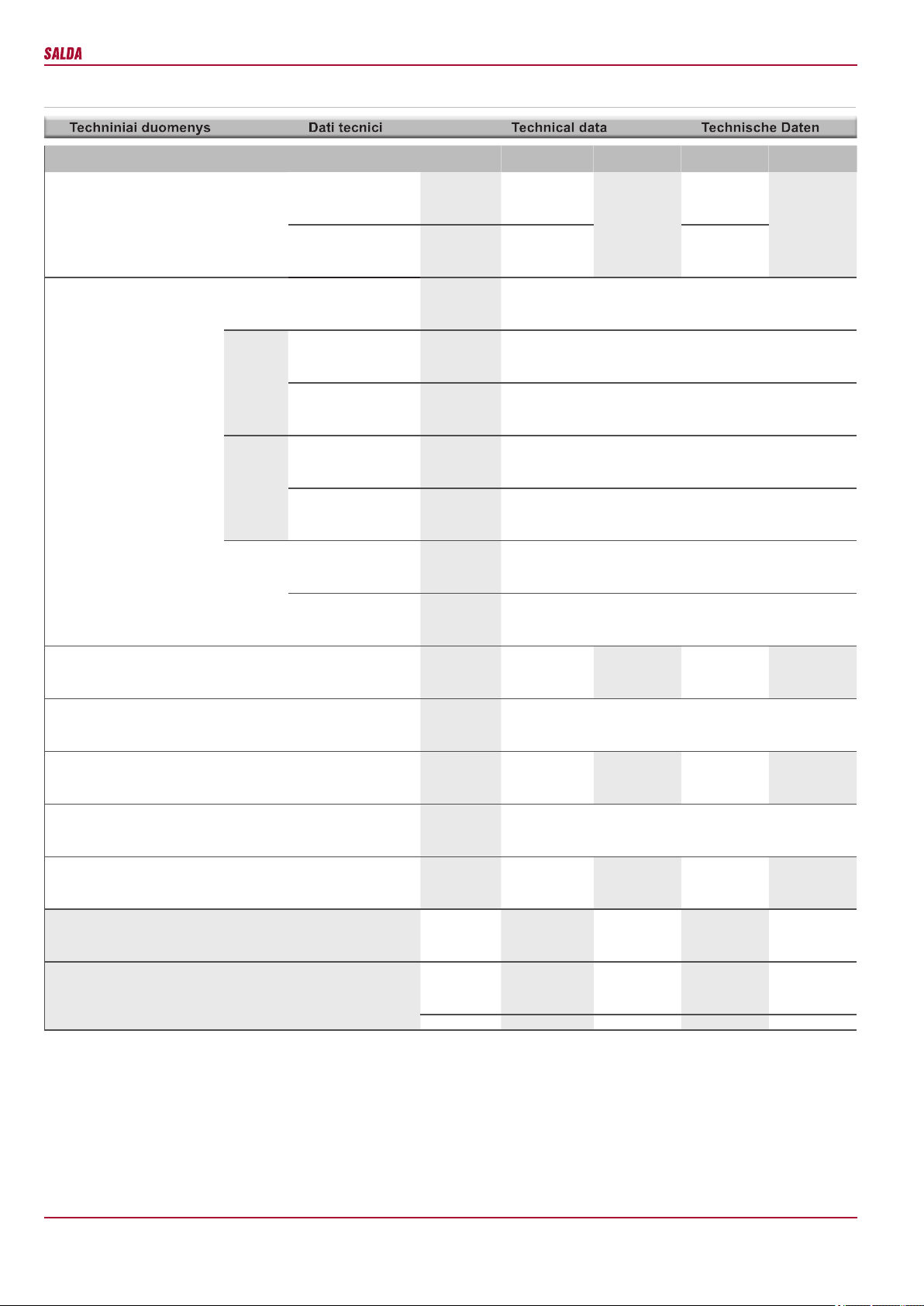
Tiekiamas oras
Immissione
Supply
Zuluft
- temperatūra min./maks.
- temperatura min./max.
- temperature min./max.
- Temperatur min./max. [°C] -3 / +40
Be pašildytuvo
con batteria elettrica di
preriscaldamento
Without preheater
Ohne Vorheizregister
- temperatūra min./maks.
- temperatura min./max.
- temperature min./max.
- Temperatur min./max. [°C] -40 / +40
Su pašildytuvu
senza batteria elettrica di
preriscaldamento
with preheater
Mit Vorheizregister
- maks. drėgmė
- umidità
- max. humidity
- max. Feuchtigkeit
[%] 90
Lent. 1
Таb. 1
Tab. 1
Tab. 1 Ištraukiamas oras
Estrazione
Extract
Abluft
- temperatūra min./maks.
- temperatura min./max.
- temperature min./max.
- Temperatur min./max.
[°C] +15 / +40
- maks. drėgmė
- umidità
- max. humidity
- max. Feuchtigkeit
[%] 60
It is recommended to use electrical pre-heater
if the supply air temperature is below -23 oC.
Required ambient temperatures must be from
+5 oC to +40 oC.
The air handling units installed outdoors shall be
started only when the following obligatory condi-
tions established by the manufacturer are met:
• Units that are stored at the site before instal-
lation shall be sealed using additional means in
order to prevent the accumulation of moisture
inside the unit.
• If the unit is installed and is not started for
ontinuous operation, it must be ensured that no
warm/humid air enters the unit through air ducts
and that no moisture condensates inside the unit.
• If the ventilation units stand idle for a long
time or are started infrequently, the system must
be blown down at the maximum capacity 1/24
h to dehumidify.
• Voltage to the automatics of the unit is installed
and connected; the system of water products is
lled with glycol/water.
In case of failure to comply with the require-
ments set out above, the manufacturer shall have
the right not to apply the warranty in respect of
the occurrence of moisture/water in damaged
components.
The unit can work at -40 ° C only with outdoor
air pre-heater, which must warmed outdoor air
up to -3 ° C temperature. Without outdoor air
pre-heater, the unit will work only to -3.5 ° C
when using the Toutside anti-frost algorithm or
the calculated freezing temperature if Klingb
anti-frost algorithm is used. The Klingb anti-
frost algorithm calculates the potential freezing
temperature of the heat exchanger according
room air temperature, room humidity and outdoor
air temperature.
The unit is temporarily stopped due to the risk
of freezing the heat exchanger or because of
the low supply air temperature, the unit starts up
itself when the freezing risk disappear. Factory
that every 3 hours the unit starts up for ~ 5 min.
at the highest speed and check didn’t disap-
peared heat exchanger frost risk. If the reasons
have disappeared, the unit will work normally
at the speed that was set before the frost risk.
If the reasons have not disappeared, the unit
after 5 min. is temporarily stopped until the next
inspection. If during the test the temperature of
the supply air falls below the set limit, the unit is
stopped after about 3 minutes.
The message on the screen disappears only
when the unit goes into normal mode.
Bei Außentemperaturen unter -23 °C ist es zu
emphehlen ein Vorheizrgeister zu benutzen.
Temperatur der Arbeitsumgebung muss im
Bereich von +5…+40 °C liegen.
Die im Freien betriebenen Lüftungseinrichtun-
gen werden nur dann eingeschaltet, wenn alle
obligatorischen, durch Hersteller angegebenen
Bedingungen gewährleistet sind. Die Bedin-
gungen sind:
• Die bevor Montage in Baustelle gelagerten
Einrichtungen sollen zusätzlich verdichtet
werden, um die Feuchtigkeitsansammlung in
Einrichtung zu vermeiden.
• Wird die Einrichtung montiert, doch instand
nicht gesetzt, so soll der Durchuss von warmer
bzw. feuchter Luft in Lüftungseinrichtungen
verhindert werden, um Kondensatansammlung
in Einrichtung zu vermeiden.
• Werden die Lüftungseinrichtungen nur selten
betrieben oder Betriebspausen ausgesetzt, so ist
das System einmal in 24 Stunden mit maximaler
Leistung zu belüften und zu trocknen.
• Die Steuerungselektronik der Lüftungsein-
richtung ist montiert und stromgespeist. Das
Wassersystem ist mit Mischung von Glykol und
Wasser befüllt.
Der Hersteller übernimmt keine Gewähr-
leistung, die im Folge der Nichtbeachtung
oben genannten Anweisungen und daraus
resultierenden Einrichtungsbeschädigungen
durch Feuchtigkeits-bzw. Wassereinwirkung
entstehen.
Das Gerät kann bis auf -40 ° C nur mit dem
Vorheizregister betrieben werden, die Außen-
lufttemperatur muss bis auf -3 ° C vorerwärmt
werden. Ohne Vorheizregister kann das Gerät
nur bis bis auf -3,5 ° C Aussentemperatur arbei-
ten, wenn Frostschutzstrategie nach Algorithmus
Toutside oder Frostschutzstrategie Klingb nach
berechnetem Frostpunkt verwedet wird. Klingb
Froststrategie berechnet das mögliche Einfrieren
des Wärmetauschers gemäß der Ablufttempe-
ratur aus dem Raum, Raumabluftfeuchte und
Aussenlufttemperatur.
Das Gerät wegen Frostgefahr und zu niedri-
gen Zulufttemperaturen wird vorübergehend
gestoppt. Das Gerät schaltet sich ein, wenn
die Voraussetzungen für das Einfrieren des
Wärmetauschers weg sind. Werkseinstellung
nach schaltet sich das Gerät jede 3 Stunden
für ca. 5 Minuten in höchster Stufe ein um zu
prüfen, ob die Voraussetzungen für Einfrieren
des Wärmetauschers weg sind.
Wenn die Voraussetuzngen für das Einfrieren
des Wärmetauschers weg sind, dann arbeitet
das Gerät weiter wie vorher eingestellt. Wenn
die Voraussetzngen für das Einfrieren des
Wärmetauschers nicht weg sind, dann wird das
Gerät nach 5 Minuten bis zur nächsten Überprü-
fung gestoppt. Wenn während der Prüfung die
Esant žemesnei tiekiamo oro temperatūrai
nei -23 °C rekomenduojama naudoti elektrinį
pašildytuvą.
Darbo aplinkos temperatūra privalo būti nuo
+5 iki +40 oC.
Lauke eksploatuojami vėdinimo įrenginiai pra-
dedami naudoti tik tada, kai užtikrinamos ga
mintojo nustatytos privalomos sąlygos:
• Įrenginiai, kurie prieš sumontuojant yra san-
dėliuojami objekte, turi būti užsandarinti papil-
domomis priemonėmis, kad įrenginio viduje
nesikauptų drėgmė.
• Jei įrenginys sumontuojamas ir nepalei-
džiamas pastoviai veikti, privaloma užtikrinti,
kad per ortakius į vėdinimo įrenginį nepatektų
šiltas/drėgnas oras ir drėgmė nesikondensuotų
įrenginyje.
• Ilgai neeksploatuojant ar retai jungiant vė-
dinimo įrenginius privaloma visu galingumu
1/24h prapūsti - džiovinti sistemą.
• turi būti instaliuota ir įjungta įtampa į agregato
automatiką, vandeninių gaminių sistema pripil-
dyta glikolio/vandens.
Nesilaikant šių reikalavimų gamintojas turi
teisę gedimo atveju netaikyti garantijos dėl
atsiradusios drėgmės/vandens sugadintuose
komponentuose.
Agregatas gali būti eksploatuojamas iki -40°C
tik su lauko oro pašildytuvu, kuris lauko oro
temperatūrą turi pašildyti iki -3°C. Be lauko oro
pašildytuvo agregatas veiks tik iki -3,5°C kai
naudojamas Toutside priešužšaliminės algori-
tmas arba pagal apskaičiuotą užšalimo tempe-
ratūrą jei naudojamas Klingb priešužšaliminės
algoritmas. Klingb priešužšaliminės algoritmas
apskaičiuoja galimą šilumokaičio užšalimo
temperatūrą pagal iš patalpos ištraukiamo oro
temperatūrą, pagal iš patalpos ištraukiamo oro
drėgnumą ir pagal lauko oro temperatūrą.
Agregatas laikinai sustabdomas dėl šilumo-
kaičio užšalimo rizikos arba dėl per žemos tie-
kiamo oro temperatūros, agregatas pasileidžia
pats, kai dings stabdymo priežastys. Gamy-
kliškai nustatyta, kad kas 3 val. agregatas pa-
sileidžia ~5 min. didžiausiu greičiu ir tikrina, ar
stabdymo priežastys nedingo. Jeigu priežastys
dingo, agregatas veikia nesustodamas tik jau
tuo greičiu, kuris buvo nustatytas prieš stabdy-
mą. Jeigu priežastys nedingo, agregatas po 5
min. stabdomas iki kito patikrinimo. Jeigu pati-
krinimo metu į patalpą tiekiamo oro temperatū-
ra nukrenta žemiau nustatytos ribos, agregatas
stabdomas po maždaug 3min.
Pranešimas ekrane dingsta tik tuomet, kai
agregatas pereina į normalų režimą.
È consentito collegare dispositivi esterni di ven-
tilazione solo dopo aver garantito le necessarie
condizioni imposte dal produttore:
• Dispositivi che, prima dell‘installazione, era-
no conservati nel magazzino, devono essere
ulteriormente sigillati per impedire l‘accumulo
dell‘umidità all‘interno del dispositivo.
• Se una volta installato il dispositivo non viene
usato costantemente, è necessario impedire la
penetrazione dell‘aria calda/umida attraverso le
condotte d‘aria e la formazione della condensa
all‘interno del dispositivo di ventilazione.
• le unità ventilanti vengono utilizzate saltua-
riamente, al momento del riavvio è necessario
che vengano fatte funzionare per un’ora alla
massima velocità al ne di evacuare eventuali
depositi di condensa.
• Alimentando la macchina l’elettronica viene
messa in tensione e se sono presenti batterie
idroniche queste devono essere alimentate con
acqua ed eventualmente acqua glicolata.
In caso di mancato adeguamento alle prescri-
zioni di cui sopra il produttore ha il diritto di an-
nullare la garanzia, qualora un guasto dell’unità
risulti causato dalla presenza di condensa sulla
parte elettronica della stessa.
L’unità può lavorare con temperatura dell’aria
esterna di -40° C soltanto con una batteria
elettrica antigelo che porti la temperatura no
a 3°C. In assenza di batteria antigelo sulla pre-
sa di aria esterna, l’unità può operare soltanto
con temperatura no a -3,5° C quando è attivo
il sistema antigelo basato sulla temperatura
esterna oppure quello basato sull’algoritmo
Klingenburg per il calcolo della temperatura
di formazione del ghiaccio. Questo algoritmo
calcola la temperatura presunta di formazione
del ghiaccio nello scambiatore basandosi sulla
temperatura ed U.R. dell’aria estratta e sulla
temperatura dell’aria esterna.
L’unità viene fermata momentaneamente quan-
do si presenta il rischio di gelo a causa della
temperatura di immissione troppo bassa e poi
viene riavviata quando il rischio di gelo viene
meno. Per vericare se tale rischio esista an-
cora o meno, ogni tre ore l’unità si avvia alla
massima velocità e opera per 5 minuti. Qualora
le condizioni siano tornate favorevoli, il recu-
peratore ricomincerà a funzionare al regime di
rotazione dei ventilatori impostato precedente-
mente dall’utente. Se, al contrario, le condizioni
non sono tornate favorevoli, l’unità si fermerà
nuovamente no al successivo ciclo di prova.
Se durante tale ciclo la temperatura dell’aria
immessa dovesse scendere sotto il limite im-
postato dalla fabbrica, l’unità verrebbe fermata
dopo circa 3 minuti.
Un messaggio che avverte della procedura an-
tigelo in atto appare sul pannello di comando
remoto e scompare soltanto quando il funzio-
namento torna ad essere quello normale.
7
RIS VE/VW EKO 3.0
[ lt ] [ it ] [ en ] [ de ]
- Maintenance and repair should only be per-
formed by experienced and trained sta󰀨.
- The fan should be inspected and cleaned if
needed at least once a year.
- Be sure the fan is disconnected from power
source before performing any maintenance
or repair.
- Proceed to maintenance and repair after any
rotation in the fan stopped.
- Observe sta󰀨 safety regulations during main-
tenance and repair.
- The motor is of heavy duty ball bearing con-
struction. The motor is completely sealed and
requires no lubrication for the life of the motor.
- Detach fan from the unit.
- Impeller should be specially checked for
buil-up material or dirt which may cause an
imbalance. Excessive imbalance can lead to ac-
celerated wear on motor bearings and vibration.
- Clean impeller and inside housing with mild
detergent, water and damp, soft cloth.
- Do not use high pressure cleaner, abrasives,
sharp instruments or caustic solvents that may
scratch or damage housing and impeller.
- Do not plunge impeller into any uid.
- Make sure, that impeller’s balance weights
are not moved.
- Make sure the impeller is not hindered.
- Mount the fan back into the unit. Replace
fan guards and connect the fan to power sup-
ply source.
- If after maintenance or repair the fan does not
start either thermal protection contact activates
automatically, contact the manufacturer.
- During the maintenance do not hold the fan by
the impeller, it might cause disbalance of impeller
or damage it. Hold the fan by the casing.
- Montage und Elektroarbeiten nur durch aus-
gebildetes und eingewiesenes Fachpersonal
und nach den jeweils zutre󰀨enden Vorschriften
ausführen.
- Die Anlage muss min. einmal pro Jahr geprüft
und gereinigt werden.
- Vor der Wartung oder Reparatur sicherstellen,
dass die Anlage vom Stromnetz getrennt ist.
- Arbeiten dürfen nur bei abgeschaltetem und
mechanischem Stillstand des Laufrades sowie
nach Abkühlung der Heizung vorgenommen
werden! Gegen Wiedereinschalten sichern!
- Arbeitssicherheitsregelungen bei der tech-
nischen Bedienung beachten.
- In der Motorkonstruktion sind hochwertige
Lager eingebaut. Die Lager sind eingepresst
und erfordern keine Schmierung.
- Ventilator von der Anlage abschalten.
- Die Flügel vom Ventilator auf Ablagerungen
und Staub prüfen, starke Verschmutzung kann
zu Unwucht führen. Die Unwucht verursacht
eine Vibration und schnelleren Lagerverschleiß.
- Flügel und Gehäuse mit einem sanften Rei-
nigungsmittel abwaschen, keine aggressiven
Putzmittel verwenden die das Material angreifen
könnten. Flügel und Gehäuse danach mit viel
Wasser gründlich reinigen, keine Hochdruck-
anlage, Putzmittel, scharfes Werkzeug oder
aggressive Sto󰀨e verwenden, die zu Kratzer
und Beschädigungen führen könnten.
- Beim Reinigen der Flügel Motor vor Feuch-
tigkeit und Nässe schützen.
- Prüfen, dass die Wuchtgewichte am Flügel
nicht verschoben werden.
- Flügel darf nicht am Gehäuse streifen.
- Montieren des Ventilators wieder in die An-
lage. Anschließen die Anlage ans Stromnetz.
- Sollte sich nach Wartung der Anlage der
Ventilator nicht mehr einschalten lassen oder
der Thermokontaktschutz auslösen, an den
Hersteller wenden.
- Während der Wartung den Ventilator, der
herausgenommen/ eingelegt wird, nicht an
Laufradügel halten, weil es zu Unwucht/ Be-
schädigung des Laufrades führen kann. Nur am
Ventilatorgehäuse halten.
Unplug unit from mains rst and wait for 2
minutes (till fans fully stop) before opening
the covers.
Bevor die Gerätetüren geö󰀨net werden dürfen,
Gerät elektrisch vom Versorgungsnetz trennen
und etwa 2 Min. warten, bis die Ventilatoren
völlig stehen bleiben.
Prieš atidarydami agregato duris būtinai atjun-
kite elektros srovę ir palaukite, kol pilnai nustos
suktis ventiliatoriai (apie 2 min.).
Prima di aprire lo sportello del dispositivo
staccare l’alimentatore della corrente e aspettare
che la rotazione dei ventilatori si arresti comple-
tamente (2 min. circa).
Dirt increases air resistance in the lter, there-
fore less air is supplied into the premises.
- It is advisable to change the lters every 3-4
months, or in accordance with the readings of
lter contamination sensor. (Sensor PS 600 is
integrated in the unit).
Verunreinigte Filter erhöhen die Druckverluste,
d.h. ein geringeres Luftvolumen gelangt in die
Räume.
- Die Filter werden ca. alle 3 Monate bzw. je
nach Signal der Filterüberwachung ersetzt. (Der
Fühler PS 600 ist im Aggregat integriert).
Užsiteršę ltrai, didina oro pasipriešinimą, dėl
to sumažėja į patalpas paduodamo oro kiekis.
- Filtrus patartina keisti kas 3-4 mėnesius arba
pagal ltro užterštumo jutiklio parodymus (juti-
kliai PS 600 integruoti į agregatą).
Užsiteršę ltrai, didina oro pasipriešinimą, dėl
to sumažėja į patalpas paduodamo oro kiekis.
- Filtrus patartina keisti kas 3-4 mėnesius arba
pagal ltro užterštumo jutiklio parodymus (jutiklis
PS 600 integruotas į agregatą).
- Aptarnavimo darbus turėtų atlikti tik patyrę ir
apmokyti darbuotojai.
- Ventiliatorius turi būti apžiūrimas ir valomas
mažiausiai 1 kartą per metus.
- Prieš pradedant aptarnavimo ar remonto
darbus įsitikinkite, ar įrenginys atjungtas nuo
elektros tinklo.
- Aptarnavimo darbus pradėkite tik sustojus
bet kokiam judėjimui ventiliatoriuje.
- Vykdydami techninio aptarnavimo darbus lai-
kykitės visų darbo saugos taisyklių.
- Variklio konstrukcijoje panaudoti aukšto na-
šumo guoliai. Jie yra užpresuoti ir nereikalauja
jokio tepimo per visą variklio tarnavimo laiką.
- Atjunkite ventiliatorių nuo įrenginio.
- Būtina kruopščiai apžiūrėti ventiliatoriaus
sparnuotę, ar nesusidarė dulkių ir kitokių me-
džiagų apnašos, galinčios išbalansuoti spar-
nuotę. Išbalansavimas sukelia vibraciją ir grei-
tesnį variklio guolių susidėvėjimą.
- Nuvalykite sparnuotę ir korpuso vidų švelniu,
netirpdančiu bei korozijos neskatinančiu plovi-
kliu ir vandeniu.
- Valydami sparnuotę nenaudokite aukšto
slėgio įrenginių, šveitiklių, aštrių įrankių arba
agresyvių tirpiklių, galinčių įbrėžti ar pažeisti
sparnuotę.
- Valydami sparnuotę nepanardinkite variklo į
skystį.
- Įsitikinkite, ar sparnuotės balansiniai svars-
čiai savo vietose.
- Įsitikinkite, ar sparnuotė nekliūna už korpuso.
- Sumontuokite ventiliatorių atgal į įrenginį. Pri-
junkite prie elektros tinklo.
- Jei po aptarnavimo darbų ventiliatorius neįsi-
jungia, arba savaime įsijungia termokontaktinė
apsauga - kreipkitės į gamintoją.
- Aptarnavimo metu, išimant/įdedant ventiliato-
rių nelaikyte jo už sparnuotės menčių. Tai gali
išbalansuoti ar sugadinti sparnuotę. Laikykite
tik už ventiliatoriaus korpuso.
- Solo personale esperto e qualificato può
e󰀨ettuare lavori di manutenzione straordinaria.
- Il ventilatore deve essere ispezionato visiva-
mente e pulito almeno una volta all’anno.
- Prima di e󰀨ettuare i lavori di manutenzione e
di riparazione assicurarsi che il dispositivo sia
scollegato dalla rete elettrica.
- E󰀨ettuare i lavori di manutenzione solo quan-
do tutte le parti del ventilatore si sono fermate.
- Durante i lavori di manutenzione tecnica,
attenersi alle opportune disposizioni di sicurezza
sul lavoro.
- Nel corpo del motore sono inseriti i cuscinetti
ad alta e󰀩cienza. Sono sigillati e non richiedono
alcuna lubricazione per tutta la durata della
vita del motore.
- Scollegare il ventilatore dall’unità.
- È necessario ispezionare accuratamente la
ventola del ventilatore, controllando altre che
non si sia accumulata della polvere o aitre
sostanze che potrebbero sbilanciare la ventola.
Lo sbilanciamento provoca vibrazioni e accelera
l’usura dei cuscinetti del motore.
- Pulire la ventola e la parte interna del corpo
con acqua e detergente delicato non corrosivo.
- Per pulire la ventola non utilizzare apparecchi
ad altapressione, prodotti abrasivi, strumenti
appuntiti e solventi aggressivi che possono
gra󰀩are o danneggiare la ventola.
- Durante la pulizia della ventola non immergere
motore nell’acqua.
- Assicurarsi che i pesi di bilanciamento della
ventola siano nella loro sede.
- Assicurarsi che la ventola non sfreghi contro
il corpo dell’unità.
- Reinserire il ventilatore nel dispositivo. Colle-
gare alla rete elettrica.
- Se dopo la manutenzione il ventilatore non si
accende oppure il termocontatto di protezione
entra in azione, contattare il produttore.
- Durante i lavori di manutenzione, durante la
rimozione e il riposizionamento del ventilatore
non prenderlo per le pale della ventola, questo
potrebbe provocare uno sbilanciamento oppure
un guasto della ventola stessa. Prendere solo
per il corpo del ventilatore.
Zulufttemperatur unter eingestellter Temperatur
runterfällt, dann wird das Gerät nach 3 Minuten
gestoppt.
Anzeige auf dem Bedienteil nur dann ver-
schwindet, wenn das Gerät in Normalbetrieb
zurückkommt.
8
RIS VE/VW EKO 3.0
[ lt ] [ it ] [ en ] [ de ]
La batteria elettrica non richiede alcuna manu-
tenzione particolare. È solo necessario sostituire
i ltri come descritto in precedenza.
La batteria è dotato di 2 protezioni termiche:
una protezione con reset automatico che si
attiva a +50 ºC e una con reset manuale che si
avvia a +100 ºC.
Nel caso di scatto della protezione con reset
manuale bisogna scollegare il dispositivo dalla
fonte di alimentazione. Aspettare che si ra󰀨red-
dino gli elementi riscaldanti e si fermi la rotazione
dei ventilatori. Individuare le cause del guasto e
risolverle. Premere il tasto “reset”e riavviare il
dispositivo. Solo il personale qualicato può
ndividuare la causa del guasto.
Se necessario, la batteria elettrica può essere
rimossa. Per farlo, scollegare il connettore
elettrico della batteria e rimuoverla.
(Fig. a-b).
Electrical heater does not need to be serviced
additionally. It is compulsory to change lters as
described above.
Heaters have 2 thermal protections: auto-
matically self-resetting, which activates at +50°C
and the manually restored, which activates at
+100°C.
After the activation of the manually restored
protection, the unit must be disconnected from
the power supply. Wait until the heating elements
cool down and the fans stop rotating. After iden-
tifying and removing the reason of failure, to start
the unit, press the “reset” button. The failure can
be identied only by a qualied professional.
If necessary, the electrical heater can be
removed. Disconnect the electrical connector
from the heater and remove the heater (Pic. a-b).
Das Elektro-Heizregister bedarf keiner zusätz-
lichen Wartung. Es sind nur die Filter rechtzeitig
zu wechseln, wie oben aufgeführt.
Heizregister verfügen über 2 Wärmeschutz-
vorrichtungen: die mit einer automatischen
Rückstellung, die bei +50 ºC anspricht; die mit
einer manuellen Rückstellung, die bei +100 ºC
anspricht.
Bei Ansprechen der Schutzvorrichtung mit
manueller Rückstellung ist das Gerät vom
Stromnetz zu trennen. Abwarten, bis die Heiz-
körper sich abgekühlt haben und die Ventilatoren
zum Stillstand gekommen sind. Nachdem das
Problem identiziert und gelöst ist, die „reset“
Taste drücken und das Gerät wieder in Betrieb
nehmen. Ausfall kann nur durch Fachperso-
nal festgestellt werden. Bei Bedarf kann das
Elektro-Heizregister herausgenommen werden.
Dazu den Stromanschluss am Heizregister
trennen und das Heizregister herausziehen
(Abb. a-b).
Elektrinis šildytuvas papildomo aptarnavimo
nereikalauja. Būtina tik laiku keisti ltrus, kaip
nurodyta auksčiau.
Šildytuvai turi 2 šilumines apsaugas: automa-
tiškai atsistatančią, kuri suveikia prie +50 ºC;
ir rankiniu būdu atsatomą, kuri suveikia prie
+100 ºC.
Suveikus rankiniu būdu atstatomai apsaugai
reikia atjungti įrengini nuo maitinimo šaltinio.
Palaukti kol atvės kaitinimo elementai ir nustos
suktis venatiliatoriai. Nustačius gedimo priežas-
tį, reikia ją pašalinti. Paspausti “reset” mygtuką
ir paleisti įrenginį. Nustatyti gedimą gali tik
kvalikuotas darbuotojas.
Esant būtinybei elektrinį šildytuvą galima išim-
ti. Reikia atjungti elektrinę jungtį nuo šildytuvo ir
šildytuvą ištraukti (Pav. a-b).
Prieš pradedant aptarnavimo ar remonto dar-
bus įsitikinkite, ar įrenginys atjungtas nuo elek-
tros tinklo.
Aptarnavimo darbus pradėkite tik sustojus bet
kokiam judėjimui ventiliatoriuose.
Šilumokaitis valomas kartą metuose.
Atsargiai išėmę šilumokaičio kasetę, panar-
dinkite ją į talpą su muiluotu vandeniu (nenau-
dokite sodos). Po to kasetę nuplaukite nestipria
karšto vandens srove (per stipri srovė gali su-
lankstyti jos plokšteles). Šilumokaitį į agregatą
galima statyti tik pilnai jam išdžiūvus.
Prima di e󰀨ettuare i lavori di manutenzione e
di riparazione assicurarsi che il dispositivo sia
scollegato dalla rete elettrica.
E󰀨ettuare i lavori di manutenzione solo quando
tutte le parti dei ventilatori si sono fermate.
La pulizia dello scambiatore di calore viene
e󰀨ettuata una volta all’anno.
Estrarre delicatamente la cassetta dallo
scambiatore, immergerla in un recipiente con
acqua saponata (non usare bicarbonato di
sodio). Lavare la cassetta sotto un debole getto
d’acqua calda (un getto d’acqua troppo forte può
deformare le piastre). Reinserire lo scambiatore
di calore nel dispositivo solo quando sarà com-
pletamente asciutto.
Be sure the unit is disconnected from power
source before performing any maintenance
or repair.
Proceed to maintenance and repair after any
rotation in the fan stopped.
Clean it once a year.
Firstly take out heat exchanger cassette care-
fully. Submerge it into a bath and wash with warm
soapy water (do not use soda). Then rinse it with
hot water and let it to dry up completely.
Wird einmal jährlich gereinigt.
Einmal jährlich reinigen.
Zuerst vorsichtig die Kassette des Wärme-
tauschers herausziehen. In eine Wanne mit
warmem Seifenwasser tauchen und reinigen
(kein Sodawasser verwenden).
Danach heißem Wasser durchspülen und
trocknen lassen.
9
RIS VE/VW EKO 3.0
[ lt ] [ it ] [ en ] [ de ]
Įmonė pasilieka teisę keisti techninius
duomenis
Subject to technical modication Änderungen in Konstruktion und Design sind
vorbehalten
Il produttore si riserva il diritto di apportare
modiche ai dati tecnici
Thermal e󰀩ciency of RIS 700VE/VW EKO 3.0 was measured at 700 m3/h (indoor conditions +20O/60%; outdoor conditions -7O/90%).
Thermal e󰀩ciency of RIS 1200VE/VW EKO 3.0 was measured at 1200 m3/h (indoor conditions +20O/60%; outdoor conditions -7O/90%).
RIS 700VE EKO 3.0 RIS 700VW EKO
3.0
RIS 1200VE EKO
3.0
RIS 1200VW
EKO 3.0
Šildytuvas
Batteria post riscaldamento
Heizregister
Heater
- fazė/įtampa
- fase/tensione
- phase/voltage
- Phase/Spannung
[50 Hz/VAC] ~1,230
AVS 250
~1,230
AVS 315,
AVA 315
- naudojama galia
- potenza assorbita
- power consumption
- Leistungsaufnahme
[kW] 1,2 2,0
Ventiliatoriai
Ventilatori
Fans
Ventilatoren
- fazė/įtampa
- fase/tensione
- phase/voltage
- Phase/Spannung
[50 Hz/VAC] ~1,230 ~1,230
šalinimo
di estra-
zione
exhaust
abluft
- galia/srovė
- potenza/corrente
- power/current
- Nennleistung/Nennstrom
[kW/A] 0,218 / 1,64 0,435 / 2,9
- apsisukimai
- giri
- speed
- Drehzahl
[min-1]3380 3400
tiekimo
di immis-
sione
supply
zuluft
- galia/srovė
- potenza/corrente
- power/current
- Nennleistung/Nennstrom
[kW/A] 0,23 / 1,66 0,430 / 2,95
- apsisukimai
- giri
- speed
- Drehzahl
[min-1]3380 3400
- valdymo signalas
- segnale di controllo
- control input
- Steuerungsignal
[VDC] 0-10 0-10
- apsaugos klasė
- classe di protezione
- protection class
- Schutzart
IP44 IP54
Bendra naudojama galia
Potenza assorbita generale
Total power consumption
Total Leistungsaufnahme
- galia/srovė
- potenza/corrente
- power/current
- Nennleistung/Nennstrom
[kW/A] 1,65 / 8,51 0,45 / 3,30 0,98
/ 6,31 2,87 / 14,49 0,87 / 5,89
Valdymo automatika sumontuota
Controllo automatico integrato
Automatic control integrated
Integriertes Steuerungsystem
+ +
Šiluminis našumas
Rendimento termico
Thermal e󰀩ciency
Thermischer Wirkungsgrad
90% 90% 90% 90%
Sienelių izoliacija
Isolamento dell’involucroe
Insulation of walls
Isolation der Wände
[mm] 30 50
Svoris
Peso
Weight
Gewicht
[kg] 112,5 112 290,0 290,0 290,0
Maitinimo laido skerspjūvis
Sezione del cavo di alimentazione
Cross-section of the power supply cable
Querschnitt Netzkabel
[mm²] 3x1,5 3x1,5 3x2,5 3x1,5
Apsaugos įrenginys*
Dispositivo di protezione*Circuit
breaker*
Sicherungsautomat*
Poliai
Poli
Poles
Polzahl
1 1 1 1
I [A] B10 B10 B20 B10
10
RIS VE/VW EKO 3.0
[ lt ] [ it ] [ en ] [ de ]
Įmonė pasilieka teisę keisti techninius
duomenis
Subject to technical modication Änderungen in Konstruktion und Design sind
vorbehalten
Il produttore si riserva il diritto di apportare
modiche ai dati tecnici
Thermal e󰀩ciency of RIS 1900VE/VW EKO 3.0 was measured at 1900 m3/h (indoor conditions +20O/60%; outdoor conditions -7O/90%).
Thermal e󰀩ciency of RIS 2200VE/VW EKO 3.0 was measured at 2200 m3/h (indoor conditions +20O/60%; outdoor conditions -7O/90%).
RIS 1900VE EKO
3.0
RIS 1900VW
EKO 3.0
RIS 2200VE EKO
3.0
RIS 2200VW
EKO 3.0
Šildytuvas
Batteria post riscaldamento
Heizregister
Heater
- fazė/įtampa
- fase/tensione
- phase/voltage
- Phase/Spannung
[50 Hz/VAC] ~1,230
AVS 400,
AVA 400,
Comfort Box 400
~1,230
AVS 400,
AVA 400,
Comfort Box 400
- naudojama galia
- potenza assorbita
- power consumption
- Leistungsaufnahme
[kW] 3,0 3,0
Ventiliatoriai
Ventilatori
Fans
Ventilatoren
- fazė/įtampa
- fase/tensione
- phase/voltage
- Phase/Spannung
[50 Hz/VAC] ~1,230 ~1,230
šalinimo
di estra-
zione
exhaust
abluft
- galia/srovė
- potenza/corrente
- power/current
- Nennleistung/Nennstrom
[kW/A] 0,49 / 3,2 0,715 / 3,2
- apsisukimai
- giri
- speed
- Drehzahl
[min-1]2540 2800
tiekimo
di immis-
sione
supply
zuluft
- galia/srovė
- potenza/corrente
- power/current
- Nennleistung/Nennstrom
[kW/A] 0,49 / 3,1 0,715 / 3,1
- apsisukimai
- giri
- speed
- Drehzahl
[min-1]2540 2800
- valdymo signalas
- segnale di controllo
- control input
- Steuerungsignal
[VDC] 0-10 0-10
- apsaugos klasė
- classe di protezione
- protection class
- Schutzart
IP54 IP54
Bendra naudojama galia
Potenza assorbita generale
Total power consumption
Total Leistungsaufnahme
- galia/srovė
- potenza/corrente
- power/current
- Nennleistung/Nennstrom
[kW/A] 3,98 / 19,32 0,98 / 6,31 4,43 / 19,32 1,43 / 6,31
Valdymo automatika sumontuota
Controllo automatico integrato
Automatic control integrated
Integriertes Steuerungsystem
+ +
Šiluminis našumas
Rendimento termico
Thermal e󰀩ciency
Thermischer Wirkungsgrad
90% 90% 90% 90%
Sienelių izoliacija
Isolamento dell’involucroe
Insulation of walls
Isolation der Wände
[mm] 50 50
Svoris
Peso
Weight
Gewicht
[kg] 290,0 290,0 290,0 290,0
Maitinimo laido skerspjūvis
Sezione del cavo di alimentazione
Cross-section of the power supply cable
Querschnitt Netzkabel
[mm²] 3x2,5 3x1,5 3x2,5 3x1,5
Apsaugos įrenginys*
Dispositivo di protezione*Circuit
breaker*
Sicherungsautomat*
Poliai
Poli
Poles
Polzahl
1 1 1 1
I [A] B25 B10 B25 B10