4B+ Security Upgrade Kit – 3596
Installation Instructions for Vertical Mailboxes – Model 3507
U.S.P.S. Approved
Installation instructions for Salsbury Industries 7-Door Model 3507 vertical mailbox security upgrade kit.
It is recommended that the installation instructions be read completely prior to beginning work.
Kit Contents Drill two 1/8” diameter holes in the compartment assembly frame
through the two holes in the top of the Arrow Lock guard. Install the
#8 x 3/8” self-tapping screws through the guard holes into the frame
holes.
(If a smaller unit than the 7-door model 3507 is being upgraded, see
the appropriate instruction sheet and discard parts not needed.)
(4) Top Security Brackets
Modify Compartment Assembly Rear Wall
(1) Arrow Lock Guard (1) Arrow Lock Catch
(3) Templates (#1, #2 and #3) Installation Instructions Using Template #1 provided, follow template instructions to cut five
notches in the compartment assembly rear wall. See Illustration 3 for
dimensions of notches. Fold notch flaps to outside. See Illustration
4 for the final appearance of the compartment assembly.
Hardware Bag (4) 3/16”x7/16” blind rivets
(10) #8x3/8” self-tapping screws
(2) #10-32x1-1/4” screws
(2) #10-32 locknuts
Removing Old Arrow Lock Catch
Tools Required Turn the outer enclosure upside down and rest it on a table as shown
in Illustration 5. Using the chisel or 1/8” diameter drill bit, remove two
rivets and old Arrow Lock catch and discard.
Hammer Chisel
Center Punch Wood Block (2x4 x 6” long)
Phillips Screwdriver Blind Rivet Gun
Installing Top Security Brackets into Outer Enclosure
Utility Knife Drill Motor
Pencil 1/8” diameter Drill Bit Using the Template #2 provided, follow template instructions to install
four top security brackets. See Illustration 6.
Tin Snips 1/4” diameter Drill Bit
Masking Tape 7/32” diameter Drill Bit
Installing New Arrow Lock Catch
3/8” Open-end Wrench
Turn the outer enclosure over so it is right side up. Using Template
#3 provided, follow the template instructions to install the new Arrow
Lock catch. See Illustration 7 for catch holes location. See
Illustration 8 for the final appearance of the outer enclosure.
Disassembly and Removal from Wall
The postal delivery person must open the compartment assembly to
provide access for installing the security kit. Remove the
compartment assembly from the outer enclosure by tilting the
compartment assembly out and lifting it up to clear the lower edge of
the opening in the outer enclosure. Remove the outer enclosure
from the wall by removing the screws that secure it to the wall.
Reinstall in Wall
Reinstall outer enclosure in wall. Reinstall compartment assembly
into outer enclosure. Ensure that compartment assembly opens,
closes, and locks properly.
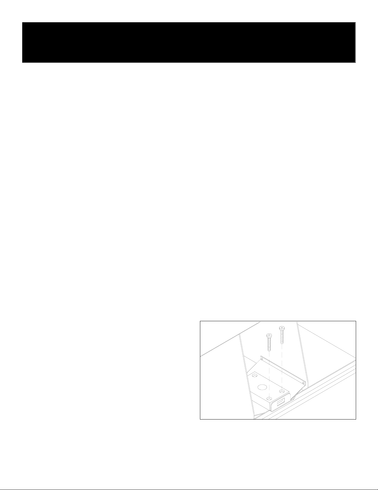
Installing Arrow Lock Guard on USPS Arrow Lock
Illustration 1 – Remove Screws
Lay the compartment assembly face down on a table. Remove the
top two screws from the USPS Arrow Lock as shown in Illustration 1.
Discard these screws. Remove the lock from the lock-mounting
bracket.
Stand the compartment assembly upright on a table. Open the door
that covers the USPS Arrow Lock. Using the drill motor and the 1/4”
diameter drill bit, drill out the two tapped holes from which the lock
mounting screws were removed.
Insert the two #10-32x1-1/4” pan head screws provided into the holes
from the front of the bracket, reinstall the lock at the rear of the
bracket, add the lock guard provided as shown in Illustration 2, and
attach the #10-32 lock nuts provided to the back of the screws.
Holding the #10-32 locknuts with the 3/8” wrench, tighten the Arrow
lock screws with the Phillips screwdriver.


