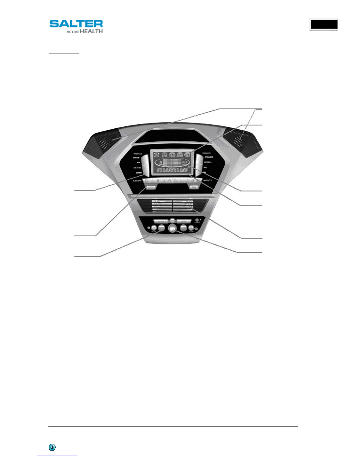
Salter PT-298 User manual

OWNER’S MANUAL V. 1 ENGLISH
PT-298 STR TREADMILL
This man al is available at www.salter.es
1
ENGLISH
PT-298 CINTA DE CORRER STR
STR TREADMILL
MANUAL DEL USUARIO
OWNER’S MANUAL
ESPAÑOL
ENGLISH

OWNER’S MANUAL V. 1 ENGLISH
PT-298 STR TREADMILL
This man al is available at www.salter.es
2
ENGLISH
1.
SAFET INSTRUCTIONS
WARNING: To reduce the risk of serious injury, read the following safety instructions before using the equipment.
1. Read all warnings posted on the eq ipment.
2. Read this Owner's Man al and follow it caref lly before sing the eq ipment. Make s re that it is properly
assembled and tightened before se.
3. We recommend that two people be available for assembly of this prod ct.
4. Keep children and pets away from the eq ipment. Do not allow children and pets to se or play on the
eq ipment. Always keep children and pets away from the eq ipment when it is in se.
5. It is recommended that yo place this exercise eq ipment on an eq ipment mat.
6. Set p and operate the eq ipment on a solid level s rface. Do not position the eq ipment on loose r gs or
neven s rfaces.
7. Inspect the eq ipment for worn or loose components prior to each se.
8. Tighten / replace any loose or worn components prior to sing the eq ipment.
9. Cons lt a physician prior to commencing an exercise program. If, at any time d ring exercise, yo feel faint,
dizzy, or experience pain, stop and cons lt yo r physician.
10. Follow yo r physician's recommendations in developing yo r own personal fitness program.
11. Always choose the worko t which best fits yo r physical strength and flexibility level. Know yo r limits and train
within them. Always se common sense when exercising.
12. Before sing this prod ct, please cons lt yo r personal physician for a complete physical examination.
13. Do not wear loose or dangling clothing while sing the eq ipment.
14. Never exercise in bare feet or socks; always wear correct footwear, s ch as r nning, walking, or cross-training
shoes.
15. Be caref l to maintain yo r balance while sing, mo nting, dismo nting, or assembling the eq ipment loss of
balance may res lt in a fall and serio s bodily inj ry.
16. Keep both feet firmly and sec rely on the Foot Pedals while exercising.
17. The eq ipment sho ld not be sed by persons weighing over 120 kg.
18. The eq ipment sho ld be sed by only one person at a time.
19. The eq ipment is for semi-commercial, light-commercial and home sage.
20. Maintenance: Replace the defective components immediately and / or keep the eq ipment o t of se ntil
repair the eq ipment completely.
21. Make s re that adeq ate space is available for access to and passage aro nd the eq ipment; keep at least a
distance of 1 meter from any obstr ction object while sing the machine
WARNING: Before starting any exercise or conditioning program yo sho ld cons lt with yo r personal physician to
see if yo req ire a complete physical exam. This is especially important if yo are over the age of 35, have never
exercised before, are pregnant, or s ffer from any illness.

OWNER’S MANUAL V. 1 ENGLISH
PT-298 STR TREADMILL
This man al is available at www.salter.es
3
ENGLISH
2. TOOLS KIT
3. ASSEMBL INSTRUCTIONS
STEP 1
Take o t the treadmill from the carton and lay it aside on the smooth gro nd.
STEP 2
1. Take the Left and Right pright t bes (part n mbers 5 & 4) and slide the pright covers (99 & 100 right) onto
the t bes (observe the cover orientation is correct). Connect the Middle Console Cable (38) that exits from the
bottom of the right pright t be with the lower Console Cable (39). Insert the Left and Right (5 & 4) Uprights
into the Left and Right Receiving T bes (holes are on the o tside of the t bes). Be caref l not to pinch the wire
when installing the pright.
NOTE: Partially tighten all bolts in this Step. This will allow for easier console assembly.
2. Attach the t bes with three B tton Head Socket Bolts (93) from each side and two B tton Head Socket Bolts
(93) and two C rved Washers (94) from the front. Partially tighten sing the Combination M5 Allen Wrench &
Phillips Head Screw Driver (96).
n m.97. M6 Allen
Wrench
n m.
33
.
Safety Key
n m.96. Combination M5 Allen
Wrench & Phillips Head Screw Driver
n m.
122
.
Phillips Head
n m.
58
. Deck/Bel
t
L bricant

OWNER’S MANUAL V. 1 ENGLISH
PT-298 STR TREADMILL
This man al is available at www.salter.es
4
ENGLISH
HARDWARE
n m.93. 5/16” x 15mm
B tton Head Socket Bolt
(8 pcs)
n m.94. 5/16” x 19 x 1.5T
C rved Washer (2 pcs)

OWNER’S MANUAL V. 1 ENGLISH
PT-298 STR TREADMILL
This man al is available at www.salter.es
5
ENGLISH
STEP 3
1. Connect the Speed Adj stment Switch Cable (128) to the Speed Cable (Upper) (126). Connect the Incline
Adj stment Switch Cable (129) to the Incline Cable (Upper)(127). Connect the Comp ter Cable (Middle) (37) to
the Comp ter Cable (Upper) (38).
2. Insert Console Assembly (40) into right and left Uprights (4) and (5) and sec re with fo r B tton Head Socket
Bolts (90) and fo r Split Washers (82) sing the M6 Allen Wrench (97). Now go back and completely tighten
the 8 bolts (93) inserted in Step 1 that join the pright t bes (4 & 5) to the main frame.
HARDWARE
n m.82. 3/8” x 2.0T
Split Washer (4 pcs)
n m.90. 3/8” x 1-3/4”
B tton Head Socket Bolt
(4 pcs)

OWNER’S MANUAL V. 1 ENGLISH
PT-298 STR TREADMILL
This man al is available at www.salter.es
6
ENGLISH
STEP 4
Attach the lower half of the bottle holder (Right - 100) and (Left - 99) to the right and left Uprights (4) and (5) and
Console S pport(6) with ten Sheet Metal Screws (89) sing the Phillips Head Screw Driver (122).
HARDWARE
n m.89. 3.5 x 12mm
Sheet Metal Screw (10 pcs)

OWNER’S MANUAL V. 1 ENGLISH
PT-298 STR TREADMILL
This man al is available at www.salter.es
7
ENGLISH
4. OPERATION INSTRUCTIONS
Do not attempt to move the nit nless it is in the folded and locked position. Be s re the power cord is sec red to
avoid possible damage. Use both handrails to move the nit to the desired position.
4.1 TO FOLD THE TREADMILL
Make certain the treadmill is at minim m incline. Lift the treadmill
r nning deck ntil it is sec red by the locking telescoping t be assembly
in center back of base.
4.2 TO UNFOLD THE TREADMILL
Apply slight forward press re* on the treadmill r nning deck with one
hand. P ll down on the nlocking lever and slowly lower the r nning
deck to the floor. The deck will lower nassisted when it reaches abo t
waist high.
*At the rear roller area to relieve press re on the locking system.
4.3 TRANSPORT
The treadmill is eq ipped with fo r transport wheels that are engaged
when the treadmill is folded. After folding simply roll the treadmill away.
4.4 HANDRAIL ADJUSTMENTS
The treadmill allows yo to make speed and incline changes on the side handrails. Yo
can also choose to t rn these off if yo freq ently hold on to these rails. This is
achieved by pressing the disable b tton on the right side of the lower portion of the
console.
4.5 QUICK SPEED & INCLINE BUTTONS
Yo are able to set yo r speed and incline settings q ickly by sing the q ick keys on
the console. J st press either Speed or Incline, then select either 1 or 2 digits and the
treadmill will a tomatically adj st to that val e. This saves time beca se yo don’t have to press and hold or hold a
b tton down ntil reaching the desired val e. The maxim m val e yo may inp t for speed is 9.9 km/h and incline
9.5%.
Examples:
Press the Q ick Incline b tton, then 1, 0 = Incline Level 1.0
Press the Q ick Incline b tton, then 3, 5 = Incline Level 3.5
Press the Q ick Speed b tton, then 8, 0 = 8.0 km/h
Press the Q ick Speed b tton, then 0, 8 = 0.8 km/h

OWNER’S MANUAL V. 1 ENGLISH
PT-298 STR TREADMILL
This man al is available at www.salter.es
8
ENGLISH
4.6 CONSOLE
The console will display Pace, Calories b rned, Time (elapsed or co ntdown), Distance travelled, P lse, Speed,
Incline, Program Name, n m. of Laps completed, and Segment Time. There is also a Speed & Incline profile graph
that lets yo see how hard yo have worked and how challenging the pcoming segments will be.
5. CONSOLE INSTRUCTIONS
5.1 GETTING STARTED
Power the treadmill on by pl gging it into an appropriate wall o tlet, then t rn on the power switch located at the
front of the treadmill below the motor cover. Ens re that the safety key is installed, as the treadmill will not power
on witho t it.
When the power is t rned on, all the lights on the display will light for a short time. Then the Time and Distance
windows will display Odometer readings for a short time. The Time window will show how many ho rs the treadmill
has been in se and the Distance window will show how many kilometers the treadmill has gone. Then a message in
the message center will show the c rrent software version. The treadmill will then enter idle mode, which is the
starting point for operation.
5.1.1 QUICK-START/MANUAL OPERATION
STEP 1: Press and release the Start key to wake display p (if not already on).
Note: Installing the tether key will also wake up the console.
STEP 2: Press and release the Start key to begin belt movement, at 1 km/h, then adj st to the desired speed sing
the + / - or Fast/Slow keys (console or hand rail). Yo may also se the q ick speed key, then 0 thro gh 9 to adj st
the speed.
STEP 3: To slow the tread-belt press and hold the v key (console or hand rail) to the desired speed. Yo may also
press the q ick speed adj st keys, 0 thro gh 9.
PROGRAM BUTTONS
(Man al, Hill, Fat B rn,
Cardio, Strength, Interval,
2HR)
QUICK KEYS
CONTROL KEYS
D
AT
A DISPL
A
Y
(Pace, Distance, Time
[Elapsed/Co ntdown],
Calories, & P lse)
DOT MATRIX
(Speed, Program Profiles,
Incline, & Lap Track)
MESSAGE CENTER
(Program Name, Laps,
Altit de, & Segment Time)
COOLING
F
AN
SAFETY KEY
SPEAKER

OWNER’S MANUAL V. 1 ENGLISH
PT-298 STR TREADMILL
This man al is available at www.salter.es
9
ENGLISH
STEP 4: To adj st the Incline level, pressed and hold the Incline + /– or Up/Down keys; yo may also adj st to the
desired incline by pressing the Q ick Incline key and then 0 thro gh 9.
STEP 5: To stop the tread-belt press and release the Stop key.
5.1.2 PAUSE/STOP/RESET FEATURE
STEP 1: When the treadmill is r nning the pa se feat re may be tilized by pressing the red Stop key once. This will
slowly decelerate the tread-belt to a stop. The incline will go to zero percent. The Time, Distance and Calorie
readings will hold while the nit is in the pa se mode. After 5 min tes the display will reset and ret rn to the start
p screen.
STEP 2: To res me yo r exercise, when in Pa se mode, press the Start key. The speed and incline will ret rn to their
previo s settings.
- Pa se is exec ted when the Stop b tton is pressed once. If the Stop key is pressed a second time, the program will
end and a worko t s mmary will be displayed. If the Stop b tton is pressed a third time, the console will ret rn to
the idle mode (start p) screen. If the Stop b tton is held down for more than 3 seconds the console will reset.
5.1.3 INCLINE FEATURE
- Incline may be adj sted anytime after belt movement.
- Press and hold the + / - or Up/Down keys (console or hand rail) to achieve desired level of effort. Yo may also
choose a more rapid increase / decrease by selecting the Q ick Incline key, then 0 thro gh 9, on the left hand side of
console.
- The display will indicate incline percent in increments of .5 as adj stments are made.
- The incline will ret rn to zero nless the main power switch or safety key are t rned off while incline is at a higher
setting.
5.1.4 DOT MATRIX CENTER DISPLA (Manual Operation)
Eighteen col mns of boxes (8 high) indicate each segment of a worko t. The boxes only show an approximate level
(speed/incline) of effort. In Man al Operation the Speed / Incline dot matrix window will b ild a profile “pict re” as
val es are changed d ring a worko t.
The speed and incline profiles will display half of the program at one time (9 col mns). They will both scroll right to
left. The Lap track will move in a co nterclockwise direction.
5.1.5 0.4 KM TRACK
The 0.4 km track (one lap) will be displayed aro nd the dot matrix window. The flashing segment indicates yo r
progress. Once the 0.4 KM track is complete this feat re will begin again. There is a lap co nter in the message
window for monitoring yo r distance.
5.1.6 PULSE GRIP FEATURE
The P lse (Heart Rate) console window will display yo r c rrent heart rate in beats per min te d ring the worko t.
Yo m st se both stainless steel sensors on the front cross bar or the heart rate transmitter chest strap to display
yo r p lse. P lse val e displays anytime the pper display is receiving a P lse signal. Yo may not se the Grip P lse
feat re while in Heart Rate programs.
5.1.7 CALORIE DISPLA
Displays the c m lative calories b rned at any given time d ring yo r worko t.
Note: This is only a rough guide used for comparison of different e ercise sessions, which cannot be sed for medical
p rposes.

OWNER’S MANUAL V. 1 ENGLISH
PT-298 STR TREADMILL
This man al is available at www.salter.es
10
ENGLISH
5.1.8 SPEAKERS
The console has b ilt-in Speakers. Yo may pl g an A dio So rce (CD player, MP3, Comp ter, etc.) on the right side
of console. There is no vol me control on the console. The vol me m st be controlled on the A dio So rce.
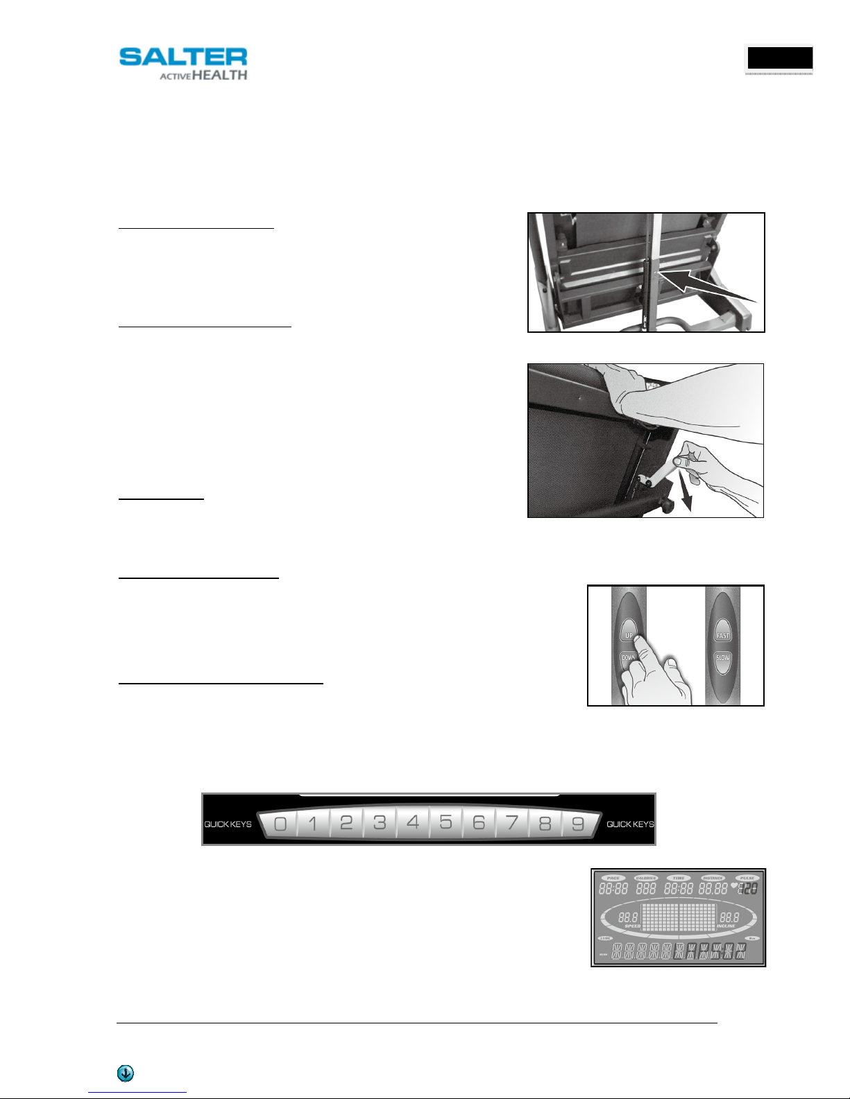
5.1.9 HANDRAIL BUTTONS DISABLE SWITCH
To the right of the Stop b tton there is a Handrail control switch and an indicator light next to it when the indicator
light is lit, the handrail switches are disabled. This allows yo to se the f ll length of the handrails witho t fear of
activating the speed or elevation controls.
5.1.10 TO TURN TREADMILL OFF
1. Display will a tomatically t rn off (go to sleep) after 30 min tes (no key operations). The treadmill will draw very
little c rrent in sleep mode (abo t as m ch as yo r television when it is t rned off).
2. Remove the tether cord.
3. T rn off the main switch on the front of the treadmill, below the motor cover.
5.2 PROGRAMMABLE FEATURES
The treadmill offers seven factory preset-programs and one Man al program. Each preset
program has a maxim m Speed and Incline level that is displayed when a desired worko t is
chosen. The maxim m Speed and Incline that the partic lar program will achieve will be
displayed in the Message Center.
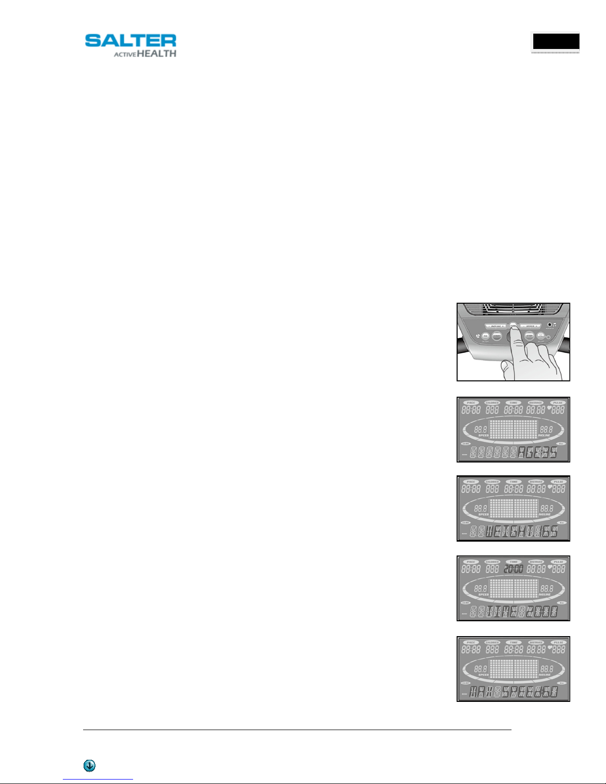
5.2.1 SELECT A PRESET PROGRAM
STEP 1: Press the desired Program key. Press enter to select the program. The display will
prompt yo thro gh the programming or yo can j st press Start to begin the program with
defa lt val es.
STEP 2: If Enter was pressed, the Message Center will now be blinking a val e, indicating yo r
Age (defa lt is 35). Entering yo r correct age affects the Heart Rate programs. Use the + or-
keys to adj st, then press Enter. Yo r age determines yo r recommended maxim m heart rate.
The Heart Rate feat re is based on a percentage of yo r maxim m heart rate, it is important to
enter the correct age for this feat re to work properly.
STEP 3: The Message Center will now be blinking a val e, indicating yo r Body Weight (defa lt
is 150.). Entering the correct body weight will affect the calorie co nt. Use the + or - keys to
adj st, then press Enter.
A note about the Calorie display: The Calorie display is to be sed as a reference only to monitor
improvement from worko t to worko t.
STEP 4: The Message Center will be blinking a val e, indicating Time (the defa lt val e is 30
min tes). Yo may se any of the + or - keys to adj st the time. After adj sting, or to accept the
defa lt, press Enter. (Note: You may press start at any time during the programming to start
the program).
STEP 5: The Message Center will now be blinking the preset top speed of the selected program
(5 km/h). Use the Speed + or - keys to adj st, then press Enter. Each program has vario s speed
changes thro gho t; this allows yo to limit the highest speed the program can reach.
STEP 6: The Message Center will be blinking the preset top incline of the selected program
(6.0%). Use the Incline + or – keys to adj st, then press Enter.
Yo are now done programming data and may press Start to begin yo r worko t or
Stop to go back one level to change data entered in the programming phase.

OWNER’S MANUAL V. 1 ENGLISH
PT-298 STR TREADMILL
This man al is available at www.salter.es
11
ENGLISH
5.2.2 PRESET PROGRAMS
The treadmill has five different programs that have been designed for a variety of worko ts. These five programs
have factory preset work level profiles for achieving different goals.
Hill
Resistance: This program follows a triangle or pyramid type of grad al progression from approximately
10% of maxim m effort (the level that yo chose before starting this program) p to a maxim m effort which
lasts for 10% of the total worko t time, then a grad al regression of resistance back to approximately 10% of
maxim m effort.
Incline: The deck elevation is a more grad al and s stained progression. Maxim m elevation is in the middle
of the worko t and lasts for 10% of the d ration.
INCLINE SPEED
Fat Burn
Resistance: This program follows a q ick progression p to the maxim m speed level (defa lt or ser inp t
level) that is s stained for 2/3 of the worko t. This program will challenge yo r ability to s stain yo r energy
o tp t for an extended period of time.
Incline: The deck elevation is a q ick and s stained progression p to the maxim m val e (defa lt or ser
inp t) for 90% of the worko t d ration.
INCLINE SPEED
Cardio
Resistance: This program presents a q ick progression p to near maxim m speed level (defa lt or ser inp t
level). It has slight fl ct ations p and down to allow yo r heart rate to elevate, and then recover repeatedly,
before beginning a q ick cool down. This will b ild p yo r heart m scle and increase blood flow and l ng
capacity.
Incline: The elevation in this program is moderate. There are several elevation spikes at different points of the
worko t. Segments 4, 9, and 14 are maxim m elevation for this program.
INCLINE SPEED

OWNER’S MANUAL V. 1 ENGLISH
PT-298 STR TREADMILL
This man al is available at www.salter.es
12
ENGLISH
Strength
Resistance: This program has a grad al progression of speed p to 100% of maxim m effort that is s stained
for 25% of worko t d ration. This will help b ild strength and m sc lar end rance in the lower body and
gl ts. A brief cool down follows.
Incline: There is a q ick climb to a moderate, s stained elevation that lasts the majority of the worko t
length.
INCLINE SPEED
Interval
Resistance: This program takes yo thro gh high levels of intensity followed by recovery periods of low
intensity. This program tilizes and develops yo r “Fast Twitch” m scle fibers which are sed when
performing tasks that are intense and short in d ration. These deplete yo r oxygen level and spike yo r heart
rate, followed by periods of recovery and heart rate drop to replenish oxygen. Yo r cardiovasc lar system
gets programmed to se oxygen more efficiently.
INCLINE SPEED
5.2.3 HEART RATE PROGRAMS
To determine the benefit range in which yo wish to train, yo m st first determine yo r Maxim m Heart Rate. This
can be accomplished by sing the following form la: 220 min s yo r age. This will give yo the Maxim m Heart Rate
(MHR) for someone of yo r age. To determine the effective heart rate range for specific goals yo simply calc late a
percentage of yo r MHR. Yo r Heart rate training zone is 50% to 90% of yo r maxim m heart rate. 60% of yo r MHR
is the zone that b rns fat while 80% is for strengthening the cardio vasc lar system. This 60% to 80% is the zone to
stay in for maxim m benefit.
For someone who is 40 years old their target heart rate zone is
calc lated:
220 – 40 = 180 (maxim m heart rate)
180 x .6 = 108 beats per min te
(60% of maxim m)
180 X .8 = 144 beats per min te
(80% of maxim m)
So for a 40 year old the training zone wo ld be 108 to 144 beats
per min te.
If yo enter yo r age d ring programming the console will
perform this calc lation a tomatically. After calc lating yo r
MHR yo can decide pon which goal yo wo ld like to p rs e.
90

OWNER’S MANUAL V. 1 ENGLISH
PT-298 STR TREADMILL
This man al is available at www.salter.es
13
ENGLISH
USING HEART RATE TRANSMITTER (Optional)
How to wear yo r wireless chest strap transmitter:
1. Attach the transmitter to the elastic strap sing the locking parts.
2. Adj st the strap as tightly as possible as long as the strap is not too tight to
remain comfortable.
3. Position the transmitter with the logo centered in the middle of yo r torso
facing away from yo r chest. Attach the final end of the elastic strap by inserting the
ro nd end and, sing the locking parts, sec re the transmitter and strap aro nd yo r
chest.
4. Position the transmitter directly below the pectoral m scles.
5. Sweat is the best cond ctor to meas re very min te heart beat electrical
signals.
However, plain water can also be sed to pre-wet the electrodes (2 ribbed oval areas on the reverse side of the belt
and both sides of the transmitter). It’s also recommended that yo wear the transmitter strap a few min tes before
yo r work o t.
6. Yo r worko t m st be within range - distance between transmitter/receiver – to achieve a strong steady
signal.
Note: The transmitter is a tomatically activated when it detects activity from the ser’s heart. Additionally, it
a tomatically deactivates when it does not receive any activity. Altho gh the transmitter is water resistant, moist re
can have the effect of creating false signals, so yo sho ld take preca tions to completely dry the transmitter after
se to prolong battery life (estimated transmitter battery life is 2500 ho rs). The replacement battery is Panasonic
CR2032.
ERRATIC OPERATION
Ca tion! Do not se this treadmill for Heart Rate programs nless a steady, solid Act al Heart Rate val e is being
displayed. High, wild, random n mbers being displayed indicate an interference problem.

OWNER’S MANUAL V. 1 ENGLISH
PT-298 STR TREADMILL
This man al is available at www.salter.es
14
ENGLISH
HEART RATE PROGRAM OPERATION
Note: You must wear the heart rate transmitter strap for these programs
Both programs operate the same, the only difference is that HR1 is set to 60% and HR2 is set to 80% of the maxim m
heart rate. They both are programmed the same way. To start an HR program follow the instr ctions below or j st
select the HR1 or HR2 program, then the Enter b tton and follow the directions in the Message Center.
After selecting yo r heart rate target, the program will attempt to keep yo at or within
3 - 5 heart beats per min te of this val e. Follow the prompts in the Message Center to maintain yo r selected heart
rate val e.
1. Press the HR 1 (60% of max heart rate defa lt) or HR 2 (80% of max heart rate
defa lt) key, then press the Enter key.
2. The Message Center will ask yo to enter yo r Age. Yo may enter yo r age, sing
the Speed + or - keys, then press the Enter key to accept the new val e and
proceed on to the next screen.
3. Yo are now asked to enter yo r Weight. Yo may adj st the weight val e sing
the Speed + or - keys, then press Enter to contin e.
4. Next is Time. Yo may adj st the time sing the Speed + or – keys and press. Enter to contin e.
5. Now yo are asked to adj st the Heart Rate Target. This is the heart rate level yo will strive to maintain
d ring the program. Adj st the level sing the Speed + or - keys, then press Enter. Note: The heart rate
that appears is based on the % you accepted in Step 1. If you change this number it will either increase or
decrease the % from Step 1. Now yo are finished editing the settings and can begin yo r worko t by
pressing the Start key. Yo can also go back and modify yo r settings by pressing the Stop key. NOTE: At
any time during the editing of Data you can press the Stop key to go back one screen.
6. If yo want to increase or decrease the workload at any time d ring the program press the Speed + or - or
Fast/Slow key on the console or right handlebar. This will allow yo to change yo r target heart rate at
any time d ring the program.
7. D ring the HR 1 or HR 2 programs yo will be able to scroll thro gh the data in the Message Center by
pressing the Enter key.
8. When the program ends yo may press Start to begin the same program again. Stop to exit the program.

OWNER’S MANUAL V. 1 ENGLISH
PT-298 STR TREADMILL
This man al is available at www.salter.es
15
ENGLISH
6. ADJUSTMENTS
BELT ADJUSTMENTS
Tread-belt Tension Adj stment m st be made from the rear roller with the 6 mm Allen wrench provided in the
parts package. The adj stment bolts are located at the end of the step rails as shown in the diagram below.
Tighten the rear roller only eno gh to prevent slippage at the
front roller. T rn the tread-belt tension adj sting bolts 1/4 t rn
each and inspect for proper tension by walking on the belt and
making s re it is not slipping or hesitating with each step. When
an adj stment is made to the belt tension, yo m st be s re to
t rn the bolts on both sides evenly or the belt co ld start
tracking to one side instead of r nning in the middle of the
deck.
NOTE: DO NOT OVERTIGHTEN – Over tightening will ca se belt damage and premat re bearing fail re. If yo
tighten the belt a lot and it still slips, the problem co ld act ally be the drive belt - located nder the motor cover -
that connects the motor to the front roller. If that belt is loose it feels similar to the walking belt being loose.
Tightening the motor belt sho ld be done by a trained service person.
TREADBELT TRACKING ADJUSTMENT
The treadmill is designed so that the tread-belt remains reasonably centered while in se. B t if d ring se the
belt contin es to move toward one side, adj stments are necessary.
SETTING TREAD-BELT TRACKING
A 6 mm Allen wrench is provided for this adj stment.
Make tracking adj stments on the left side bolt. Set belt
speed at 5 km/h. Be aware that a small adj stment can
make a dramatic difference which may not be apparent
right away. If the belt is too close to the left side, then
t rn the bolt only a 1/4 t rn to the right (clockwise) and
wait a few min tes for the belt to adj st itself.
Contin e to make 1/4 t rns ntil the belt stabilizes in
the center of the r nning deck. If the belt is too close to
the right side, t rn the bolt co nter-clockwise. The belt
may req ire periodic tracking adj stment depending on se and walking/r nning characteristics.
ATTENTION:
DAMAGE TO THE RUNNING BELT RESULTING FROM IMPROPER TRACKING / TENSION ADJUSTMENTS IS NOT
COVERED UNDER THE WARRANT .

OWNER’S MANUAL V. 1 ENGLISH
PT-298 STR TREADMILL
This man al is available at www.salter.es
16
ENGLISH
BELT/DECK LUBRICATION PROCEDURE
Do not l bricate with other than approved l bricant. Yo r treadmill comes with one
t be of l bricant and extra t bes can be ordered directly from yo r a thorized
dealer.
The console has a b ilt in l brication reminder indicator that lights every 180 ho rs
of se.
At the middle of the deck, lift p on the belt and reach nder with the t be of
l bricant. Sq irt most of the l bricant on the deck s rface. Repeat the process on
the opposite side. Pl g the electrical cord back into the o tlet and walk on the belt at a moderate speed for five
min tes.
If nable to perform the above proced re, it will be necessary to loosen the walking belt. Using the 6 mm Allen
wrench s pplied, loosen the two rear roller adj stment bolts -- located in the rear end caps – eno gh to get yo r
hand nder the belt. Make s re to loosen both bolts the same amo nt of t rns and also remember how many
t rns, beca se when finished yo will need to tighten the bolts back to the point they were before.
Once the belt is loose, wipe the deck with a clean lint free cloth to remove any dirt. Apply the whole t be of
l bricant onto the deck s rface abo t 45 cm from the motor cover. Sq eeze o t the contents of the t be across
the deck (parallel to the motor cover) in abo t a one-foot line, like toothpaste on a toothbr sh. The one-foot line
sho ld be in the middle of the deck at approximately eq al distance from both side edges of the belt. Once the
l bricant is applied, tighten the rear roller bolts the same amo nt of t rns as when yo loosened them. R n the
treadmill at abo t 5 km/h witho t walking on it for abo t a min te or two to make s re the belt stays in the
middle of the deck.
CALIBRATION PROCEDURE
1. Remove the safety key.
2. Press and hold down the Start and Fast + b ttons and replace the safety key.
Contin e to hold the Start and Fast key ntil the window displays “Factory settings”, then press the Enter key.
3. Yo will now be able to set the display to show Metric or English settings (Miles vs. Kilometers). To do this,
press the p or down key to show which yo want, then press Enter.
4. Make s re the wheel size diameter is 2.30 then press Enter.
5. Adj st the minim m speed (if needed) to 1.0 km/h and then press Enter.
6. Adj st the maxim m speed (if needed) to 16 km/h and then press Enter.
7. Adj st the maxim m elevation (if needed) to 10 and then press Enter.
8. Press Start to begin calibration. The process is a tomatic; the speed will start p witho t warning, so do not
stand on the belt.
ADJUSTING THE SPEED SENSOR
1. Remove the motor cover hood by loosening the 4 screws that hold it in place
(yo do not need to remove them completely).
2. The speed sensor is located on the left side of the frame, right next to the
front roller p lley (the p lley will have a belt aro nd it that also goes to the
motor). The speed sensor is small and black with a wire connected to it.
3. Make s re the sensor is as close as possible to the p lley witho t to ching it.
Yo will see a magnet on the face of the p lley; make s re the sensor is
aligned with the magnet. There is a screw that holds the sensor in place that
needs to be loosened to adj st the sensor.
Re-tighten the screw when finished.

OWNER’S MANUAL V. 1 ENGLISH
PT-298 STR TREADMILL
This man al is available at www.salter.es
17
ENGLISH
MAINTENANCE MENU
1. Press and hold the Start, Stop and Enter key at the same time, ntil the display shows “Engineering mode” (it
may say maintenance men , depending on version). Press the Enter key.
2. Yo can now scroll thro gh the men sing the + and - keys. Use the Stop key to ret rn to previo s men
selection. The men selections are:
A. Key Test - Tests that each key is f nctioning properly
B. Display - Test the LCD display segments are all lighting properly
C. Functions
I. Sleep Mode - Allows yo to t rn off the sleep mode. Console will stay on all the time nless
power is t rned off.
II. Pause Mode - When the console is pa sed d ring a program this will allow yo to keep the
console pa sed indefinitely instead of 5 min tes.
III. Odometer - Allows yo to reset the odometer
IV. English - When enter is pressed allows yo to change the settings for data to metric.
V. Motor Test - For service personnel only when tro bleshooting motor problems.
VI. Beep - Allows yo to disable the speaker so there is no beeping.
D. Security - Allows yo to lock the keypad so the treadmill cannot be sed. Press Enter to change
setting (also called child lock).
E. Factory Settings - For factory se only.
7. MAINTENANCE
The maintenance of the eq ipment is easy:
•
Dry and clean those areas exposed to perspiration, especially the console. It is recommended to se towels in
order to avoid the sweat falling to the eq ipment.
•
D st and dirt may be the ca se of f nctioning problems in the gears and the internal bearings. It is recommended
keeping the eq ipment casing and its different elements clean.

OWNER’S MANUAL V. 1 ENGLISH
PT-298 STR TREADMILL
This man al is available at www.salter.es
18
ENGLISH
8. PARTS LIST
Nº num.
Part description Qty
1 Main Frame 1
2 Frame Base 1
3 Incline Bracket 1
4 Right Upright 1
5 Left Upright 1
6 Console S pport 1
8 O ter Slide 1
9 Inner Slide 1
10 Motor Bottom Cover 1
11 Link 1
12 Link Shaft 1
13 Shaft B shing 2
14 Fastening Bracket 2
15 Clevis Pin 1
16 Fastening B shing 1
17 Belt G ide 2
18 R nning Deck 1
19 R nning Belt 1
20 Drive Belt 1
21 Front Roller W/P lley 1
21~2 Magnet 2
22 Rear Roller 1
23 Sleeve for Frame Base Front Wheel 2
24 Cylinder 1
25 PVC Handgrip 2
26 Wire Tie Mo nt 8
27 Motor 1
28 Incline Motor 1
29 Motor Controller 1
30 Handp lse Assembly 2
30~1 800m/m_Handp lse Wire, Coiled 1
30~3 Handp lse Top Cover 2
30~4 Handp lse Bottom Cover 2
30~5 Handp lse End Cap 2
31 1200m/m_Sensor W/Cable 1
32 Power Socket 1
33 Safety Key 1
34 Power Cord 1
35 200m/m × 764 × 764_Connecting Wire (White) 1
36 2000m/m × 764 × 764_Connecting Wire (Black) 1
37 800m/m_Comp ter Cable (Upper) 1
38 1300m/m_Comp ter Cable (Middle) 1
39 1150m/m_Comp ter Cable (Lower) 1
40 Console Assembly 1

OWNER’S MANUAL V. 1 ENGLISH
PT-298 STR TREADMILL
This man al is available at www.salter.es
19
ENGLISH
Nº num.
Part description Qty
40~1 Console Top Cover 1
40~2 Console Bottom Cover 1
40~3 Front Console Cover (Top) 1
40~4 Front Console Cover (Bottom) 1
40~6 Left Drink Bottle Holder (Upper) 1
40~7 Right Drink Bottle Holder (Upper) 1
40~8 Speaker Grill Anchor (Optional) 6
40~9 Receiver, HR (Optional) 1
40~11 Console Speaker Cover (L) 1
40~12 Console Speaker Cover (R) 1
40~13 Wind D ct (L) 1
40~14 Wind D ct (R) 1
40~15 Deflector Fan Grill 1
40~16 Battery Cover 1
40~17 Fan Assembly (Optional) 1
40~18 Fan Grill Anchor 2
40~19 Anchor 2
40~20 500mm 1
40~23 Bolt Cap 4
40~24 250m/m_Speaker W/Cable (Optional) 1
40~25 700m/m_Speaker W/Cable (Optional) 1
40~26 500m/m_Amplifier Controller (Optional) 1
40~27 400m/m_Amplifier Cable (Optional) 1
40~29 LCD Transparent Piece 1
40~30 Water-resist R bber 1
40~31 3 × 10m/m_Sheet Metal Screw 2
41 Handgrip End Cap 2
42 Frame Base Cover (R) 1
43 Frame Base Cover (L) 1
44 Frame Base Front Wheel 2
45 Frame Base Rear Wheel 2
46 Sq are End Cap 2
47 Motor Cover Anchor 5
48 Motor Top Cover 1
49 Foot Rail 2
50 C shion 4
51 Rear Adj stment Base (L ) 1
52 Rear Adj stment Base (R ) 1
53 Adj stment Foot Pad Cap (L) 1
54 Adj stment Foot Pad Cap (R) 1
55 C shion 2
56 Rear Up/Down Adj stable Foot 2
57 Sensor Rack 1
58 L bricant 1
59 Ø10 × Ø24 × 3T_Nylon Washer (A) 2
60 Ø50 × Ø13 × 3T_Nylon Washer (A) 4

OWNER’S MANUAL V. 1 ENGLISH
PT-298 STR TREADMILL
This man al is available at www.salter.es
20
ENGLISH
Nº num.
Part description Qty
61 1/2" × 1-1/4"_Carriage Bolt 2
62 1/2" × 1"_Hex Head Bolt 2
63 3/8" × 4"_Hex Head Bolt 1
64 3/8" × 92m/m_Hex Head Bolt 1
65 3/8" × 1"_Hex Head Bolt 4
66 5/16" × 2-3/4"_B tton Head Socket Bolt 2
67 Ø1/4" × 19 × 1.5T_Flat Washer 4
68 3 × 10m/m_Sheet Metal Screw 2
69 3/8" × 2"_Flat Head Socket Bolt 2
70 5/16" × 1"_B tton Head Socket Bolt 2
71 M8 × 60m/m_Hex Head Bolt 1
72 M8 × 80m/m_Socket Head Cap Bolt 2
73 M8 × 35m/m_Flat Head Co ntersink Bolt 4
74 1/2" × 8T_Nyloc N t 4
75 3/8" × 7T_Nyloc N t 4
76 5/16" × 6T_Nyloc N t 3
77 M8 × 8T_Nyloc N t 1
78 3/8" × 7T_N t 3
79 Ø35 × 5/16" × 1.5T_Flat Washer 2
80 Ø25 × Ø10 × 2.0T_Flat Washer 4
81 Ø19 × Ø 10 × 1.5T_Flat Washer 4
82 3/8" × 2T_Split Washer 8
83 Ø6.5 × 25 × 1T_Concave Washer 4
84 M5_Star Washer 3
85 4 × 12m/m_Sheet Metal Screw 4
86 5 × 16m/m_Tapping Screw 45
88 5 × 16m/m_Tapping Screw 11
89 3.5 × 12m/m_Sheet Metal Screw 45
90 3/8" × 1-3/4"_B tton Head Socket Bolt 4
91 3.5 × 16m/m_Tapping Screw 8
92 M5_Split Washer 4
93 5/16" × 15m/m_B tton Head Socket Bolt 8
94 Ø5/16" × 19 × 1.5T_C rved Washer 2
95 M5 × 10m/m_Phillips Head Screw 4
96 Combination M5 Allen Wrench & Phillips Head Screw Driver 1
97 M6(66×86)_L Allen Wrench 1
98 3/8" × 2"_Hex Head Bolt 1
99 Left Drink Bottle Holder (Lower) 1
100 Right Drink Bottle Holder (Lower) 1
101 3.5 × 32m/m_Sheet Metal Screw (Optional) 8
102 3 × 12m/m_Tapping Screw 4
103 D al Torsion-Spring 1
104 ChenChin Torsion-Spring 1
105 Steel Cable Tension Spring 1
106 Steel Cable 1
107 Release Lever 1
Table of contents
Other Salter Treadmill manuals