manuals.online logo
Brands
  1. Home
  2. •
  3. Brands
  4. •
  5. Salvajor
  6. •
  7. Commercial Food Equipment
  8. •
  9. Salvajor G Series User manual

Salvajor G Series User manual

STARTING SERIAL NUMBER
MODEL VOLTAGE PHASE SERIAL NO.
75 115/230 1 72139
75 208 1 71135
75 208-230/460 3 73142
100 115/230 1 9318
100 208 1 3709
100 208-230/460 3 8401
150 115/230 1 152115
150 208 1 151144
150 208-230/460 3 153322
200 115/230 1 6169
200 208 1 3698
200 208-230/460 3 16441
300 208-230/460 3 11850
500 208-230/460 3 8472
750 208-230/460 3 5100
These instructions are designed to assist in the rebuilding of Salvajor Disposers.
Not all parts in this kit will be identical matches to the parts removed.
The changes made are part of our ongoing commitment to quality,
increased longevity and durability of Salvajor Disposers.
All repairs should be made according to local codes and by a qualified technician.
SEAL KIT REPLACEMENT
Series G, H & J
Part Number KSH123
(For Disposer Models 75-750)
Manufacturers of Commercial Food Waste Solutions - Since 1944
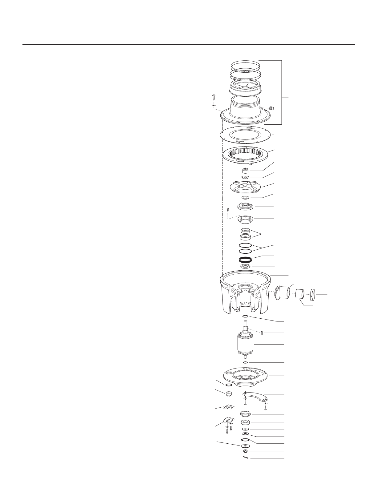
Disposer Disassembly
TOP HOUSING ASSEMBLY
#996045 CENTER GASKET
SHREDDER
#7814RN ROTOR NUT
#997092 LOCKWASHER
FACE PLATE
#996025 ROTOR SHAFT GASKET
#12151 0-RINGS
#123/222
O-RING
KLIXON
(Thermal
Overload)
KLIXON
COVER
GASKET
KLIXON
COVER
#987001
RETAINING
WASHER
#980132 ROTOR BASE
#993001 TOP END BELL
INSERT W/SEAL
#985001 TOP BEARING CUP/CONE
#ANL79X15S TOLERANCE RING
#S67350 BOTTOM VARILIP SEAL
MOTOR HOUSING
RUBBER DRAIN OUTLET
CLAMP
DRAIN INSERT
#11026 O-RING
#997070 KEY
MOTOR ROTOR
#996020 O-RING
BOTTOM END BELL
JUNCTION BOX COVER
#996023 RUBBER ISOLATOR
#6205 BOTTOM BEARING
#987002 DRIVE WASHER
#996024 FRICTION WASHER
#987003 WAVY WASHER
#997050 CASTLE NUT
#997051 COTTER PIN
Step 1
SHUT OFF POWER TO THE DISPOSER CONTROL
and remove disposer from service. Remove the top housing
by removing the eight top housing bolts. Remove the center
gasket located on the top of the cutters.
Note: For easier removal, the top housing can be
left attached to the sink, remove the eight bolts
so that only the disposer bottom comes off. This
eliminates the need to undo the plumbing to the
top housing.
Step 2 Turn the unit upside down so the junction box and
thermal overload covers are facing up and remove both of
these covers. Remove the black rubber gasket over the
thermal overload and pull the thermal overload out of its
seat by pulling on the red button. Remove the o-ring and
push the thermal overload back through the hole so that it is
inside the bottom of the unit.
Step 3 Turn the unit back over and now you are looking
at the cutters. The stationary cutter is the shredder and the
cutter in the middle that spins is the face plate. The piece
under the face plate is the rotor base. Remove the shredder
by inserting a screwdriver in between the face plate and the
shredder and pry it out. Remove the 1-1/4” rotor nut (1-10
hp)or the 3/8” rotor bolt (older style 1 hp). Lift face plate off
the motor shaft, remove the rotor shaft gasket and the rotor
base the same way as the face plate. Next remove the four
screws in the top end bell insert.
Note: Rotor base might come off attached to the
face plate, if so, separate these parts as the rotor
shaft gasket is located between these parts.
Step 4 Lay unit on its side, use a RUBBER mallet to strike
the large threaded end (7/8-14)of the motor shaft, driving it
out the bottom. The motor rotor will come out with the bot-
tom end bell assembly still attached.
Note: Verify that Step 2 is complete before com-
pleting Step 4 or the thermal overload wiring may
be damaged.
Step 5 Turn the motor housing upside down and remove the
top end bell insert by pushing it out from inside the motor bar-
rel. After the insert is out, the tolerance ring and o-rings will also
need to be removed if they did not come out with the insert.
Step 6 Using a long screwdriver, drive out the bottom seal
from the motor barrel side of the unit. It will come out similar
to the top end bell insert.
Step 7 Remove the cotter pin and 1/2” castle nut from the
bottom end bell assembly and remove the four washers. Use
a RUBBER mallet to separate the bottom end bell assem-
bly and the motor rotor. Once separated, remove the bottom
sealed bearing and the orange bottom end bell rubber isolator.
You are now ready to install the seal kit. Items in bold are included in kit.
Step 1 With disposer housing upright, press the bottom varilip seal (S67350), open side up, into the bottom of the
bearing pocket. The upper lip of the bottom varilip seal should be flush with the bottom of the bearing pocket.
Step 2 Place the tolerance ring (ANL79X15S)into the
bearing pocket and push out against the outer wall.
Step 3 Place one o-ring (12151)into bottom of the bearing
pocket and place the second o-ring around the bottom por-
tion of the top end bell assembly.
Step 4 Push cardboard man-
drel to the top of seal in the top
end bell assembly. Do not remove.
Assemble top bearing cup/cone
as shown. Press the pre-greased
top bearing cup\cone assembly
(985001)into the top end bell as-
sembly (993001) as shown.
Note: The top bearing
cup/cone should go into the top end bell assembly
so the cone taper (narrow side) faces down.
Step 5 Carefully place top end bell assembly, complete
with top bearing cup/cone, into bearing pocket. Make sure
the tolerance ring remains against the outer wall of the bearing pocket. Tighten the four screws.
Step 6 If stator and motor housing insert were removed, turn disposer housing upside down and line up motor lead
outlet on the motor housing insert with the slot in the disposer housing. Insert the new stator and motor housing insert.
Using a rubber mallet, seat the motor housing insert by tapping on the insert.
Step 7 Place the new o-ring (11026) on the larger end of the the motor rotor shaft and new o-ring (996020)on the
smaller end in the slots provided and insert the motor rotor shaft larger threaded end into the disposer housing mak-
ing sure it bottoms out in the top bearing cup/cone. Once the motor rotor shaft is in place, turn the disposer upright
onto a prop, such as a block of wood, under the bottom of the motor rotor shaft to assure it stays in the top bearing.
Step 8 Remove the cardboard mandrel from the top end bell assembly. Immediately place the rotor base (980132)
on the motor rotor shaft and align the key slots. Once the rotor base is in place, tap the key (997070)into the slot
until it bottoms out.
Note: New style rotor base may be smaller than the rotor base that was taken out.
Step 9 Insert the rotor shaft gasket (996025 / RSG)in the center of the rotor base around the motor rotor shaft.
Step 10 Place the face plate on top of the rotor base and align tabs on bottom for proper seating. Install the lock
washer (997092- or 38L)and 1-1/4” rotor nut (7814RN-)or 3/8” rotor bolt with o-ring (38162/11012)on the shaft and
tighten until the rotor nut, or bolt depending on series of disposer, bottoms out completely and the face plate is tight
against the rotor base.
Installation instructions continued on back page ➔
Seal Kit Installation
CARDBOARD
MANDREL
(Remove in step #8)
TOP END BELL
ASSEMBLY
(Seal included)
SCREWS
TOP BEARING
CUP/CONE
CARDBOARD
MANDREL
TOP END
BELL ASSEMBLY
TOP BEARING
CUP/CONE
Step 11 Insert the bottom end bell into the bottom of the disposer housing and pull the thermal overload though the hole
provided in the bottom end bell. Place o-ring (123- 3/4 to 3 h.p. or 222- 5-10 h.p.)around the thermal overload and push
back into bottom end bell hole. Install thermal overload cover and gasket securing them with two 10-32 hex head bolts
and washers. Place the bottom end bell on the disposer housing lining up the junction box opening in the bottom end bell
with the junction box in the disposer housing. Carefully pull all the stator wires into the junction box and make sure you
have not pinched any wires. Tap the bottom end bell into place with a rubber mallet.
Step 12 Place bottom end bell rubber insulator
(996023)in to the bottom bearing pocket of the bottom
end bell.
Step 13 Place bottom bearing (6205)over the
motor rotor shaft into the bottom bearing pocket
making sure not to crimp the bottom end bell
rubber insulator.
Note: Bearing must seat completely in
bottom end bell.
Step 14 Place the drive washer (997002)over
threads on the motor rotor shaft and against the
bottom bearing.
Step 15 Place the friction washer (996024)over
the threaded end of the motor shaft and on top of the
drive washer.
Step 16 Place the wavy washer (987003)over the
shaft and locate it on the drive washer around the
outside of the friction washer.
Step 17 Place the retaining washer (987001)over the shaft and up against the wavy washer and the friction washer.
Step 18 Screw the 1/2” castle nut (997050)on the motor rotor shaft. This should be tightened down and then backed
off and then tighten to 48 inch lbs with a torque wrench. NOTE: Over or under torquing can damage the bearing!
Step 19 Push cotter pin (997051)through hole in motor shaft. Bend around castle nut to secure.
Note: There should be no vertical play in the motor rotor shaft at this time.
Step 20 Turn the disposer upright and check for up and down play and that unit spins freely. Insert the shredder by
lining up the four tabs with four of the motor housing bolts and tap into place.
Step 21 Place the center gasket (996045)and remove center of gasket so that the inside diameter matches
shredder. Place top housing on motor housing and secure with the eight motor housing bolts.
Seal Kit Installation
CARDBOARD
MANDREL
(Remove in step #8)
TOP END BELL
ASSEMBLY
(Seal included)
SCREWS
TOP BEARING
CUP/CONE
4530 East 75th Terrace Kansas City, MO 64132-2081, USA
Toll Free: 1.888.725.8256
I
Fax: 1.800.832.9373
[email protected]
I
www.salvajor.com
Printed in USA
Form No.SKR (04-18)

This manual suits for next models

3

Other Salvajor Commercial Food Equipment manuals

Salvajor ScrapMaster 300-SM Manual

Salvajor

Salvajor ScrapMaster 300-SM Manual

Salvajor TroughVeyor TVL Series Manual

Salvajor

Salvajor TroughVeyor TVL Series Manual

Popular Commercial Food Equipment manuals by other brands

CRIOCABIN ESPRIT instruction manual

CRIOCABIN

CRIOCABIN ESPRIT instruction manual

EPTA COSTAN BATIK manual

EPTA

EPTA COSTAN BATIK manual

Hatco AMERICAN RANGE MSD-1 owner's manual

Hatco

Hatco AMERICAN RANGE MSD-1 owner's manual

Jackson MSC 200 Series Service manual

Jackson MSC

Jackson MSC 200 Series Service manual

Arneg Lisbona Direction for Installation and Use

Arneg

Arneg Lisbona Direction for Installation and Use

LEM 534 Use & maintenance

LEM

LEM 534 Use & maintenance

saro EGN 650 BT operating instructions

saro

saro EGN 650 BT operating instructions

Nemco 6152-24 Operating and maintenance instructions

Nemco

Nemco 6152-24 Operating and maintenance instructions

Costan ARCADE ECO User instructions

Costan

Costan ARCADE ECO User instructions

Henny Penny McDonald's LOV MVE 07X Electric Series quick start guide

Henny Penny

Henny Penny McDonald's LOV MVE 07X Electric Series quick start guide

Antunes Chick-fil-A ES-600R owner's manual

Antunes

Antunes Chick-fil-A ES-600R owner's manual

Scharfen TC 11 operating instructions

Scharfen

Scharfen TC 11 operating instructions

Fimar MCD/260E Use and maintenance

Fimar

Fimar MCD/260E Use and maintenance

Hendi 273982 User instructions

Hendi

Hendi 273982 User instructions

Rational iCombi Pro Original installation manual

Rational

Rational iCombi Pro Original installation manual

STODDART Culinaire CH.CD Specification, installation and operation manual

STODDART

STODDART Culinaire CH.CD Specification, installation and operation manual

Mono Ecotouch Operation and maintenance manual

Mono

Mono Ecotouch Operation and maintenance manual

Electrolux Professional thermaline MAYA DOBO Series Installation and operating manual

Electrolux Professional

Electrolux Professional thermaline MAYA DOBO Series Installation and operating manual

manuals.online logo
manuals.online logoBrands
  • About & Mission
  • Contact us
  • Privacy Policy
  • Terms and Conditions

Copyright 2025 Manuals.Online. All Rights Reserved.