Sam4s ELLIX 20 User manual

OPERATOR’S Manual
All specifications are subject to change without notice
ELLIX 20
RECEIPT PRINTERٻ
www.AnchorData.co.uk
Anchor Data Systems (NI) Ltd
Unit 36 North City Business Centre
Duncairn Gardens, Belfast, BT15 2GG
(028) 9074 0315 www.AnchorData.co.uk

ٻڈٻ2ٻڈ
Warning - U.S.
This equipment has been tested and found to comply with the limits for a Class A digital
device pursuant to Part 15 of the FCC Rules. These limits are designed to provide
reasonable protection against harmful interference when the equipment is operated in a
commercial environment. This equipment generates uses, and can radiate radio frequency
energy and , if not installed and used in accordance with the instruction manual, may
cause harmful interference to radio communications. Operation of this equipment in a
residential area is likely to cause harmful interference in which case the user will be
required to correct the interference at his own expense.
Notice - Canada
This Apparatus complies with class “A” limits for radio interference as specified in the
Canadian department of communications radio interference regulations.
Get appareil est conforme aux normes class “A” d’interference radio tel que specifier par
ministre canadien des communications dans les reglements d’interference radio.
Caution
Some semiconductor devices are easily damaged by static electricity. You should turn the
printer “OFF”, before you connect or remove the cables on the rear side, in order to guard
the printer against the static electricity. If the printer is damaged by the static electricity,
you should turn the printer “OFF”.
INTRODUCTION
The ELLIX 20 Roll Printer is designed for use with electronic instruments such as system
ECR, POS, banking equipment, computer peripheral equipment, etc.
The main features of the printer are as follows:
1. High speed printing : 52 lines per second.
2. Low noise thermal printing.
3. RS-232 serial / IEEE1284 parallel / USB / Ethernet / Bluetooth / Wireless LAN
interface.
4. The data buffer allows the unit to receive print data even during printing.
5. Peripheral units drive circuit enables control of external devices such as cash drawer.
6. Characters can be scaled up to 64 times compared to it’s original size.
7. Bar code printing is possible by using a bar code command.
8. Different print densities can be selected by DIP switches.
9. 2-dimantional bar code(PDF-417) and Two color printing.
Please be sure to read the instruction in this manual carefully before using your ELLIX20.
NOTES : The socket-outlet shall be near the equipment and it shall
be easily accessible.
www.AnchorData.co.uk

ٻڈٻ3ٻڈ
Table of Contents
CHAPTER 1. SETTING UP THE PRINTER
ډډډډډډډډډډډډډډډډډډډډډډډډ ڏ
G
1-1. UNPACKING ډډډډډډډډډډډډډډډډډډډډډډډډډډډډډډډډډډډډډډډډډډډډډډډډ ڏG
1-2. CONNECTING THE CABLES ډډډډډډډډډډډډډډډډډډډډډډډډډډډډډډډډډډډډډډ ڐG
1-3. CONNECTING THE COMPUTER ډډډډډډډډډډډډډډډډډډډډډډډډډډډډډډډډډډډ ڑG
1-4. CONNECTING THE DRAWER ډډډډډډډډډډډډډډډډډډډډډډډډډډډډډډډډډډډډډ ڒG
1-5. CONNECTING THE POWER SUPPLY ډډډډډډډډډډډډډډډډډډډډډډډډډډډډډډډډ ړG
1-6. INSTALLING OR REPLACING THE PAPER ROLL ډډډډډډډډډډډډډډډډډډډډډډډ ڌڋG
1-6-1. Partition Installation ډډډډډډډډډډډډډډډډډډډډډډډډډډډډډډډډډډ ڌڌG
1-6-2. Wall Mount Installation ډډډډډډډډډډډډډډډډډډډډډډډډډډډډډډډ ڌڍG
1-6-3. Paper Roll Installation ډډډډډډډډډډډډډډډډډډډډډډډډډډډډډډډډ ڌڎG
1-7. ADJUSTMENTS AND SETTINGS ډډډډډډډډډډډډډډډډډډډډډډډډډډډډډډډډډډ ڌڏG
1-7-1. Serial Interface Specificationډډډډډډډډډډډډډډډډډډډډډډډډډډډ ڌڐG
1-7-2. Parallel Interface Specification ډډډډډډډډډډډډډډډډډډډډډډډډډ ڌڑG
1-8. USING THE PRINTER ډډډډډډډډډډډډډډډډډډډډډډډډډډډډډډډډډډډډډډډډډ ڌڒG
1-8-1. Control Panel ډډډډډډډډډډډډډډډډډډډډډډډډډډډډډډډډډډډډډډډډ ڌڒG
CHAPTER 2. HEXADECIMAL DUMPING
ډډډډډډډډډډډډډډډډډډډډډډډډ ڌړ
G
CHAPTER 3. THE SELF TEST
ډډډډډډډډډډډډډډډډډډډډډډډډډډډډډډډډډډ ڌڔ
G
CHAPTER 4. CODE TABLE
ډډډډډډډډډډډډډډډډډډډډډډډډډډډډډډډډډډډډډ ڍڋ
G
CHAPTER 5. CONTROL COMMANDS
ډډډډډډډډډډډډډډډډډډډډډډډډډډډ ڎڍ
G
5-1. EPSON MODE COMMANDS ډډډډډډډډډډډډډډډډډډډډډډډډډډډډډډډډډډډډ ڎڍG
5-2. STAR MODE COMMANDS ډډډډډډډډډډډډډډډډډډډډډډډډډډډډډډډډډډډډډډ ڎڐG
APPENDIX
ډډډډډډډډډډډډډډډډډډډډډډډډډډډډډډډډډډډډډډډډډډډډډډډډډډډ ڎړ
G
A. MISCELLANEOUS NOTES ډډډډډډډډډډډډډډډډډډډډډډډډډډډډډډډډډډډډډډډډ ڎړG
B. TWO-COLOR PRINTING ډډډډډډډډډډډډډډډډډډډډډډډډډډډډډډډډډډډډډډډډډ ڏڋG
C. RECOVERY FORM THE AUTO CUTTER ERROR ډډډډډډډډډډډډډډډډډډډډډډډډډ ڏڌG
D.GPRINTER HEAD CLEANING ډډډډډډډډډډډډډډډډډډډډډډډډډډډډډډډډډډډډډډ ڏڍG
E. CONNECTORS ډډډډډډډډډډډډډډډډډډډډډډډډډډډډډډډډډډډډډډډډډډډډډډډډ ڏڎG
D.1 Interface Connector ډډډډډډډډډډډډډډډډډډډډډډډډډډډډډډډډډډډډ ڏڏG
D.2 Drawer Connector ډډډډډډډډډډډډډډډډډډډډډډډډډډډډډډډډډډډډډډ ڏڒG
F. ERROR STATUSډډډډډډډډډډډډډډډډډډډډډډډډډډډډډډډډډډډډډډډډډډډډډډډ ڏړG
G. ADJUSTING THE ROLL PAPER NEAR-END SENSOR LOCATIONډډډډډډډډډډډډډ ڐڋG
H. SPECIFICATION ډډډډډډډډډډډډډډډډډډډډډډډډډډډډډډډډډډډډډډډډډډډډډډ ڐڌG
G.1 General Printer specification ډډډډډډډډډډډډډډډډډډډډډډډډډډډډډ ڐڌG
G.2 Paper specification ډډډډډډډډډډډډډډډډډډډډډډډډډډډډډډډډډډډډډ ڐڍG
www.AnchorData.co.uk

ٻڈٻ4ٻڈ
Chapter 1. Setting Up the Printer
1-1. Unpacking
Your printer box should include these items. If any items are damaged or missing, please
contact your dealer for assistance.
www.AnchorData.co.uk

ٻڈٻ5ٻڈ
1-2. Connecting the Cables
You can connect up to three cables to the printer. They are all connected to the connector
panel on the back of the printer, which is shown as below:
NOTES : Before connecting any of the cables, make sure that both
the printer and the computer should be turned off.
www.AnchorData.co.uk

ٻڈٻ6ٻڈ
1-3. Connecting the computer
You need an appropriate interface cable.
1. Plug the cable connector securely into the printer’s interface connector.
2. Tighten the screws on both sides of the cable connector.
3. Attach the other end of the cable to the computer.
www.AnchorData.co.uk

ٻڈٻ7ٻڈ
1-4. Connecting the Drawer
WARNING:
Use a drawer that matches the printer specification. Using an improper drawer may
damage the drawer as well as the printer.
CAUTION:
Do not connect a telephone line to the drawer kick-out connector; otherwise the printer
and the telephone line may be damaged.
Plug the drawer cable into the drawer kick-out connector on the back of the printer next to
the power supply connector.
www.AnchorData.co.uk

ٻڈٻ8ٻڈ
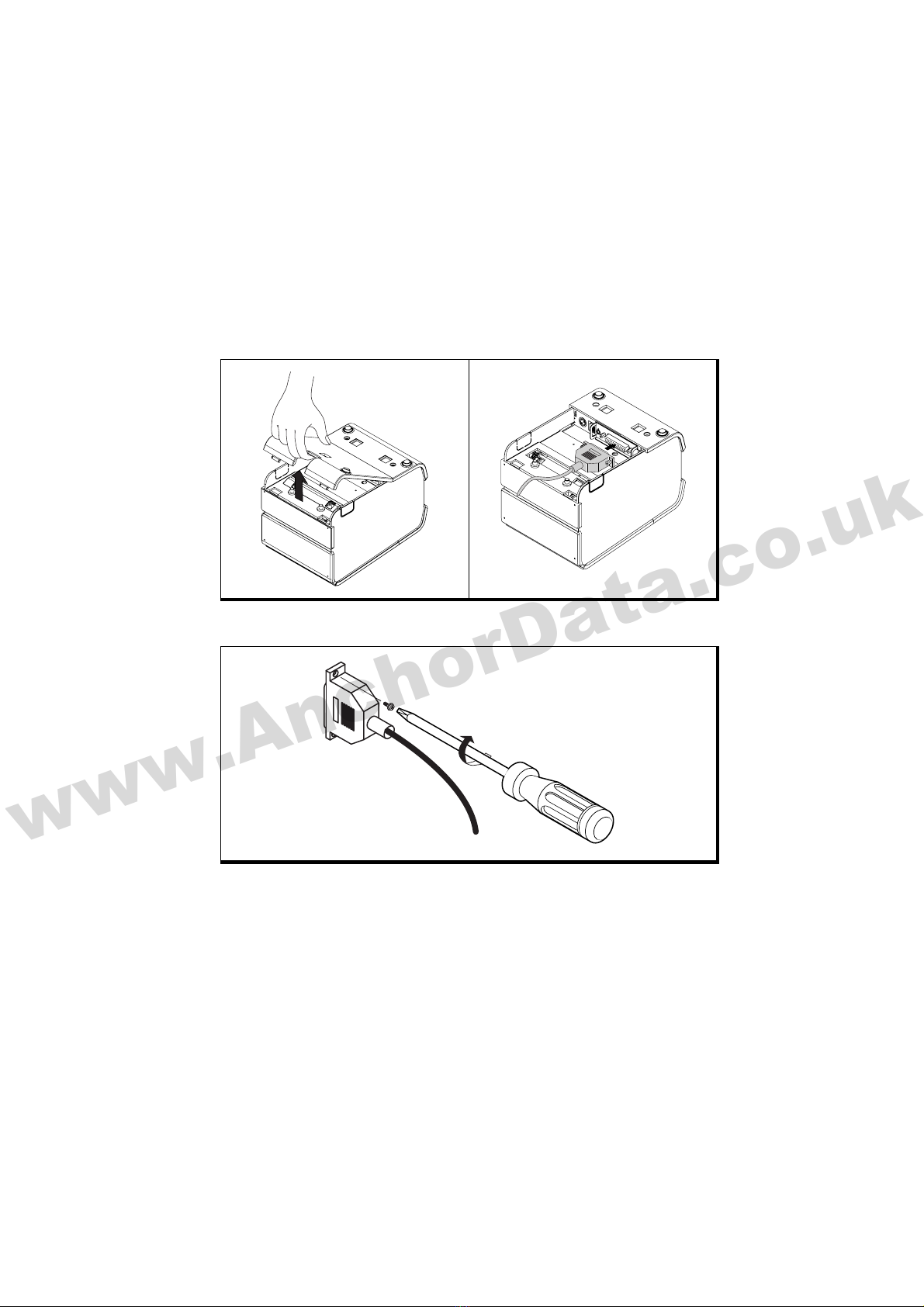
1-5. Connecting the Power Supply
Use the optional Power supply for your printer.
WARNING:
Make sure that you use the attached Power supply or equivalent. Using an incorrect power
supply may cause fire or electrical shock.
CAUTIONS:
When connecting or disconnecting the power supply from the printer, make sure that the
power supply is not plugged into an electrical outlet. Otherwise you may damage the
power supply or the printer.
If the power supply’s rated voltage and your outlet’s voltage do not match, contact your
dealer for assistance. Do not plug in the power cord. Otherwise, you may damage the
power supply or the printer.
1. Make sure the printer is turned off.
2. Pull the hole of the Cover-Wire to separate from the printer.
3. Plug the DC cord connector into the power jack on the printer.
4. If it is necessary to connect the interface, plug the interface connector into the
interface port on the printer.
5. If it is necessary to connect the drawer, plug the drawer connector into the drawer
port on the printer.
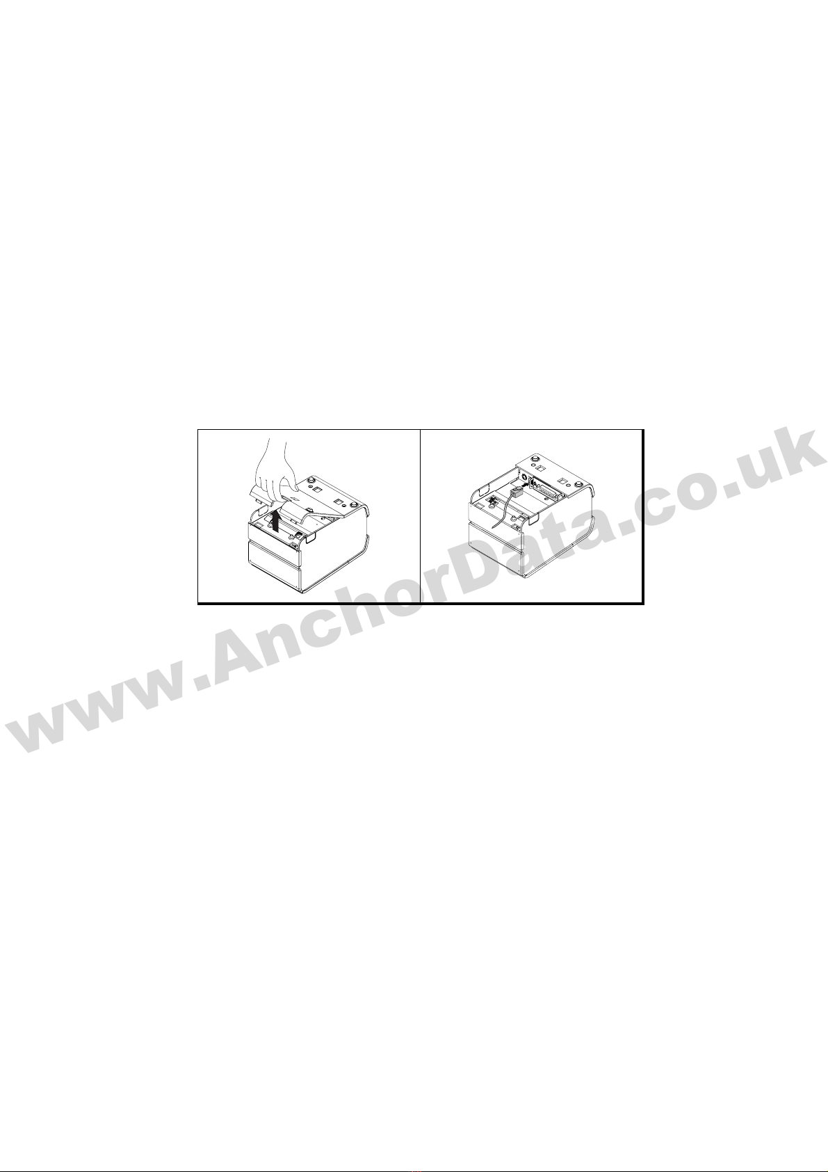
6. Put the two hooks into the two holes of the Case-Lower backward and close the
Cover-Wire until it locks firmly.
7. Plug the AC Adapter power cord into the wall outlet.
NOTES : If you want turn the ELLIX20 off, press and hold the powe
r
button about four seconds until the POWER LED is off.
NOTES : To remove the DC cable connector, make sure that the
power supply’s power cord is unplugged; then grasp the
connector at the arrow and pull it straight out.
www.AnchorData.co.uk

ٻڈٻ9ٻڈ
12
34
56
78
www.AnchorData.co.uk

ٻڈٻ10ٻڈ
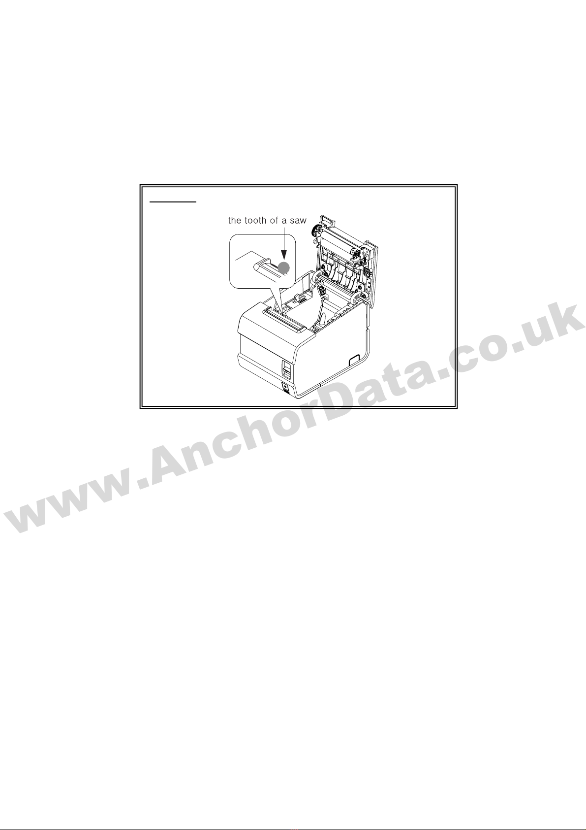
1-6. Installing or Replacing the Paper Roll
ٻ
ٻ
CAUTION : Be careful the manual cutter.
www.AnchorData.co.uk

ٻڈٻ11ٻڈ
1-6-1. Partition Installation
ٻ
ٻ
You can install the partition for 58mm paper printing on ELLIX20.
1. Push the Open-Button and open the Cover-Open.
2. Insert the Partition into the Paper-Supply as shown.
3. Push the Partition until the two hook locks firmly.
NOTES : The Paper partition is factory option item.
www.AnchorData.co.uk

ٻڈٻ12ٻڈ
1-6-2. Wall Mount Installation
1. Drill the wall to make the three holes and put the three anchors ཿinto the each hole.
(Notice the position of the holes.)
2. Tighten the three screws ྀinto the each anchor to fix the BRKT-Wall to the wall as
shown.
3. Hang the printer on the three hooks and fix it down.
ٻ
ٻ
ٻ
NOTES : Wall mount bracket is factory option item.
www.AnchorData.co.uk

ٻڈٻ13ٻڈ
1-6-3. Paper Roll Installation
1. Open the paper roll cover by pressing the cover-open button. If the cover-open button
will not open the cover, see page 3-4 or 3-6 in Troubleshooting.
2. Remove the used paper roll core if there is one.
3. Insert the paper roll as shown.
4. Be sure to note the correct direction that the paper comes off the roll.
5. Pull out a small amount of paper, as shown. Then close the cover.
6. Tear off the paper as shown.
NOTES : Be sure to use paper rolls that meet the specifications. Do
not use paper rolls that have the paper glued to the core
because the printer cannot detect the paper end correctly.
www.AnchorData.co.uk

ٻڈٻ14ٻڈ
1-7. Adjustments and Settings
The ELLIX 20 is set up at the factory to be appropriate for almost all users. It does,
however, offer some settings for users with special requirements.
It has DIP switches that allow you to change communication settings, such as handshaking
and parity check, as well as printing density.
The ELLIX 20 also has a near-end sensor for the paper. This can give you a warning when
the paper is almost out. If you find that there is not enough paper remaining on the roll
when the near-end detector is triggered, you can change the near-end sensor setting.
See the next page if you need to make any of these changes.
www.AnchorData.co.uk

ٻڈٻ15ٻڈ
1-7-1. Serial Interface Specification
DIP Switch Set 1 Functions
ٻ
SW FUNCTION ON OFF DEFAULT
1HandShaking XON/XOFF DSR/DTR OFF
2Word Length 7Bit 8Bit OFF
3Parity Check Yes No OFF
4Parity Selection EVEN ODD OFF
5OFF
6OFF
7
Baud rate selection Refer to the Following Table
OFF
8Dip Switch Select Dip Switch 2 Dip Switch 1 -
Baud rate selection
Transmission speed SW – 5 SW – 6 SW – 7 Remark
2400 baud ON ON ON -
4800 baud ON ON OFF -
9600 baud ON OFF ON -
14400 baud ON OFF OFF -
19200 baud OFF ON ON -
38400 baud OFF ON OFF -
57600 baud OFF OFF ON -
115200 baud OFF OFF OFF Default
Dip Switch Set 2 Functions
SW FUNCTION ON OFF DEFAULT
1Mode Selection STAR EPSON OFF
2*Kitchen Bell Enable Disable OFF
3Auto Cutter Disable Enable OFF
4Self Test Hexa Dump SelfTest Mode OFF
5OFF
6Select Print Density Refer to the Following Table OFF
7Data Receive Error Ignore Print “?” OFF
8Dip Switch Select Dip Switch 2 Dip Switch 1 -
*Kitchen Bell is option.
Print Density
Print Density SW - 5 SW – 6 Remark
1 ( Light ) ON ON -
2OFF OFF Default
3ON OFF -
4 ( Dark ) OFF ON -
www.AnchorData.co.uk

ٻڈٻ16ٻڈ
1-7-2. Parallel Interface Specification
Dip Switch Set 1 Functions
SW FUNCTION ON OFF DEFAULT
1Reserved - - -
2Reserved - - -
3Reserved - - -
4Reserved - - -
5Reserved - - -
6Reserved - - -
7Reserved - - -
8Dip Switch Select Dip Switch 2 Dip Switch 1 -
Dip Switch Set 2 Functions
SW FUNCTION ON OFF DEFAULT
1Mode Selection STAR EPSON OFF
2*Kitchen Bell Enable Disable OFF
3Auto Cutter Disable Enable OFF
4Self Test Hexa Dump SelfTest Mode OFF
5OFF
6Select Print Density Refer to the Following Table OFF
7Data Receive Error Ignore Print “?” OFF
8Dip Switch Select Dip Switch 2 Dip Switch 1 -
*Kitchen Bell is option.
Print Density
Print Density SW - 5 SW – 6 Remark
1 ( Light ) ON ON -
2OFF OFF Default
3ON OFF -
4 ( Dark ) OFF ON -
www.AnchorData.co.uk

ٻڈٻ17ٻڈ
1-8. Using the Printer
You can control the basic paper feeding operations of the printer with the button on the
control panel. The indicator lights help you monitor the printer’s status.
1-8-1. Control Panel
zFeed Button
The button can be disabled by the ESC c 5 command.
Press the FEED button once to advance paper one line. You can also hold down the FEED
button to feed paper continuously.
zPanel lights : LED (Color)
POWER (GREEN)
The POWER light is “ON” whenever the printer is “ON”.
ERROR (RED)
This indicates an error. See APPENDIX F<Page 48> for information of what to do when
this light comes on.
NO PAPER (RED)
This light indicates the near end of the paper roll. Install a new paper roll and the printer
will continue printing.
When the light blinks, it indicates the self-test printing standby state or macro execution
standby state when the macro execution command is used.
www.AnchorData.co.uk

ٻڈٻ18ٻڈ
Chapter 2. Hexadecimal Dumping
This feature allows the experienced users to see exactly what data is coming to the printer.
This can be useful in finding software problems. When you turn on the hexadecimal dump
function, the printer prints all commands and data in hexadecimal format along with a
guide section to help you find specific commands.
To use the hexadecimal dump function, follow these steps:
1. After you make sure that the printer is off.
2. Make sure DIP switch 2-4 to ON for Hexadecimal dumping mode.
3. Turn on the power while pressing the FEED button or executing GS ( A command;
then the printer prints “HEXADECIMAL DUMP MODE …” on the paper roll and enter
the hexadecimal dump mode..
4. Run any software program that sends data to the printer. The printer will print all the
codes it receives in a two-column format. The first column contains the hexadecimal
codes and the second column gives the ASCII characters that correspond to the
codes.
HEXADECIMAL DUMP MODE
PRESS PAPER FEED BUTTON THREE
TIMES TO EXIT DUMP MODE
1D 57 00 02 1D 48 02 42 61 72 . W . . . H . B a r
43 6F 64 65 20 50 72 69 6E 74 C o d e P r i n t
69 6E 67 0A 0A 1D 6B 00 31 32 i n g . . . K . 1 2
zA period (.) is printed for each code that has no ASCII equivalent.
zDuring the hex dump, all commands except DLE EOT and DLE ENQ are
disabled.
5. When the printing finishes, turn off the printer or press the FEED button three times,
and then change DIP switch 2-4 to OFF (Self-Test mode).
6. Turn on the printer and then the hexadecimal mode is off.
www.AnchorData.co.uk

ٻڈٻ19ٻڈ
Chapter 3. The self test
The self-test checks whether the printer has any problems. If the printer does not function
properly, contact your dealer. The self-test checks are as follows;
1. Make sure paper roll has been installed properly.
2. Turn on the power while holding down the FEED button. The self-test begins.
3. The self-test prints the current printer status, which provides the control ROM
version and the DIP switch setting.
4. After printing the current printer status, self-test printing will print the following, and
pause (The PAPER LED light blinks).
SELFTESTPRINTING.
PLEASE PRESS PAPER FEED BUTTON.
5. Press the FEED button to continue printing. The printer prints a pattern using the
built-in character set.
6. The self-test automatically ends and cuts the paper after printing the following.
**EndSelf-Test**
The printer is ready to receive data as soon as it completes the self-test.
www.AnchorData.co.uk

ٻڈٻ20ٻڈ
Chapter 4. Code Table
The following pages show the character code tables. To find the character corresponding
to a hexadecimal number, count across the top of the table for the left digit and count
down the left column of the table for the right digit. For example, 4A = J.
Page 0
( PC437 : USA, Standard Europe)
( International Character Set : USA )
HEX
HEX BIN
0 16 32 48 64 80 96 112 128 144 160 176 192 208 224 240
1 17 33 49 65 81 97 113 129 145 161 177 193 209 225 241
2 18 34 50 66 82 98 114 130 146 162 178 194 210 226 242
3 19 35 51 67 83 99 115 131 147 163 179 195 211 227 243
4 20 36 52 68 84 100 116 132 148 164 180 196 212 228 244
5 21 37 53 69 85 101 117 133 149 165 181 197 213 229 245
6 22 38 54 70 86 102 118 134 150 166 182 198 214 230 246
7 23 39 55 71 87 103 119 135 151 167 183 199 215 231 247
8 24 40 56 72 88 104 120 136 152 168 184 200 216 232 248
9 25 41 57 73 89 105 121 137 153 169 185 201 217 233 249
10 26 42 58 74 90 106 122 138 154 170 186 202 218 234 250
11 27 43 59 75 91 107 123 139 155 171 187 203 219 235 251
12 28 44 60 76 92 108 124 140 156 172 188 204 220 236 252
13 29 45 61 77 93 109 125 141 157 173 189 205 221 237 253
14 30 46 62 78 94 110 126 142 158 174 190 206 222 238 254
15 31 47 63 79 95 111 127 143 159 175 191 207 223 239 255
89ABCDEF
1000 1001 1010 1011 1100 1101 1110 1111
00000
Ç
NUL DLE
0@P ` áųŊ
ʼn
إ
ő
ŭ
Ũ
ŵŎ
10001
üíŴŏ
20010
éó"2
ņ
30011
âúŇŌ
40100
äō
50101
Ő
EOT DC4
$4DT
Ŝ
ş
Š
ś
ŕ
Ū
ŧ
60110
آ
ŝ
70111
81000
91001
»
Ţ
ţ
ŗ
Ŗ
Ť
Œ
Ř
¡
«
½
ό
ƒ
ñ
Ñ
ª
º
¿
Ń
¬
¥
ķ
A1010
C1100
¢
γ
B1011
ù
ÿ
Ö
Ü
D1101
Å
É
æ
Æ
ô
ö
ò
û
1110
Ͼ
ì
Ä
FF FS
ͽ
F1111
à
å
ê
ê
ë
è
ï
E
45670123
0000 0001 0010 0011 0100 0101 0110 0111
p
XON
!1AQaq
BRb r
X
OF
F
#3CScs
dt
ENQ
%5 EU e u
&6FV f v
'7GWgw
CAN
(8HXhx
HT
)9IYiy
LF
*:JZjz
ESC
+;K[k{
Ν έ
CR GS
-=M]m}
.>N^n~
/?O_o
ũ
ť
Ŧ
Ś
ř
œ
Ŕ
Ŭ
ū
ŋ
ň
Ű
س
ű
Ų
Ů
Į
ß
ī
ʌ
Ȉ
ı
μ
IJ
ĭ
Ĭ
ȍ
į
ij
İ
ŀ
Ł
±
ń
Ņ
÷
§
°
·
·
¥
ס
²
Ŷ
www.AnchorData.co.uk
Other manuals for ELLIX 20
1
Table of contents
Other Sam4s Printer manuals