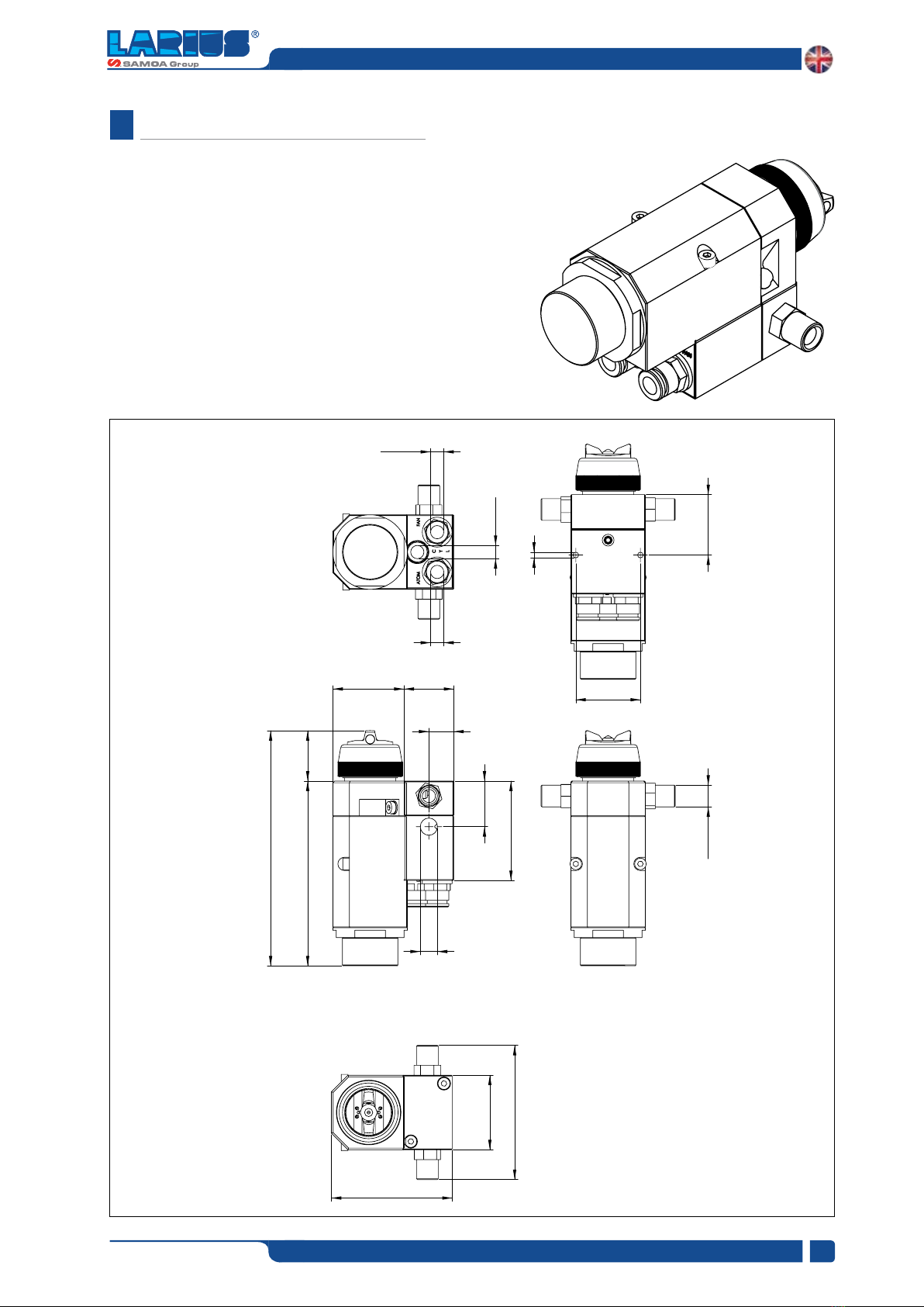
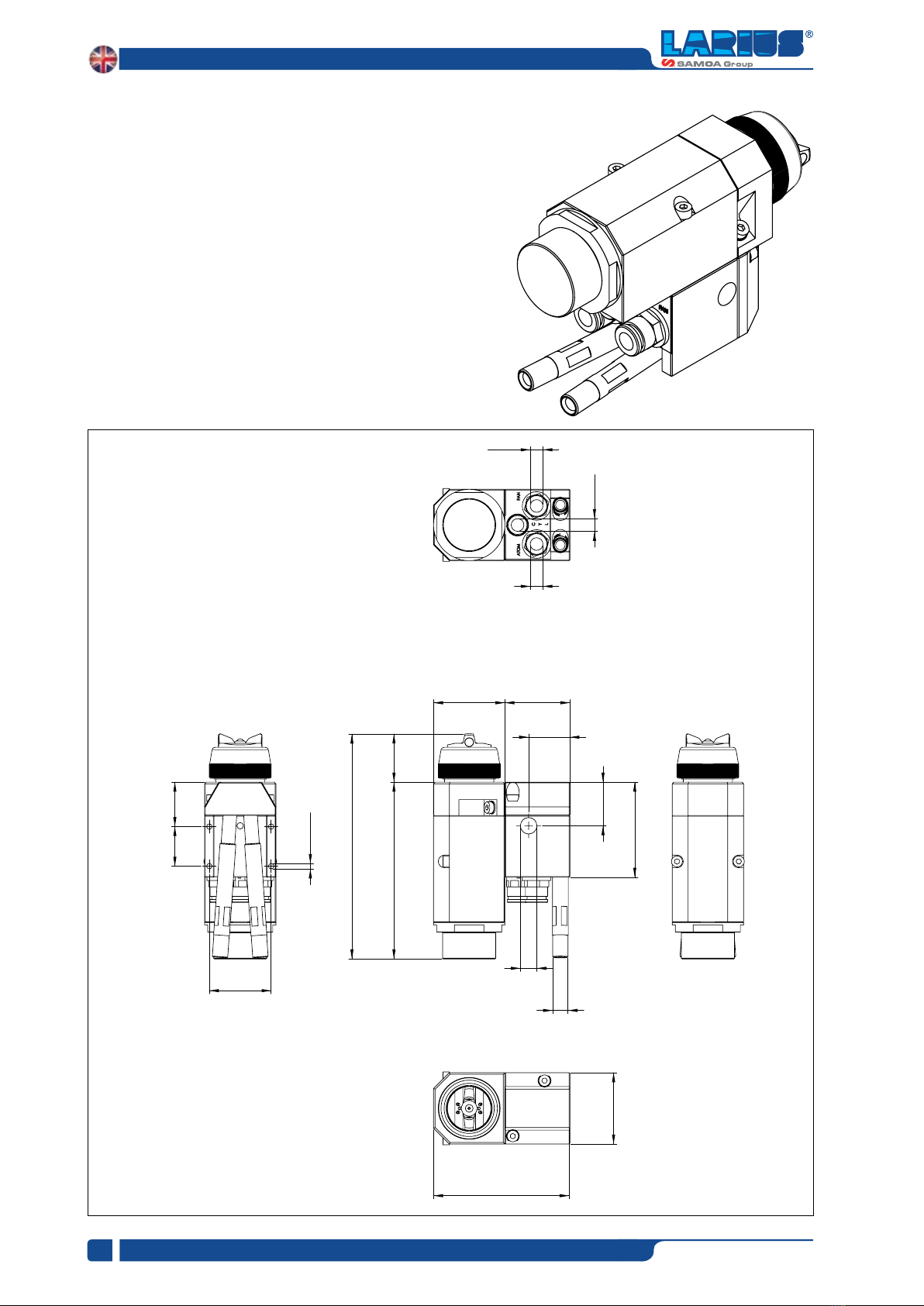
Samoa Larius L200 User manual

L200
INOX version
ALLUMINIUM version
L201
INOX version
ALLUMINIUM version
Automatic guns
Air assisted airless
www.larius.com
REV. 01 - 01/2020
Cod. 150084
English
OPERATING INSTRUCTIONS

www.larius.com
2
L200 - L201
REV. 01 - 01/2020 - Cod. 150084
Larius S.r.l, founded in 1969, designs and manufactures painting equipment, and transfer
and extrusion pumps.
Larius S.r.l is a company with a great industrial tradition and an innovative technological
culture.
Internal production, based on innovation and research, is flexible to industry changes in order
to achieve the primary objective of creating value.
Larius S.r.l is the only leading Italian company in the international market. The brand is
distributed worldwide, through an extensive network of distributors and resellers, and is a
guarantee of Total Product Quality in the industrial, plastics, construction, wood and road
marking sectors.
Due to a constant product improvement programme, the factory reserves the right to modify
technical details mentioned in this manual without prior notice.
This manual is to be considered as an English language translation of the original manual in Italian.
The manufacturer shall bear no responsibility for any damages or inconveniences that may arise due to
the incorrect translation of the instructions contained within the original manual in Italian.

www.larius.com
3
L200 - L201
REV. 01 - 01/2020 - Cod. 150084
L200 - L201
Air assisted airless automatic spray guns
WARNINGS ............................................................................................................................................................ p. 4
VERSIONS.............................................................................................................................................................. p. 5
WORKING PRINCIPLE ........................................................................................................................................... p. 6
TECHNICAL CHARACTERISTICS.......................................................................................................................... p. 7
ATEx CERTIFICATE ................................................................................................................................................ p. 8
DIMENSIONS AND OVERALL................................................................................................................................ p. 9
TRANSPORT AND UNPACKING ............................................................................................................................ p.11
SAFETY RULES...................................................................................................................................................... p.11
DESCRIPTION OF THE EQUIPMENT .................................................................................................................... p.13
FLUID INJECTION HAZARD .................................................................................................................................. p.14
EQUIPMENT MISUSE HAZARD............................................................................................................................. p.14
FEED HOSE SAFETY ............................................................................................................................................. P. 14
FIRE OR ExPLOSION HAZARD ............................................................................................................................. p.15
MOVING PARTS HAZARD...................................................................................................................................... p.15
CONDITIONS OF GUARANTEE ............................................................................................................................. p.15
FLUID CIRCUIT INSTALLATION AND CONNECTION ............................................................................................ p.16
FLUID SYSTEM CONNECTION ............................................................................................................................. p.17
PNEUMATIC SYSTEM CONNECTION ............................................................................................................... p.18
ExPLODED VIEW OF THE L200 - L201 AUTOMATIC GUN ................................................................................ p.20
ExPLODED VIEW OF THE BLOCK WITH SIDE INLETS L200 ............................................................................ p.22
ExPLODED VIEW OF THE BLOCK WITH REAR INLETS L201 ........................................................................... p.23
AIR ASSISTED AIRLESS NOZZLES ....................................................................................................................... p.24
SUPER FAST-CLEAN NOZZLES ............................................................................................................................ p.25
TROUBLESHOOTING ............................................................................................................................................ p.26
GUNS RANGE ........................................................................................................................................................ p.28
A
C
D
B
E
H
G
F
I
M
N
J
k
L
O
P
Q
R
S
T
U
V
W
x
WE ADVISE THE USE OF THIS EQUIPMENT ONLY BY PROFESSIONAL OPERATORS.
ONLY USE THIS MACHINE FOR USAGE SPECIFICALLY MENTIONED IN THIS MANUAL.
Thank you for choosing a LARIUS S.R.L. product.
As well as the product purchased, you will receive a range of support services
enabling you to achieve the results desired, quickly and professionally.

www.larius.com
4
L200 - L201
REV. 01 - 01/2020 - Cod. 150084
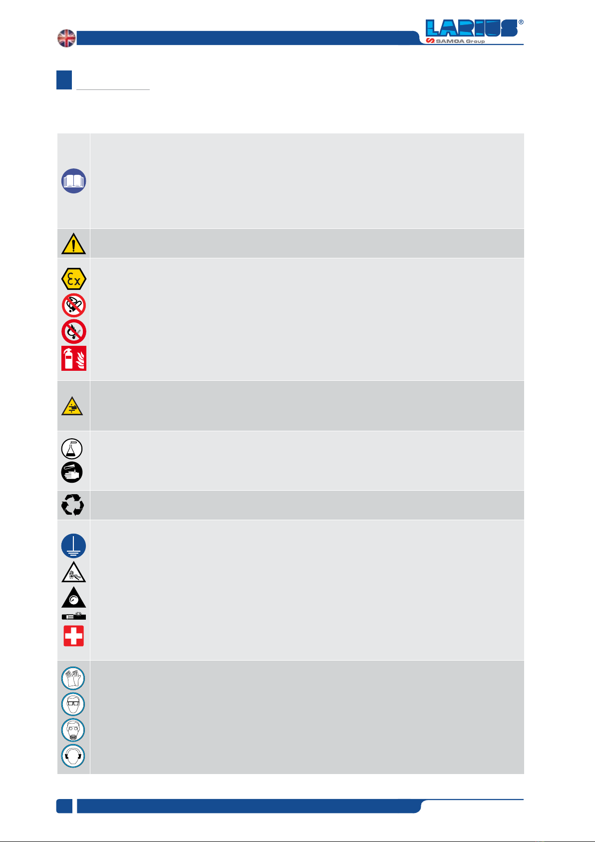
The table below provides the meaning of the symbols used in this manual in relation to using, earthing, operating, maintaining, and
repairing of this equipment.
WARNINGS
A
• Read this operator’s manual carefully before using the equipment.
• An improper use of this machine can cause injuries to people or things.
• Do not use this machine when under the inuence of drugs or alcohol.
• Do not modify the equipment under any circumstances.
• Use products and solvents that are compatible with the various parts of the equipment, and read the manufacturer’s warnings carefully.
• See the Technical Details for the equipment given in the Manual.
• Check the equipment for worn parts once a day. If any worn parts are found, replace them using ONLY original spare parts.
• Keep children and animals away from work area.
• Comply with all safety standards.
• It indicates an accident risk or serious damage to equipment if this warning is not followed.
FIRE AND EXPLOSION HAZARD
• Solvent and paint fumes in work area can ignite or explode.
• To help prevent fire and explosion:
- Use equipment ONLY in well ventilated area.
- Eliminate all ignition sources, such as pilot lights, cigarettes and plastic drop cloths (potential static arc).
- Ground equipment and conductive objects.
- Use only grounded hoses.
- Do not use trichloroethane, methylene chloride, other halogenated hydrocarbon solvents or uids containing such solvents in
pressurized aluminium equipment. Such use can cause serious chemical reaction and equipment rupture, and result in death,
serious injury, and property damage.
- Do not form connections or switch light switches on or off if the air contains inammable fumes.
• If electrical shocks or discharges are encountered the operation being carried out using the equipment must be stopped immediately.
• Keep a re extinguisher at hand in the immediate vicinity of the work area.
• It indicates wound and nger squashing risk due to movable parts in the equipment.
• Tenersi lontano dalle parti in movimento.
• Do not use the equipment without the proper protection.
• Before any inspection or maintenance of the equipment, carry out the decompression procedure explained in this manual, and prevent
any risk of the equipment starting unexpectedly.
• Report any risk of chemical reaction or explosion if this warning has not been given.
• (IF PROVIDED) There is a risk of injury or serious lesion related to contact with the jet from the spray gun. If this should occur, IMME-
DIATELY contact a doctor, indicating the type of product injected.
• (IF PROVIDED) Do not spray before the guard has been placed over the nozzle and the trigger on the spray gun.
• (IF PROVIDED) Do not put your ngers in the spray gun nozzle.
• Once work has been completed, before carrying out any maintenance, complete the decompression procedure.
• It indicates important recommendations about disposal and recycling process of products in accordance with the environmental
regulations.
• Mark any clamps attached to earth cables.
• Use ONLY 3-wire extension cords and grounded electrical outlets.
• Before starting work make sure that the electrical system is earthed and that it complies with safety standards.
• High-pressure uid from gun, hose leaks, or ruptured components will pierce skin.
• To help prevent injection, always:
- (IF PROVIDED) Engage trigger lock when not spraying.
- (IF PROVIDED) Do not put your hand over the spray tip. Do not stop or deect leaks with your hand, body or other.
- (IF PROVIDED) Do not point gun at anyone or at any part of the body.
- (IF PROVIDED) Never spray without tip guard.
- Do pressure relief if you stop spraying or being servicing sprayer and before any maintenance operations.
- Do not use components rated less than sprayer Maximum Working Pressure.
- Never allow children to use this unit
- (IF PROVIDED) Brace yourself; gun may recoil when triggered.
If high pressure fluid pierces your skin, the injury might look like “just a cut”, but it is a serious wound!
Get immediate medical attention.
• It is obligatory to wear suitable clothing as gloves, goggles and face shield.
• Wear clothing that complies with the safety standards in force in the country in which the equipment is used.
• Do not wear bracelets, earrings, rings, chains, or anything else that may hinder the operator’s work.
• Do not wear clothing with wide sleeves, scarves, ties, or any other piece of clothing that could get tangled up in moving parts of the
equipment during the work, inspection, or maintenance cycles.

L200 - L201 AIR ASSISTED AIRLESS AUTOMATIC SPRAY GUN - ALLUMINIUM VERSION
COD. 21345 COD. 21346
Code Description
21345 L200 Air assisted airless automatic spray gun. With side inlets. For Air assisted airless nozzles.
21344 L200 Air assisted airless automatic spray gun. With side inlets. Complete with Mist-Clean 2 base for Super Fast Clean or
Top Spraying Clean nozzles.
21346 L201 Air assisted airless automatic spray gun. With rear inlets. For Air assisted airless nozzles.
21347 L201 Air assisted airless automatic spray gun. With rear inlets. Complete with Mist-Clean 2 base for Super Fast Clean or
Top Spraying Clean nozzles.
www.larius.com
5
L200 - L201
REV. 01 - 01/2020 - Cod. 150084
B
COD. 21340 COD. 21341
COD. 21342 COD. 21343
VERSIONS
Code Description
21340 L200 Air assisted airless automatic spray gun. With side inlets. For air assisted airless nozzles.
21342 L200 Air assisted airless automatic spray gun. With side inlets. Complete with Mist-Clean 2 base for Super Fast Clean or Top
Spraying Clean nozzles.
21341 L201 Air assisted airless automatic spray gun. With rear inlets. For Air assisted airless nozzles.
21343 L201 Air assisted airless automatic spray gun. With rear inlets. Complete with Mist-Clean 2 base for Super Fast Clean or Top
Spraying Clean nozzles.
L200-L201 AIR ASSISTED AIRLESS AUTOMATIC SPRAY GUN - INOX VERSION

www.larius.com
6
L200 - L201
REV. 01 - 01/2020 - Cod. 150084
WORKING PRINCIPLE
C
The L200-L201 automatic spray guns optimize performance for painting metal and wood; all of the parts in contact with the product
are made of stainless steel to ensure a longer life and resistance over time. Characterised by the ease of mounting and removing
components for maintenance.
The spray guns allow you to:
• open or close the product recirculation valve;
• choose between the two product inlet bases. The two bases are completely interchangeable without having to make changes
to the body of the spray gun;
• rapid couplings to speed up the connection of the spray gun to the air supply line;
• a high precision cap for adjusting the product passage inlet is provided.
The Air assisted airless gun has a closing spring that allows it to operate with a max operating pressure of 110 bar.
To operate with the 140 bar max pressure you must install the “reinforced” spring that you will nd in the case.
60 lt.
PRODUCT
PRODUCT
SUPPLY
AIR SUPPLY
RECIRCULATION
NOTE:
Recommended air atomization 0,2 ÷ 1 bar (max)
Recommended air fan 0,2 ÷ 1 bar (max)
L200 -L201
Automatic Gun

www.larius.com
7
L200 - L201
REV. 01 - 01/2020 - Cod. 150084
TECHNICAL CHARACTERISTICS
D
Maximum fluid pressure 250 bar (25 MPa)
Maximum working air pressure 7 bar (0,7 Mpa)
Maximum cylinder air pressure 7 bar (0,7 MPa)
Minimum actuating pressure 3,5 bar (0,3 Mpa)
Maximum working fluid temperature 50° C
Wetted parts
stainless steel/alluminium
carbide
polyethylene
chemically resistant fluoroelastomer
PTFE
Material in contact with fluid
alluminium
POM
flluoroelastomer
Guns weight L200: 1100 g - L200/Avional: 770 g
L201: 1230 g - L201/Avional: 900 g
Air inlet:
Atomization 1/4” - tube 8x6
Fan 1/4” - tube 8x6
Opening gun 1/8” - tube 8x6
Fluid inlet L200: 1/4”
L201: 1/8”
Dimensions (exluiding fittings) L200: L: 140 mm - P: 45 mm - H: 75 mm
L201: L: 140 mm - P: 45 mm - H: 90 mm
Working pressures recommended for the air:
Air atomization 0,2 ÷ 1 bar (max)
Air fan 0,2 ÷ 1 bar (max)

www.larius.com
8
L200 - L201
REV. 01 - 01/2020 - Cod. 150084
D.a - ATEX CERTIFICATE

www.larius.com
9
L200 - L201
REV. 01 - 01/2020 - Cod. 150084
E.a - DIMENSIONS AND OVERALL L200 GUN
DIMENSIONS AND OVERALL
E
60
30 43
112
142
30
15
27.5
Ø10.4
Ø8X6
Ø8X6
Ø8X6
GJ 1/4
39
36.5
M4X10
73
45
81

www.larius.com
10
L200 - L201
REV. 01 - 01/2020 - Cod. 150084
E.b - DIMENSIONS AND OVERALL L201 GUN
60
4145
112
142
30
27.5
26
Ø10.4
Gj 1/8
Ø8X6
Ø8X6
Ø8X6
45
85.5
39
25 28
M4X10

www.larius.com
11
L200 - L201
REV. 01 - 01/2020 - Cod. 150084
• THE EMPLOYER SHALL TRAIN ITS EMPLOYEES
ABOUT ALL THOSE RISKS STEMMING
FROM ACCIDENTS, ABOUT THE USE OF SAFETY
DEVICES FOR THEIR OWN SAFETY AND ABOUT
THE GENERAL RULES FOR ACCIDENT
PREVENTION IN COMPLIANCE WITH
INTERNATIONAL REGULATIONS AND WITH THE LAWS OF
THE COUNTRY WHERE THE PLANT IS USED.
• THE BEHAVIOUR OF THE EMPLOYEES SHALL
STRICTLY COMPLY WITH THE ACCIDENT
PREVENTION AND ALSO ENVIRONMENTAL
REGULATIONS IN FORCE IN THE COUNTRY WHERE THE
PLANT IS INSTALLED AND USED.
• KEEP YOUR WORK PLACE CLEAN AND TIDY.
DISORDER WHERE YOU ARE WORKING CREATES A
POTENTIAL RISK OF ACCIDENTS.
• The manufacturer will not be responsible for the unloading
operations and transport to the workplace of the machine.
• Check the packing is undamaged on receipt of the equipment.
Unpack the machine and verify if there has been any damage
due to transportation.
In case of damage, call immediately LARIUS and the Shipping
Agent. All the notices about possible damage or
anomalies must arrive timely within 8 days at least from the
date of receipt of the plant through Registered Letter to the
Shipping Agent and to LARIUS.
• ALWAYS KEEP PROPER BALANCE AVOIDING UNUSUAL
STANCE.
• BEFORE USING THE TOOL, ENSURE THERE ARE NOT
DAMAGED PARTS AND THE MACHINE CAN WORK PROPERLY.
• ALWAYS FOLLOW THE INSTRUCTIONS ABOUT SAFETY AND
THE REGULATIONS IN FORCE.
• KEEP THOSE WHO ARE NOT RESPONSIBLE FOR THE
EQUIPMENT OUT OF THE WORK AREA.
• NEVER EXCEED THE MAXIMUM WORKING
PRESSURE INDICATED .
• NEVER POINT THE SPRAY GUN AT YOURSELVES
OR AT OTHER PEOPLE. THE CONTACT WITH
THE CASTING CAN CAUSE SERIOUS INJURIES.
• IN CASE OF INJURIES CAUSED BY THE GUN
CASTING, SEEK IMMEDIATE MEDICAL ADVICE
SPECIFYING THE TYPE OF THE PRODUCT
INJECTED. NEVER UNDERVALUE A WOUND
CAUSED BY THE INJECTION OF A FLUID.
• ALWAYS DISCONNECT THE SUPPLY AND
RELEASE THE PRESSURE IN THE CIRCUIT
BEFORE PERFORMING ANY CHECK OR PART
REPLACEMENT OF THE EQUIPMENT .
• NEVER MODIFY ANY PART IN THE EQUIPMENT.
CHECK REGULARLY THE COMPONENTS OF THE SYSTEM.
REPLACE THE PARTS DAMAGED OR WORN.
• TIGHTEN AND CHECK ALL THE FITTINGS FOR
CONNECTION BETWEEN PUMP, FLExIBLE HOSE
AND SPRAY GUN BEFORE USING THE EQUIPMENT.
• ALWAYS USE THE FLEXIBLE HOSE SUPPLIED WITH
STANDARD KIT. THE USE OF ANY ACCESSORIES OR
TOOLING OTHER THAN THOSE RECOMMENDED
IN THIS MANUAL, MAY CAUSE DAMAGE OR
INJURE THE OPERATOR.
• THE FLUID CONTAINED IN THE FLEXIBLE
HOSE CAN BE VERY DANGEROUS.
HANDLE THE FLExIBLE HOSE CAREFULLY.
DO NOT PULL THE FLExIBLE HOSE TO MOVE
THE EQUIPMENT. NEVER USE A DAMAGED OR
A REPAIRED FLExIBLE HOSE.
TRANSPORT AND
UNPACKING
F
The disposal of packaging materials is a
customer’s competence and must be performed
in accordance with the regulations in force in the
country where the plant is installed and used.
It is nevertheless sound practice to recycle
packaging materials in an environment-friendly
manner as much as possible.
SAFETY RULES
G
Read carefully and entirely the following
instructions before using the product.
Please save these instructions in a safe place.
The unauthorised tampering/replacement of one
or more parts composing the machine, the use
of accessories, tools, expendable materials other
than those recommended by the manufacturer
can be a danger of accident.
The manufacturer will be relieved from tort and
criminal liability.

www.larius.com
12
L200 - L201
REV. 01 - 01/2020 - Cod. 150084
IF THE PRODUCT TO BE USED IS TOXIC, AVOID
INHALATION AND CONTACT BY USING PRO-
TECTION GLOVES, GOGGLES AND PROPER
FACE SHIELDS.
TAKE PROPER SAFETY MEASURES FOR THE
PROTECTION OF HEARING IN CASE OF WORK
NEAR THE PLANT.
The high speed of the product in the hose can
create static electricity through discharges and
sparks. It is suggested to earth the equipment.
The pump is earthed through the earth cable of
the supply.
The gun is earthed through the high pressure
flexible hose.
All the conductors near the work area must be
earthed.
Always check the product is compatible with the
materials composing the equipment (pump, spray
gun, flexible hose and accessories) with which it
can come into contact. Never use paints or sol-
vents containing halogen hydrocarbons (as the
methylene chloride).
If these products come into contact with alu-
minium parts can provoke dangerous chemical
reactions with risk of corrosion and explosion.
DO NOT USE METAL TOOLS TO CLEAN THE NOZZLES,
SINCE THEY MAY BE SCRATCHED AND CAUSE
UNEVEN SPRAYING.
DO NOT IMMERSE THE SPRAYGUN IN SOLVENT.
DO NOT POINT THE GUN UPWARDS
DURING CLEANING OPERATIONS.
DO NOT RUB THE SPRAYGUN WITH CLOTHS
SOAKED IN SOLVENT.
• NEVER SPRAY OVER FLAMMABLE PRODUCTS OR
SOLVENTS IN CLOSED PLACES.
• NEVER USE THE TOOLING IN PRESENCE OF POTENTIALLY
ExPLOSIVE GAS.
• USE EXTREME CAUTION WHEN CLEANING OR CHANGING
THE FLUID NOZZLE. IF THE NOZZLE CLOGS WHILE
DISPENSING, FULLY RELEASE THE TRIGGER IMMEDIATELY.
ALWAYS FOLLOW THE PRESSURE RELIEF PROCEDURE,
BELOW, BEFORE WIPING OFF BUILD-UP AROUND THE
NOZZLE OR REMOVING THE NOZZLE TO CLEAN IT.

www.larius.com
13
L200 - L201
REV. 01 - 01/2020 - Cod. 150084
L200 spray gun
L201 spray gun
DESCRIPTION OF THE EQUIPMENT
H
Pos. Description
1 Head
2 Locking ring nut
3 Gun body
4 Threaded cap for adjustment
Pos. Description
5 Air connections
6 Material in/out
7 Air inlet block
8 Product inlet block
3
2
1
8
4
5
6
6
7
3
2
1
6
6
8
5
7
4

www.larius.com
14
L200 - L201
REV. 01 - 01/2020 - Cod. 150084
The uid in the feed hose may be extremely hazardous. If there is
a leak from the hose or a cut or rupture due to wear or damage or
incorrect use, the uid that leaks out may cause uid penetration
damage or may seriously damage objects.
Any misuse of the dispensing equipment or accessories,
such as overpressurizing, modifying parts, using incompatible
chemicals and uids, or using worn or damaged parts, can
cause them to rupture and result in serious injury, including uid
injection and splashing uid in the eyes or on the skin, or in re,
explosion or property damage.
• Do not attempt to reconnect the feed hoses or repair them with
tape or any other method.
• Handle and route hoses carefully.
MEDICAL ALERT – FLUID INJECTION WOUNDS
If any uid appears to penetrate your skin, get EMERGENCY
MEDICAL CARE AT ONCE. DO NOT TREAT AS A SIMPLE CUT.
Tell the doctor exactly what uid was injected.
• Tighten all fluid connections securely before each use.
High pressure uid can dislodge a loose coupling or allow high
pressure uid to be emitted from the coupling
• Never use a damaged hose. If any of these conditions exist,
replace the hose immediately.
Proper hose grounding continuity is essential to maintaining a
grounded dispensing system. Check the electrical resistance of
your uid hoses at least once a week. If your hose does not have
a tag on it which species the maximum electrical resistance,
contact the hose supplier or manufacturer for the maximum
resistance limits.
Use a resistance meter in the appropriate range for your hose to
check the resistance. If the resistance exceeds the recommended
limits, replace it immediately. An ungrounded or poorly grounded
uid hose can make your system hazardous.
Be sure that all dispensing equipment and accessories are
properly rated to withstand the pressures developed by your
system. Never exceed the maximum working pressure of your
gun model.
J
Thefluidthatthespraygunshootmay penetratethe
skin and body causing severe damage, including
the need for amputation. Fluid that penetrates or
is sprayed into the eyes or onto the skin can also
cause serious injury.
Injection into the skin is a traumatic injury.
It is important to treat the injury surgically as
soon as possible. Do not delay treatment to
research toxicity.
Toxicity is a concern with some exotic materials
injected directly into the blood stream.
Consultation with a plastic surgeon may be
advisable.
EQUIPMENT MISUSE
HAZARD
J
The maximum working pressure of the gun is
280 bar. Do not exceed the maximum Working
pressure.
Do not place hands or fingers on the nozzle.
Do not clean the residues that form around the
nozzle until the pressure has been completely
discharged. Do not try and stop leaks with your
hands or body.
Be sure all fluids and solvents used are chemically
compatible with the “WETTED PARTS” shown in
the TECHNICAL DATA. Always read the fluid and
solvent manufacturer’s literature before using any
fluid or solvents in your system.
FLUID INJECTION HAZARD
I
Before each use, check the entire hose for cuts,
leaks, abrasion, bulging cover, or damage or
movement of the hose couplings.
Do not pull on hoses to move equipment.
Do not use fluids or solvents which are not
compatible with the inner tube and cover of the
hose.
Do not expose hose to extreme temperatures;
check with your hose supplier to determine
temperature tolerance.
K FLUID INJECTION HAZARD

www.larius.com
15
L200 - L201
REV. 01 - 01/2020 - Cod. 150084
FIRE OR EXPLOSION HAZARD
Static electricity is created by the ow of uid through the pump
and hose. If every part of the equipment is not properly grounded,
sparking may occur, and the system may become hazardous.
Sparks may also occur when plugging in or unplugging a power
supply cord. Sparks can ignite fumes from solvents and the uid
being dispensed, dust particles and other ammable substances,
whether you are pumping indoors or outdoors, and cause a re
or explosion, serious injury, and property damage.
GROUNDING
To reduce the risk of static sparking, ground the pump and
all other equipment used or located in the dispensing area.
Check your local electrical code for detailed grounding instructions
for your area and type of equipment and be sure to ground all of
the following equipment.
• Pump: ground the pump by connecting a grounding wire from
the pump’s grounding lug to a true earth ground.
• Air compressor or hydraulic power supply: ground according to
local code and manufacturer’s recommendations.
• Fluid hoses: use only grounded hoses with a maximum of 150
mt. Combined hose length to ensure grounding continuity.
Refer to hose grounding continuity, above.
• Flo-gun: obtain grounding through connection a properly
grounded uid hose and pump.
• Fluid supply container: according to local code.
• All solvent pails used when ushing: according to local code.
Use only metal pails. Do not place the pail on a non-conductive
surface, such as paper or cardboard, which interrupts the
grounding continuity.
Moving parts can pinch or amputate your ngers or other body
parts. Keep clear of moving parts when starting or operating
your system.
Before checking or servicing the gun, pump, or any other system
component follow the PRESSURE DISCHARGING PROCEDURE
to prevent the pump from starting accidentally.
Do not plug in or unplug any power supply cords
in the dispensing area when there is any chance
of igniting fumes still in the air.
If you experience any static sparking or feel even
a slight shock while using this equipment, STOP
DISPENSING IMMEDIATELY. Check for proper
grounding of the entire system. Do not use the
system again until the cause of the problem is
identified and corrected.
Before flushing, be sure the entire system and
flushing pails are properly grounded. Refer to
GROUNDING, above. Always use the lowest
possible fluid pressure, and maintain firm
metal-to-metal contact between the gun and
grounded metal pail during flushing to reduce
the risk of fluid injection injury, static sparking
and splashing.
CONDITIONS OF GUARANTEE
N
The conditions of guarantee do not apply in the
following situations:
- improper washing and cleaning of components
causing malfunction, wear or damage to the
equipment or any of its parts;
- improper use of the equipment;
- use that does not conform with applicable
national legislation;
- incorrect or faulty installation;
- modifications, interventions and maintenance
that have not been authorised by the
manufacturer;
- use of non-original spare parts or parts that do
not correspond to the specific model;
- total or partial non-compliance with the
instructions provided.
LMOVING PARTS HAZARD
M

www.larius.com
16
L200 - L201
REV. 01 - 01/2020 - Cod. 150084
PRODUCT
The illustration shows a typical example for creating a high pressure painting system with circulation system via L200/L201 automatic
spray gun.
The system can be completed and built with different solutions.
LARIUS is at your disposal to help design custom solutions with different production requirements.
NOTE:
This diagram is merely indicative and has no contractual value.
Pos. Description
1 L200 / L201 gun
2 Flow regulator LARIUS (Code 7000)
3 Gauge
4 Flow regulator LARIUS (Code 7030)
5 Filter
6 Pump
7 Product tank
O FLUID CIRCUIT INSTALLATION AND CONNECTION
L200/L201 GUN
SUPPLY
3 4 5
61
7
2
PRODUCT
RECIRCULATION

www.larius.com
17
L200 - L201
REV. 01 - 01/2020 - Cod. 150084
ENTRY RIGHT
ENTRY LEFT
RECIRCULATION
FLUID SYSTEM CONNECTION
P
FLUIDE
FLUIDE
FLUIDE
FLUIDE

www.larius.com
18
L200 - L201
REV. 01 - 01/2020 - Cod. 150084
PNEUMATIC SYSTEM CONNECTION
Q
L200
L201

This page is intentionally left blank
www.larius.com
19
L200 - L201
REV. 01 - 01/2020 - Cod. 150084

123456 78
9
10.A
11
12
14
15
19 20
21
1
7
23
24 25
16
27
28
26
10
29 30 31 32 33
34
38
36
39
13 3518 22
28
37
27
WARNING: Always indicate code and quantity for each part required.
EXPLODED VIEW OF L200-L201 AUTOMATIC GUN
R
www.larius.com
20
L200 - L201
REV. 01 - 01/2020 - Cod. 150084
This manual suits for next models
5
Table of contents
Other Samoa Paint Sprayer manuals

Samoa
Samoa Larius 2 Operating instructions

Samoa
Samoa Larius L100 User manual

Samoa
Samoa LARIUS Star 3001S User manual

Samoa
Samoa LARIUS L400 User manual

Samoa
Samoa 186 310 Operating manual

Samoa
Samoa Larius STAR 3001W Manual

Samoa
Samoa LARIUS GHIBLI 30:1 Operating instructions

Samoa
Samoa Larius GHIBLI SE 9000 User manual