6 | SAMLEX AMERICA INC.
SECTION 2 | Features, Applications &
Principle of Operation
•LowInterferenceTechnologyforcontrolledRFnoise•IdealforRV’s,Trucksandremotehousing2.3.1 Soft Start Technology
This feature offers the following advantages:
•WhentheInverterisswitchedON,thevoltagerampsupto115VACinaround2sec.If the load was already ON at the time of switching ON of the Inverter, starting surge
current demanded by certain reactive devices like motors etc. will be reduced and
there will be less likelihood of the Inverter shutting down due to overload.
•IftheInverterisswitchedONrstandthenaloadwithhigherstarting/inrushcur-
rent like SMPS / motor is switched ON, the voltage will dip momentarily and then
recover to reduce inrush / starting surge current in the load as above.
•Similaroverloadreductionwillbeinitiatedduringanyothersuddenhigher
loading conditions.
2.3.2 Low Interference Technology
Innovative circuit design and noise ltration circuitry reduces RF interference in TV
picture, audio and radio equipment.
2.3.3 Cool Surface Technology
Normally, heat dissipating components are mounted directly on internal metal chassis
surface of the unit and hence, the chassis surface may rise to unsafe touch-temperature.
In this unit, heat-dissipating components are not mounted directly on the chassis of the
unitbutonPCB(PrintedCircuitBoard)mountedheatsinkand,thereisairgapbetweenthe heat sink and the chassis surface. The heat sink is cooled by load-controlled fan.
As there is no direct contact between the heat sink and the chassis, the chassis surface
remains much cooler and is safer to touch.
2.3.4 Load Controlled Cooling Fans
Cooling is carried out by convection and by forced air circulation by 2 load-controlled
fan. The fan will normally be OFF and will be switched ON automatically as follows:
•InvertersupplyingACload(s):Whenload(s)≥85W•BatteryCharging/ACPassThroughMode:Whenchargingcurrent≥3A±1AThis will reduce energy consumption by the fan and will increase overall efciency.
2.4 PRINCIPLE OF OPERATION - INVERTER
Conversion of 12 VDC from the battery / other DC source to 115 VAC takes place in 2
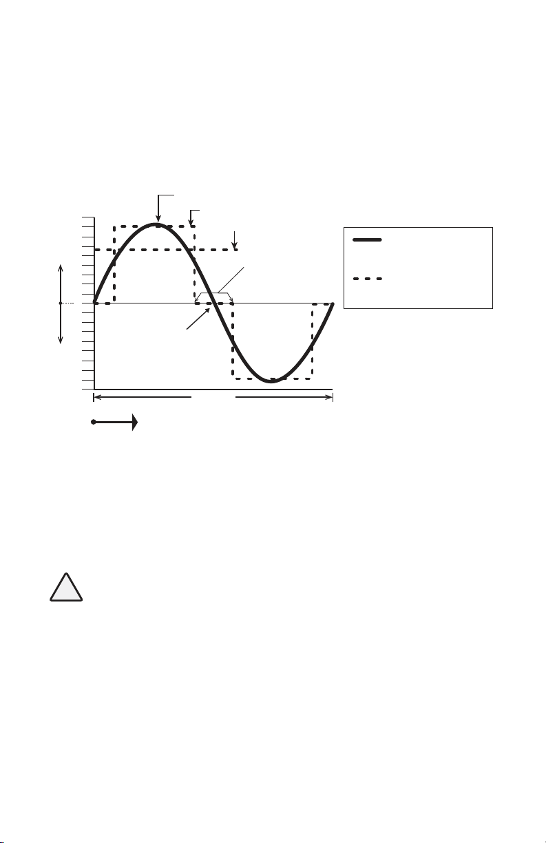
stages.Intherststage,the12VDCisconvertedtohighvoltageDC(around160VDC)usinghighfrequencyswitchingandPulseWidthModulation(PWM)technique.Inthe2ndstage,the160VhighvoltageDCisconvertedto115V,60HzModiedSineWaveAC.(NOTE: 115V is the RMS value of the Modied Sine Wave AC voltage. The peak
value of the Modied Sine Wave AC voltage will be equal to the value of the above
high voltage of around 160V. See the Fig 2.1).