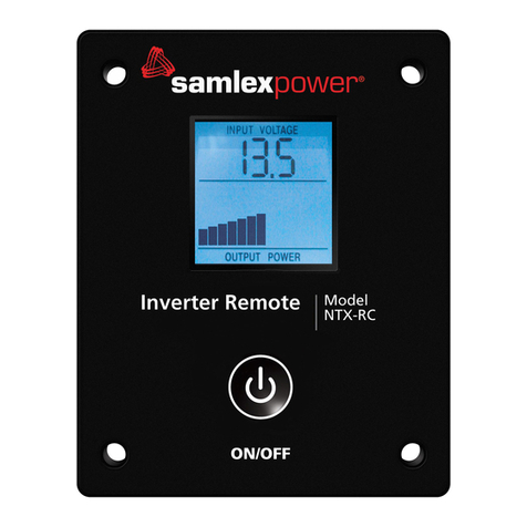
SamplexPower Evolution EVO-RC User manual

SECTION 1 | Introduction and Layout
The following safety symbols will be used in this manual to highlight safety and information:
!
CAUTION!
Indicates possibility of damage to the equipment in case of non-compliance.
i
INFO
Indicates useful supplemental information.
1.0 INTRODUCTION AND LAYOUT
The EVO-RC Remote Control allows you to monitor and customize the operating parameters of Samlex Evolution™
Series Inverter/Charger Models (i) 120 VAC Model Nos. EVO-2212 / EVO-3012 / EVO-2224 / EVO-4024 and
(ii) 230 VAC Model Nos. EVO-2212E / EVO-3012E / EVO-2224E / EVO-4024E.
It has its own internal Real Time Clock (RTC) and Super Capacitor type of battery for clock operation.
NOTE: This version of the manual has been adapted for use with (i)120 VAC Model Nos. EVO-2212 / EVO-3012 /
EVO-2224 / EVO-4024 and (ii) 230 VAC Model Nos. EVO-2212E / EVO-3012E / EVO-3012E / EVO-2224E / EVO-4024E.
1. LCD Screen - 2 rows of 16
characters each
2. ON/OFF Key
3. Green LED “Status”
4. Red LED “Fault"
5. Navigation Key “Back”
6. Navigation Key “Up”
7. Navigation Key “Down”
8. Navigation Key “Enter”
9. SD Card Slot - FAT16/32
format; Up to 32GB
10. RJ-45 Jack (At the back-not
shown). See pinout below:
Fig 1.1 Optional Remote Control EVO-RC - Layout & Dimensions
Pin # Signal
112V
212V
3ON/OFF
4D+
5D-
6NC
7GND
8GND
12345678 123 456
(View - Looking into the Jack)
1
2
78
6
3
5
9
4
Fault
132 mm
114 mm102 mm
144 mm

1.1 LAYOUT AND DIMENSIONS
1.2 CONNECTING CABLE
Connecting cable shown in Fig 1.2(a) has been provided
to connect the EVO-RC Remote Control to the EVOTM
Inverter/ Charger Models (i) 120 VAC Model Nos. EVO-
2212 / EVO-3012 / EVO-2224 / EVO-4024 and (ii) 230
VAC Model Nos. EVO-2212E / EVO-3012E / EVO-4024E.
Details of the connecting cable are as follows:
•Length of cable [1, Fig 1.2(a)] : 10m / 33ft
•No. of conductors: 8
•RJ-45 (8P8C) Plugs on either end [2, Fig 1.2(a)
•Pinouts and interconnection of the RJ-45 Plugs are
shown in Fig 1.2(b)
SECTION 1 | Introduction and Layout
1
22
Fig 1.2 (a) Connecting Cable
Straight
Connection
Top view of Plug -
Locking Tab facing down
Fig 1.2 (b) Pinout and Interconnection of RJ-45 Plugs
8P 8C, RJ-45 Modular Plug
RJ-45
Pin# Signal
112V
212V
3ON/OFF
4D+
5D-
6NC
7GND
8GND
Pin Out of
Plug - End 1
RJ-45
Pin# Signal
112V
212V
3ON/OFF
4D+
5D-
6NC
7GND
8GND
Pin Out of
Plug - End 2

2.1 INSTALLATION GUIDELINES
The remote control is provided with 10M/33ft, Connecting Cable (See Section 1.2). Check the proposed routing distance
of the wire and use longer wire, if necessary.
•Flush mounting of the Remote requires appropriate cut-out in the wall/panel (Dotted line in Fig 2.1) For this,
a paper template has been provided with the unit. Take necessary precautions to ensure any wiring/plumbing
running behind the wall/panel is not damaged.
•Route the wire to ensure there are no kinks.
•Use appropriate grommets when the wire is passed through holes in studs/partitions to prevent damage to
insulation.
2.1.2 TOOLS REQUIRED
Following tools are recommended:
• Phillips Head Screwdriver • Level • Hand Drill
• Knife/Saw • Pencil • Drill Bit (2.5mm / #39)
• Paper Template for cut-out (supplied with the unit)
102 mm / 4.02 in
122 mm / 4.80 in
132 mm / 5.18 in
Cut the wall / panel along the dotted
line with a jig saw.
This will create a pocket in the wall /
panel for ush mounting the EVO-RC.
Fig 2.1 EVO-RC Remote Cutout Dimensions for Wall/ Panel Mounting
2.2 FLUSH MOUNT INSTALLATION
To ush mount, the wall opening must have at least a 2” (5 cm) depth to make room for the remote and cable. Also,
the thickness of wall/panel board at the place of mounting should not be more than 13 mm to ensure that the RJ-45
jack opening is not obstructed (see Fig. 2.3).
11. Cut an opening in the wall using the supplied paper template (Based on Fig 2.1).
12. Drill four pilot holes (use 2.5mm diameter/#39 drill bit) for the 4 screws (3mm diameter, 16mm long) that will
attach the remote to wall (refer to Figure 2.1 for hole locations and dimensions).
13. Route one end of the cable through wall opening to the EVO™Inverter/Charger, and then plug it into the RJ-45
Remote Control Jack port on the EVO™Inverter/Charger.
SECTION 2 | Installation

SECTION 2 | Installation
14. Take the other end of remote cable and plug it into the RJ-45 Jack at the back of
the EVO-RC (Fig. 2.3).
15. Check the remote display to ensure the Power-up self test initiates.
16. If the self test is successful, secure the EVO-RC to the wall using the four screws (Fig 2.2)
Flush mounting the EVO-RC on the wall with 4pcs, Φ3mm self-tapping, at head screws
(supplied with the unit).
Fig 2.2 EVO-RC Flush Mounting
The thickness of the wall/panel board at the place of mounting should not be more than 15mm
to ensure that the RJ-45 jack opening is not obstructed.
Fig 2.3 Wall/Panel Thickness
3.0 GENERAL INFORMATION
EVO-RC Remote Control provides the user with the ability to modify EVO™Inverter/Charger’s operating
parameters. The default settings in EVO™Inverter/Charger are adequate for some installations but may have to be
modified for others. This Section provides details on the remote functions, status and menu maps and displays, fault
messages and parameter settings.
15mm
35.4mm
RJ-45 Jack
Bottom view
WALL/ PANEL BOARD

3.1 NAVIGATING THE REMOTE
The EVO-RC provides menu items and adjustable settings to congure your EVO™Inverter/Charger to your specic
parameters. Please refer to the layout at Fig 1.1.
•LCD Display (1) – The 2-line (16 characters each) LCD display with programmable backlight level shows status
and information for the EVO™Inverter/Charger. All Setup Menus and faults also appear on the LCD display.
The level of brightness / dimming of the LCD backlight can be programmed to suit user preference. (See Section
4.9 for details)
•ON/OFF Key (2) – The ON/OFF Key is used for switching ON/switching OFF the EVO™Inverter/Charger.
•Navigation Keys (5, 6, 7, 8) – These four Keys allow simple access to menu items that assists conguring,
monitoring, and troubleshooting the EVO™Inverter/Charger.
oNavigation Key Functions:
•Back – Return to previous selection
•Up – Scroll to higher Screen Nos. / Parameter Group Nos. in various Menu Maps
•Down – Scroll to lower Screen Nos. / Parameter Group Nos. in various Menu Maps
•Enter – Enter the selected option
• Status – Green LED indicator for indicating operating status (See details at Section 6, Table 6.1)
•Alarm (Fault) – Red LED indicator for indicating fault conditions (See details at Section 6, Table 6.1)
•SD Card socket – This slot supports SD memory card (up to 32GB; FAT 16/32). The SD Card is used for (i) Data
logging of EVO™Inverter/Charger's operational statistics and events and (ii) Saving and uploading of programmed
parameters (See Section 5: SD Card)
3.2 POWER ON / POWER OFF
i
INFO
a) Minimum battery voltage required for initiating manual switching ON of the unit is as follows:
•12V units ----- Higher than 9V
•24V units ---- Higher than 18V
b) Please note that this unit is designed to POWER ON AUTOMATICALLY if (i) AC voltage of 70V ± 5 VAC is
available at the AC Input Terminals and (ii) DC input voltage is > 12V for 12V versions of EVO™ and >24V
for 24V versions of EVO™. If the AC input voltage and frequency are within the programmed limits, the
unit will automatically operate in “Charging Mode”. If the AC input voltage and frequency are not within
the programmed limits, the unit will operate in “Inverting" Mode. Further, as long as AC input voltage >
70 ± 5 VAC is present, the unit CANNOT BE POWERED OFF using the ON / OFF Button on the front panel
of the unit or on the Remote Control EVO-RC. Switch OFF the AC input rst if the unit is required to be
powered off. However, if the unit is in “Fault Mode”, it will be possible to power OFF the unit with the
help of the ON/OFF Push Button on the front panel of the EVOTM unit (11, Fig 2.1 in the EVOTM Owner's
Manual) or, with the On/Off Key on the EVO-RC Remote Control (2, Fig 1.1)
c) Before proceeding, conrm that the unit is NOT in "Standby" Mode. If it is in "Standby Mode", the
"Status" LED (3, Fig 1.1) will ash once every 5 sec and the LED screen will display one of the "Standby
Mode" Screens show in Figs 3.2 (Column 2, GROUP 1). Press the On/Off Push Botton (2, Fig 1.1) on the
EVO-RC to exit the "Standby Mode" to the current operating mode. Refer to Section 3.4 for more details
on "Standby Mode".
SECTION 3 | Operation

SECTION 3 | Operation
3.2.1 Power ON - AC INPUT IS NOT PRESENT
The sequence given below in Fig 3.1(a) is applicable when there is no AC input and the unit is switched ON.
Press On/Off Key and hold for 2 second to turn the EVO™Inverter/Charger ON.
P OW E R O N . . .
Screen (a)
S E A R C H I N G I D . .
Screen (b)
E V O - X X X X V X . X X
I N V E R T E R / C H A R G E R
Screen (c)
I N V E R T I N G
O U T P U T 1 2 0 . 0 0 V
Screen (d)
Fig 3.1(a) Power On Sequence
(No AC Input)
When the EVO™ Inverter/Charger is OFF and the On/Off Key is pressed and
held, the LCD screen shows “POWER ON…" [Screen (a)]and the Status LED
ashes 3 times. On/Off Key may be released now. After 2 seconds, EVO-RC
starts to search for the communication ID of the EVO™ Inverter/Charger it is
attached to. The LCD screen shows “SEARCHING ID …” [Screen (b)]and the ID
number which is found is shown at the end of the line. When the default ID of
“1” is found, the display will then show the EVO™ Inverter/Charger Model No.
and rmware version (3 digit number X.XX) [Screen (c)]. The screen will then
change to the Inverting Mode Screen [Screen (d)].
3.2.2 Power OFF - AC INPUT IS NOT PRESENT
NOTE:
If the EVO™ Inverter/Charger has AC input voltage over 70 ± 5 VAC available at AC input terminals, the
Power OFF function is disabled and the unit will remain in the ON condition if the power off sequence is
attempted. The AC input must be removed before the unit can be powered OFF.
The sequence given below in Fig 3.1(b) is applicable when the unit is required to be powered off when no AC input is
present.
Press On/Off Key and hold for 5 seconds to turn OFF the EVO™ Inverter/Charger.
P OW E R O F F !
Fig 3.1(b) Power Off Sequence
(No AC Input)
When EVO™ Inverter/Charger is ON and the On/Off key is pressed and held for
minimum of 5 seconds, the LCD screen will show “POWER OFF !” and both the
Status and Alarm/ Fault LEDs will turn ON. Now release the On/Off key (please
note that Power Off sequence will be completed and display “POWER
OFF !” will disappear only when the On/Off key is released).

3.3 DATE AND TIME SETUP
Set date and time as per procedure given at Section 4.10: “Group 6 Parameter Setup: Time Setting”.
3.4 STANDBY MODE
When the EVO™ is in Standby Mode, inverting or charging / AC pass through will be suspended.
i
INFO
Standby Mode may be used to temporary halt normal operation of the Inverter/Charger without switching
OFF the unit completely.
For the Standby Mode to be switched ON, the EVO™ should be in ON condition and should be operating in one of the
4 Operating Modes – “Inverting” or “Charging”, “Power Saving” or "Online" (See Fig 3.2). When Standby Mode is
switched ON, the EVO™ will suspend its Operating Mode.
3.4.1 Procedure to Enter and Exit Standby Mode / Status Display in Standby Mode
i
INFO
• EVO-RC Remote Control is required to enter Standby Mode as explained in Section 3.4.1.1 below. Once
Standby Mode is entered, it can ALSO be switched off using the On/Off Push Button on the front panel of
the EVOTM Inverter/Charger Unit (See Section 3.4.1.2)
•If the EVO-RC Remote Control has NOT been connected to the EVOTM Inverter/Charger Unit, Standby Mode
cannot be entered using the On/Off Push Button on the front panel of the EVOTM Inverter/Charger Unit
3.4.1.1 Entering Standby Mode Using Remote Control EVO-RC: Changing over from any Operating
Mode (“Inverting”, “Charging” or “Power Save”) to Standby Mode can be carried out with the help of
Remote-Control EVO-RC as follows:
a) From any Operating Mode Screen (“Inverting”, “Charging” or “Power Save”), press the On/Off Push Key (2, Fig 1.1)
momentarily (0.1 sec)
b) Screen 1 below will be displayed rst for 1 sec followed by Screen 2 below for 1 sec. This display sequence will
be displayed 2 times and then, the screen will go back to the Operating Mode Screen.
•If Standby Mode is required to be activated, press the On/Off Push Key (2, Fig 1.1) momentarily (0.1 sec)
•If Standby Mode is not required to be activated, press the Back Key (5, Fig 1.1) momentarily (0.1 sec)
Screen 1: Screen 2:
G o t o S t a n d b y ?
Y e s = O n / O f f k e y
G o t o S t a n d b y ?
N o = B a c k k e y
c) On entering Standby Mode, the following will be displayed:
SECTION 3 | Operation

SECTION 3 | Operation
i. On the EVO-RC: The LCD will show the 1st screen
S T A N D B Y
B A T T E R Y 1 2 . 0 0 0 V
of the 7 Standby Mode Screens
(See Screens 1 to 7 of screens shown under Group 1, Standby Mode in Fig 3.2) and Status LED (3, Fig 1.1) will
blink once every 5 sec
ii. On the Front Panel of EVOTM Inverter/Charger: The Green LED marked “ON” (12, Fig 2.1 of the EVOTM
Owner's Manual) will blink once every 5 sec. Red LED marked “FAULT” (13, Fig 2.1 of the attached EVOTM
Owner's Manual) and Buzzer will be off
3.4.1.2 Exiting Standby Mode: Standby Mode can be exited as follows:
•Using EVO-RC: To exit Standby Mode using Remote Control EVO-RC, press the On/Off Key (2, Fig 1.1)
momentarily (0.1 sec).
•From Front Panel of EVOTM Inverter/Charger: It is NOT POSSIBLE to exit Standby Mode by momentary pressing of
the On/Off Push Button on the front panel of EVOTM (11, Fig 2.1 of the attached EVOTM Owner's Manual) if
EVO-RC Remote is NOT connected to EVO.
i
INFO
When Standby Mode is exited, the EVOTM Inverter/Charger Unit will execute the programmed Operating
Mode from the beginning. It will NOT start from the last condition of the operating stage it was in when
Standby Mode was activated.
3.5. FAULT MESSAGES & CLEARING FAULTS
If any fault occurs, the LCD screen will display the Fault Message and the Red LED “Fault” will be lighted. Refer to Table
7.1 in Section 7 for details of various fault messages and procedure to clear the fault.
!
CAUTION!
The cause of the fault must be removed before the unit is restarted.
!
ATTENTION!
La cause du défaut doit être éliminée avant le redémarrage de l'unité.
3.6 OPERATING MODES AND ASSOCIATED LCD DISPLAY SCREENS
3.6.1 Menu Maps for Operating Mode Screens
When the unit is operating normally, the LCD Screen will display the name of the Operating Mode and values of
various associated operating parameters. As all the operating parameters associated with a particular Operating Mode
cannot be displayed in one screen, multiple screens are available that can be accessed by scrolling the screens using the
Up and Down Keys. For ease of navigating through the various screens, all the screens covering a particular
Operating Mode have been arranged in the associated Menu Map. Table 3.1 shows the names of the Operating
Modes and the Fig Nos. of the associated Menu Maps.

Table 3.1 Operating Modes and Associated Menu Maps/ LCD Display Screens
Operating Mode Description Section and Fig No. of
Associated Menu Map
STANDBY MODE Standby Mode: No output, No AC bypass, No Charging Section 3.6.2
Fig 3.2
INVERTING MODE Unit is operating as an inverter Section 3.6.2
Fig 3.2
CHARGING MODE Unit is operating as a battery charger and passing through the AC input
to the loads
Section 3.6.2
Fig 3.2
POWER SAVING MODE Unit is in Power Saving Mode Section 3.6.2
Fig 3.2
ON LINE Unit is in On Line Mode Section 3.7
Fig 3.3(a) to 3.3(d)
CHARGER ONLY
Applicable when Parameter "ONLINE MODE", Option: 2=Charger is
selected. Provides charging and pass through when the AC input is
available. No inverting when the AC input is not available.
Section 3.8
Fig 3.4(a) & 3.4(b)
CHGR STOP
BY BMS
Applicable when Parameter "BATTERY TYPE", Option: 1=Lithium is selected.
This mode is activated when the Lithium Battery Management System
(BMS) sends command to EVO™ (contact closure signal) to stop charging to
prevent battery over voltage or over temperature.
Section 3.9
Fig 3.5
INV STOP
BY BMS
Applicable when Parameter "BATTERY TYPE ",Option : 1=Lithium is
selected. This mode is activated when the Lithium Battery Management
System (BMS) sends command to EVO™ (contact closure signal) to stop
inverting to prevent deep discharge of the battery.
Section 3.10,
Fig 3.6
3.6.2 Menu Map for Standby/ Inverting/ Charging/ Power Save Modes
Fig 3.2 shows Menu Map for the 4 main Operating Modes: (i) STANDBY MODE (ii) INVERTING MODE (iii) CHARGING
MODE and (iv) POWER SAVING MODE.
Any screen within Menu Map in Fig 3.2 for the 4 Main Operating Modes can be identied by 2 co-ordinates: Operating
Mode Group No (Column) and Display Screen No (Row).
Menu Maps/ Display Screens detailed in Table 3.2 are self-explanatory.
3.6.3 Charging Prole and Charging Stage information included in Charging Mode Display Screens
When the unit is operating in Charging Mode, all the relevant operating information related to this mode is displayed
through 19 scrollable screens (Screen Nos 1 to 19) as shown in Fig 3.2 under Column 4 - “GROUP 3: CHARGING
MODE”
The left corner of the 1st line of the display screen shows “CHARGING” and the right corner shows coded / abbreviated
information as follows:
a) The rst character of the right-hand corner display indicates the code for the Charging Prole that is active:
i. Numeral 0 to 5 for 6 options for 3-Stage / 2-Stage Charging Proles (Refer to Section 4.4.2.21 for details), or
ii. Letter “E” for 4-Stage Adaptive Prole for Equalization (Refer to Section 4.4.2.12)
b) The other portion of the right-hand corner display provides the following coded information pertaining to the
Charging Stage that is active:
SECTION 3 | Operation

SECTION 3 | Operation
•CC for Constant Current Stage
•CV for Constant Voltage 2nd Stage in 3-Stage / 2-Stage Charging Proles
•E-CVA for Constant Voltage Absorption Stage in 4-Stage Adaptive Charging Prole for Equalization
•E-CVE for Constant Voltage Equalization Stage in 4-Stage Adaptive Charging Prole for Equalization
•FLOAT for Float Stage
•OFF for charger off
Consolidated information related to the 1st line right hand corner display is given in Table 3.2 below:
TABLE 3.2 Codes / Abbreviation used in Charging Mode screens for Display of Charging Proles / Charging Stages
1st line, right corner
display under “GROUP
3: CHARGING MODE”
screens in Fig 3.2
Description
0-CC Constant Current, Bulk Stage, Parameter CHARGING PROFILE option : 0=3Stg Adaptiv
1-CC Constant Current, Bulk Stage, Parameter CHARGING PROFILE option : 1=3Stage Type1
2-CC Constant Current, Bulk Stage, Parameter CHARGING PROFILE option : 2=3Stage Type2
3-CC Constant Current, Bulk Stage, Parameter CHARGING PROFILE option : 3=2Stage Type1
4-CC Constant Current, Bulk Stage, Parameter CHARGING PROFILE option : 4=2Stage Type2
5-CC Constant Current, Bulk Stage, Parameter CHARGING PROFILE option : 5=2Stage Type3
E-CC Constant Current, Bulk stage of 4-Stage Adaptive Prole for Equalization
0-CV Constant Voltage, Absorption stage, Parameter CHARGING PROFILE option : 0=3Stg Adaptiv
1-CV Constant Voltage, Absorption Stage, Parameter CHARGING PROFILE option : 1=3Stage Type1
2-CV Constant Voltage, Absorption Stage, Parameter CHARGING PROFILE option : 2=3Stage Type2
3-CV Constant Voltage, Absorption Stage, Parameter CHARGING PROFILE option : 3=2Stage Type1
4-CV Constant Voltage, Absorption Stage, Parameter CHARGING PROFILE option : 4=2Stage Type2
5-CV Constant Voltage, Absorption Stage, Parameter CHARGING PROFILE option : 5=2Stage Type3
E-CVA Constant Voltage, Absorption Stage of 4-Stage Adaptive Prole for Equalization
E-CVE Constant Voltage, Equalization Stage of 4-Stage Adaptive Prole for Equalization
0-FLOAT Float Stage, Parameter CHARGING PROFILE option : 0=3Stg Adaptiv
1-FLOAT Float Stage, Parameter CHARGING PROFILE option : 1=3Stage Type1
2-FLOAT Float Stage, Parameter CHARGING PROFILE option : 2=3Stage Type2
3-OFF Charger Off, AC bypass, Parameter CHARGING PROFILE option : 3=2Stage Type1
5-OFF Charger Off, AC bypass, Parameter CHARGING PROFILE option : 5=2Stage Type3
CHGR STOP BY BMS Charging switches off when Pins 4 and 5 of Battery Temperature Sensor Jack (6 in Fig 2.1 of EVOTM Owner's
Manual) are shorted by control signal from Lithium Ion Battery Management System (BMS).
For example, in Fig 3.2, the 1st line of information under Column 4 (GROUP 3: CHARGING MODE) shows “0-CC” in the
right corner. This means that the unit is charging under the following conditions:
•CHARGING PROFILE: Option “0=3Stg Adaptiv” i.e. 3-Stage Adaptive Charging Prole (Refer to Section 5.7 of the
EVOTM Owner’s Manual)
•Charging Stage: “CC” i.e. Constant Current Bulk Stage

SECTION 3 | Operation
Fig 3.2 Menu Map For Overall
Operating Mode Display Screens
NOTE: See Table 7.1 for fault messages
DISPLAY
SCREEN NO.
GROUP 1:
STANDBY MODE
GROUP 2:
INVERTING MODE
GROUP 3:
CHARGING MODE
GROUP 4:
POWER SAVING MODE
1
S T A N D B Y
B A T T E R Y 1 2 . 0 0 0 V
I N V E R T I N G
O U T P U T 1 2 0 . 0 0 V
C H A R G I N G 0 - C C2
1 2 0 . 0 0 V
P OW E R S A V I N G
B A T T E R Y 1 2 . 0 0 0 V
òñòñòñòñ
2
S T A N D B Y
O U T P U T 0 . 0 0 V
I N V E R T I N G
O U T P U T 6 0 . 0 0 H z
C H A R G I N G 0 - C C2
G R I D 6 0 . 0 0 H z
P OW E R S A V I N G
B A T T E X T 0 . 0 A
òñòñòñòñ
3
S T A N D B Y
G R I D 0 . 0 0 V
I N V E R T I N G
O U T P U T 1 0 . 0 0 A
C H A R G I N G 0 - C C2
G E N 0 . 0 0 V
P OW E R S A V I N G
I D = 1 R C = X X X
òñòñòñòñ
4
S T A N D B Y
G E N 0 . 0 0 V
I N V E R T I N G
O U T P U T 1 2 0 0 W
C H A R G I N G 0 - C C2
G E N 0 . 0 0 H z
P OW E R S A V I N G
E V O - X X X X V X . X X
òñòñòñ
5
S T A N D B Y
Y Y Y Y / M M / D D H H : M M
I N V E R T I N G
O U T P U T 1 2 0 0 V A
C H A R G I N G 0 - C C2
I N P U T 2 0 . 0 0 A
òñòñòñ
6
S T A N D B Y
I D = 1 R C = X X X
I N V E R T I N G
O U T P U T P F = 1 . 0 0 0
C H A R G I N G 0 - C C2
I N P U T 2 4 0 0 W
òñòñòñ
7
S T A N D B Y
E V O - X X X X V X . X X
I N V E R T I N G
B A T T E R Y 1 2 . 0 0 0 V
C H A R G I N G 0 - C C2
I N P U T 2 4 0 0 V A
òñòñ
8
I N V E R T I N G
B A T T E R Y 1 4 0 . 0 A
C H A R G I N G 0 - C C2
I N P U T P F = 1 . 0 0 0
ò ñ ò ñ
9
I N V E R T I N G
B A T T E X T 0 . 0 A
C H A R G I N G 0 - C C2
O U T P U T 1 2 0 . 0 0 V
òñòñ
10
I N V E R T I N G
B A T T E R Y 2 5 . 0 C
C H A R G I N G 0 - C C2
O U T P U T 1 5 . 0 0 A
òñòñ
11
I N V E R T I N G
G R I D 0 . 0 0 V
C H A R G I N G 0 - C C2
O U T P U T 1 2 0 0 W
òñòñ
12
I N V E R T I N G
G R I D X X . X X H z
C H A R G I N G 0 - C C2
O U T P U T 1 2 0 0 V A
òñòñ
13
I N V E R T I N G
G E N 0 . 0 0 V
C H A R G I N G 0 - C C2
O U T P U T P F = 1 . 0 0 0
òñòñ
14
I N V E R T I N G
G E N X X . X X H z
C H A R G I N G 0 - C C2
B A T T E R Y 1 2 . 0 0 0 V
òñòñ
15
I N V E R T I N G
I D = 1 R C = X X X
C H A R G I N G 0 - C C2
B A T T E R Y 4 0 . 0 A
òñòñ
16
I N V E R T I N G
E V O - X X X X V X . X X
C H A R G I N G 0 - C C2
B A T T E X T 0 . 0 A
òñ
17
C H A R G I N G 0 - C C2
B A T T E R Y 2 5 . 0 C
òñ
18
C H A R G I N G 0 - C C2
I D = 1 R C = X X X1
òñ
19
C H A R G I N G 0 - C C2
E V O - X X X X 1V X . X X1
Fault Message
Fault Fault
LEGEND FOR FIG 3.2
UP
ò
KEY
Move downwards to
higher Display Screen No.
(See Note 3 under "NOTES
FOR FIG 3.2" on Page 14)
ñ
DOWN
KEY
Move upwards to lower
Display Screen No.
(See Note 3 under "NOTES
FOR FIG 3.2"on Page 14)
1,2
Refer to Notes 1 & 2 under
"NOTES FOR FIG 3.2 on
Page 14
Please Refer to "NOTES FOR FIG
3.2" on Page 14 for additional
information related to this FIG 3.2
Parameter values shown in the screens
are the default values for the 12V
versions i.e. EVO-2212/3012.
UP
KEY
UP
KEY
UP
KEY
UP
KEY
UP
KEY
UP
KEY
DOWN
KEY
DOWN
KEY
DOWN
KEY
DOWN
KEY
DOWN
KEY
DOWN
KEY
UP
KEY
UP
KEY
UP
KEY
DOWN
KEY
DOWN
KEY
DOWN
KEY
UP
KEY
UP
KEY
UP
KEY
UP
KEY
UP
KEY
UP
KEY
UP
KEY
UP
KEY
UP
KEY
UP
KEY
UP
KEY
UP
KEY
UP
KEY
UP
KEY
UP
KEY
DOWN
KEY
DOWN
KEY
DOWN
KEY
DOWN
KEY
DOWN
KEY
DOWN
KEY
DOWN
KEY
DOWN
KEY
DOWN
KEY
DOWN
KEY
DOWN
KEY
DOWN
KEY
DOWN
KEY
DOWN
KEY
DOWN
KEY
UP
KEY
UP
KEY
UP
KEY
UP
KEY
UP
KEY
UP
KEY
UP
KEY
UP
KEY
UP
KEY
UP
KEY
UP
KEY
UP
KEY
UP
KEY
UP
KEY
UP
KEY
DOWN
KEY
DOWN
KEY
DOWN
KEY
DOWN
KEY
DOWN
KEY
DOWN
KEY
DOWN
KEY
DOWN
KEY
DOWN
KEY
DOWN
KEY
DOWN
KEY
DOWN
KEY
DOWN
KEY
DOWN
KEY
DOWN
KEY
UP
KEY
UP
KEY
UP
KEY
DOWN
KEY
DOWN
KEY
DOWN
KEY

SECTION 3 | Operation
NOTES FOR FIG 3.2:
1. • The 3-digit No. XXX in “RC-XXX” indicates the Firmware Revision No. for the Remote Control EVO-RC
• The 4-digit No. XX.X in EVO-VX.XX denotes the Firmware Revision No. for the EVO™ Inverter/Charger
• The 4-digit No. XXXX in EVO-XXXX denotes the Model No. of Evolution™ Series Inverter/Charger
i.e. EVO-2212 / 2224 / 3012 / 4024
2. The display on the top right corner of the 19 Display Screens (Display Screen Nos. 1 to 19) under “CHARGING”
Mode (Column 4, Group 3) indicates the Charging Prole & the Charging Stage. Refer to Section 3.6.3 & Table
3.2 for details.
3. The following convention has been used to show up and down scrolling of the screens:
UP
ò
KEY Press Up Key to scroll to the next screen in the downward direction towards higher Screen Nos
ñ
DOWN
KEY Press Down Key to scroll to the previous screen in the upward direction towards lower Screen Nos
4. See Section 3.7 for information on Operating Mode Display Screens when the unit is in On-Line Mode
5. Parameter values shown in the screens are the default values for the 12V versions i.e. EVO-2212/3012.
3.7 MENU MAPS FOR ON-LINE MODE SCREENS
i
INFO
Please refer to the following for additional information on "On-Line Mode":
•Section 4.8.5.2 of the EVOTM Owner's Manual for a description and application of "On-Line Mode"
•Section 4.4.2.13.2 for selecting programming option "1=On-Line" for On-Line Mode under
programming Parameter "MODE"(Section 4.4.2.13)
On-Line Mode Screens will be similar to the Off-line Mode Screens shown in Fig 3.2 for Menu Map for Overall Operating
Mode Screens. Each On-Line Mode Screen will show “ONLINE” in the right corner of the rst line of the screen. Each
screen will alternate every 2 sec between Off-Line Mode Screen and On-Line Mode Screen. Examples of Screen 1 of
each of the 4 Operating Modes is shown in Figs 3.3(a) to 3.3(d) below:
S T A N D B Y
B A T T E R Y 1 2 . 0 0 0 V
S T A N D B Y O N L I N E
B A T T E R Y 1 2 . 0 0 0 V
I N V E R T I N G
O U T P U T 1 2 . 0 0 0 V
I N V E R T I N G O N L I N E
O U T P U T 1 2 . 0 0 0 V
The above 2 Display Screens alternate every 2 sec The above 2 Display Screens alternate every 2 sec
Fig 3.3 (a) Example of Display Screen No. 1 of
7 Display Screens in Menu Map for “GROUP 1:
STANDBY MODE” (See Column 2 of Fig 3.2)
Fig 3.3 (b) Example of Display Screen No. 1 of
16 Display Screens in Menu Map for “GROUP 2:
INVERTING MODE” (See Column 3 of Fig 3.2)

C H A R G I N G 0 . C C
1 2 0 . 0 0 V
C H A R G I N G O N L I N E
1 2 0 . 0 0 V
P OW E R S A V I N G
B A T T E R Y 1 2 . 0 0 0 V
P W R S A V E O N L I N E
B A T T E R Y 1 2 . 0 0 0 V
The above 2 Display Screens alternate every 2 sec The above 2 Display Screens alternate every 2 sec
Fig 3.3 (c) Example of Display Screen No. 1 of
19 Display Screens in Menu Map for “GROUP 3:
CHARGING MODE” (See Column 4 of Fig 3.2)
Fig 3.3 (d) Example of Display Screen No. 1 of
4 Display Screens in Menu Map for “GROUP 4:
POWER SAVE MODE” (See Column 5 of Fig 3.2)
3.8 MENU MAP FOR “CHARGER ONLY” MODE SCREENS
i
INFO
Refer to Section 4.4.2.13.3 regarding programming option “2=CHARGER ONLY” under programming
parameter “MODE” (Section 4.4.2.13)
3.8.1 When this option is selected, the EVOTM will remain in “Charging Mode” as long as qualied AC input voltage is
available. During the time AC input is available, 19 scrollable Operating Mode Screens for “CHARGING MODE” will be
available as per Menu Map shown in Fig 3.4(a) on page 16 (This Menu Map is also shown in the Menu Map in Fig 3.2
at Column 4 under heading “GROUP 3, CHARGING MODE”)
3.8.2 In case AC input voltage fails or is switched off, EVOTM will NOT change over to “Inverting Mode” but will enter
“STANDBY MODE” (NOTE: AC side loads will lose AC power). During the time AC input is NOT available, 7 scrollable
Operating Mode Screens for STANDBY MODE will be displayed as shown in Menu Map at Fig 3.4(b) on page 16.
(Also shown in Menu Map at Fig 3.2 in Column 2 under heading “GROUP 1, STANDBY MODE”)
3.8.2.1 If attempt is made to exit “STANDBY MODE” by momentarily pressing the On/Off Key, message
C H A R G E R O N L Y
I N V E R T E R O F F
will be seen for some time and the screen will revert back to the “STANDBY
MODE” Screen that was being displayed
SECTION 3 | Operation

SECTION 3 | Operation
Fig 3.4 (a) Menu Map of Operating Mode Screens
in Charger Only Mode (AC input is available)
Fig 3.4 (b) Menu Map of Operating Mode Screens
in Charger Only Mode (No AC input)
DISPLAY
SCREEN NO.
DISPLAY SCREENS IN
CHARGER ONLY MODE
(NO AC INPUT)
1
S T A N D B Y
B A T T E R Y 1 2 . 0 0 0 V
òñ
2
S T A N D B Y
O U T P U T 0 . 0 0 V
òñ
3
S T A N D B Y
G R I D 0 . 0 0 V
òñ
4
S T A N D B Y
G E N 0 . 0 0 V
òñ
5
S T A N D B Y
Y Y Y Y / M M / D D H H : M M
òñ
6
S T A N D B Y
I D = 1 R C = X X X1
òñ
7
S T A N D B Y
E V O - X X X X 1V X . X X1
DISPLAY
SCREEN NO.
DISPLAY SCREEN
1
C H A R G I N G 0 - C C2
1 2 0 . 0 0 V
òñ
2
C H A R G I N G 0 - C C2
G R I D 6 0 . 0 0 H z
òñ
3
C H A R G I N G 0 - C C2
G E N 0 . 0 0 V
òñ
4
C H A R G I N G 0 - C C2
G E N 0 . 0 0 H z
òñ
5
C H A R G I N G 0 - C C2
I N P U T 2 0 . 0 0 A
òñ
6
C H A R G I N G 0 - C C2
I N P U T 2 4 0 0 W
òñ
7
C H A R G I N G 0 - C C2
I N P U T 2 4 0 0 V A
òñ
8
C H A R G I N G 0 - C C2
I N P U T P F = 1 . 0 0 0
òñ
9
C H A R G I N G 0 - C C2
O U T P U T 1 2 0 . 0 0 V
òñ
10
C H A R G I N G 0 - C C2
O U T P U T 1 5 . 0 0 A
òñ
11
C H A R G I N G 0 - C C2
O U T P U T 1 2 0 0 W
òñ
12
C H A R G I N G 0 - C C2
O U T P U T 1 2 0 0 V A
òñ
13
C H A R G I N G 0 - C C2
O U T P U T P F = 1 . 0 0 0
òñ
14
C H A R G I N G 0 - C C2
B A T T E R Y 1 2 . 0 0 0 V
òñ
15
C H A R G I N G 0 - C C2
B A T T E R Y 4 0 . 0 A
òñ
16
C H A R G I N G 0 - C C2
B A T T E X T 0 . 0 A
òñ
17
C H A R G I N G 0 - C C2
B A T T E R Y 2 5 . 0 C
òñ
18
C H A R G I N G 0 - C C2
I D = 1 R C = X X X1
òñ
19
C H A R G I N G 0 - C C2
E V O - X X X X 1V X . X X1
UP
KEY
UP
KEY
UP
KEY
UP
KEY
UP
KEY
UP
KEY
DOWN
KEY
DOWN
KEY
DOWN
KEY
DOWN
KEY
DOWN
KEY
DOWN
KEY
UP
KEY
UP
KEY
UP
KEY
UP
KEY
UP
KEY
UP
KEY
UP
KEY
UP
KEY
UP
KEY
UP
KEY
UP
KEY
UP
KEY
UP
KEY
UP
KEY
UP
KEY
DOWN
KEY
DOWN
KEY
DOWN
KEY
DOWN
KEY
DOWN
KEY
DOWN
KEY
DOWN
KEY
DOWN
KEY
DOWN
KEY
DOWN
KEY
DOWN
KEY
DOWN
KEY
DOWN
KEY
DOWN
KEY
DOWN
KEY
UP
KEY
UP
KEY
UP
KEY
DOWN
KEY
DOWN
KEY
DOWN
KEY
LEGEND FOR FIGS 3.4(a) and 3.4(b):
1. • The 3-digit No. XXX in “RC-XXX” indicates the Firmware Revision No. for the Remote
Control EVO-RC
• The 4-digit No. XX.X in EVO-VX.XX denotes the Firmware Revision No. for the EVO™
Inverter/Charger
• The 4-digit No. XXXX in EVO-XXXX denotes the Model No. of Evolution™ Series
Inverter/Charger
i.e. EVO-2212 / 2224 / 3012 / 4024
2. The display on the top right corner of the 19 Display Screens (Display Screen Nos. 1 to
19) in Fig 3.4(a) indicates the Charging Prole & the Charging Stage. Refer to Section
3.6.3 & Table 3.2 for details.
3. The following convention has been used to show up and down scrolling of the screens:
UP
ò
KEY
Press Up Key to scroll to the next screen in the downward direction
towards higher Screen Nos
ñ
DOWN
KEY
Press Down Key to scroll to the previous screen in the upward direction
towards lower Screen Nos
4. Parameter values shown in the screens are the default values for the 12V versions
i.e. EVO-2212/3012.

SECTION 3 | Operation
DISPLAY
SCREEN NO.
DISPLAY SCREEN
1
C H G R S T O P B Y B M S
1 2 0 . 0 0 V
òñ
2
C H G R S T O P B Y B M S
G R I D 6 0 . 0 0 H z
òñ
3
C H G R S T O P B Y B M S
G E N 0 . 0 0 V
òñ
4
C H G R S T O P B Y B M S
G E N 0 . 0 0 H z
òñ
5
C H G R S T O P B Y B M S
I N P U T 2 0 . 0 0 A
òñ
6
C H G R S T O P B Y B M S
I N P U T 2 4 0 0 W
òñ
7
C H G R S T O P B Y B M S
I N P U T 2 4 0 0 V A
òñ
8
C H G R S T O P B Y B M S
I N P U T P F = 1 . 0 0 0
òñ
9
C H G R S T O P B Y B M S
O U T P U T 1 2 0 . 0 0 V
òñ
10
C H G R S T O P B Y B M S
O U T P U T 1 5 . 0 0 A
òñ
11
C H G R S T O P B Y B M S
O U T P U T 1 2 0 0 W
òñ
12
C H G R S T O P B Y B M S
O U T P U T 1 2 0 0 V A
òñ
13
C H G R S T O P B Y B M S
O U T P U T P F = 1 . 0 0 0
òñ
14
C H G R S T O P B Y B M S
B A T T E R Y 1 2 . 0 0 0 V
òñ
15
C H G R S T O P B Y B M S
B A T T E R Y 4 0 . 0 A
òñ
16
C H G R S T O P B Y B M S
B A T T E X T 0 . 0 A
òñ
17
C H G R S T O P B Y B M S
B A T T E R Y 2 5 . 0 C
òñ
18
C H G R S T O P B Y B M S
I D = 1 R C = X X X1
òñ
19
C H G R S T O P B Y B M S
E V O - X X X X 1V X . X X1
3.9 MENU MAP FOR “CHARGER STOP BY BMS”
MODE SCREENS
i
INFO
For background information, refer to Section
4.4.2.22.2 regarding “Stop Charging” control by
Lithium Ion Battery Management System (BMS)
for on/off control of charging operation of EVOTM
Inverter/Charger.
When BMS activates “Stop Charging” signal (The
Drain-Source terminals of the BMS will close and
short Pins 1/2/3/4 and 5/6/7/8 of RJ-45 Jack marked
“Battery Temp Sensor” on the front panel of EVOTM),
EVOTM will stop charging (Internally, EVOTM will be
in Charging Mode, but the charging current will
be reduced to 0A). 19 scrollable display screens will
be available to show the status of various parameters
as shown in the Menu Map at Fig 3.5 on the left.
NOTE: The 19 “CHGR STOP BY BMS” display screens
shown in Fig 3.5 on the left are the same as the 19
display screens shown for Menu Map for screens for
“Charging Mode” (Fig 3.2 – Column 3 under heading
“GROUP 3: CHARGING MODE”) but with the 1st
line replaced with “CHGR STOP BY BMS”
LEGEND FOR FIG 3.5
UP
ò
KEY
Press Up Key to scroll the screen in the
downward direction towards higher
Screen Nos
ñ
DOWN
KEY
Press Down Key to scroll the screen in
the upward direction towards lower
Screen Nos
NOTE: Parameter values shown in the various
display screens are the default values for
12V versions i.e. EVO-2212 / EVO-3012
Fig 3.5 Menu Map for Display Screens during
"Charger Stop by BMS"
UP
KEY
UP
KEY
UP
KEY
UP
KEY
UP
KEY
UP
KEY
UP
KEY
UP
KEY
UP
KEY
UP
KEY
UP
KEY
UP
KEY
UP
KEY
UP
KEY
UP
KEY
DOWN
KEY
DOWN
KEY
DOWN
KEY
DOWN
KEY
DOWN
KEY
DOWN
KEY
DOWN
KEY
DOWN
KEY
DOWN
KEY
DOWN
KEY
DOWN
KEY
DOWN
KEY
DOWN
KEY
DOWN
KEY
DOWN
KEY
UP
KEY
UP
KEY
UP
KEY
DOWN
KEY
DOWN
KEY
DOWN
KEY

SECTION 3 | Operation
Fig 3.6 Menu Map for Display Screens during
"Charger Stop by BMS" Mode
DISPLAY
SCREEN NO.
DISPLAY SCREENS IN
CHARGER ONLY MODE
(NO AC INPUT)
1
I N V S T O P B Y B M S
B A T T E R Y 1 2 . 0 0 0 V
òñ
2
I N V S T O P B Y B M S
B A T T E R Y 0 . 0 0 V
òñ
3
I N V S T O P B Y B M S
G R I D 0 . 0 0 V
òñ
4
I N V S T O P B Y B M S
G E N 0 . 0 0 V
òñ
5
I N V S T O P B Y B M S
Y Y Y Y / M M / D D H H : M M
òñ
6
I N V S T O P B Y B M S
I D = 1 R C = X X X1
òñ
7
I N V S T O P B Y B M S
E V O - X X X X 1V X . X X1
3.10 MENU MAP FOR “INVERTER STOP BY BMS”
MODE SCREENS
i
INFO
For background information, refer to Section
4.4.2.22.2 regarding “Stop Inverting” control by
Lithium Ion Battery Management System (BMS)
for on/off control of inverting operation of EVOTM
Inverter/Charger
When BMS activates “Stop Inverting” signal
(The Drain-Source terminals of the BMS will close
and short Pins 1/2/3/4 and 5/6/7/8 of RJ-45 Jack
marked “Battery Temp Sensor” on the front panel
of EVO), EVOTM will stop inverting (Internally,
EVOTM will be in Standby Mode). 7 scrollable
display screens will be available to show the
status of various operating parameters as shown
in the Menu Map at Fig 3.6 on the right:
NOTE: The 7 “INV STOP BY BMS” display screens
shown in Fig 3.6 on the right are the same as
the 7 display screens shown for Menu Map for
“Standby Mode” (Fig 3.2 – Column 2 under
heading “GROUP 1: STANDBY MODE”) but with
the 1st line replaced with “INV STOP BY BMS”
LEGEND FOR FIG 3.6
UP
ò
KEY
Press Up Key to scroll the screen in the
downward direction towards higher
Screen Nos
ñ
DOWN
KEY
Press Down Key to scroll the screen in
the upward direction towards lower
Screen Nos
UP
KEY
UP
KEY
UP
KEY
UP
KEY
UP
KEY
UP
KEY
DOWN
KEY
DOWN
KEY
DOWN
KEY
DOWN
KEY
DOWN
KEY
DOWN
KEY

4.1 PARAMETER SETUP MENU MAPS
4.1.1 General Information
Up to 63 operating parameters (Figs 4.1 and 4.2) can be programmed to suit the desired operating conditions.
The 63 programming parameters have been arranged under 7 "PARAMETER GROUPS" (Displayed under heading"SELECT
GROUP") as shown in Parameter Setup Menu Map for "PARAMETER GROUPS" 1 - 4 in Fig 4.1 & for "PARAMETER
GROUPS" 5 - 7 in Fig 4.2.
i
INFO
Parameter Setup Menu Maps in Figs 4.1 & 4.2 have been explained using LCD screen displays with information
as seen on the actual LCD screens.
•All values shown in the second row of setup screen displays are the default parameters for EVO-2212/
3012/2212E/3012E.
•All voltage values related to battery voltages are the default values for 12V versions i.e. EVO-2212/3012/
2212E/3012E.
SECTION 4 | Parameter Setup

SECTION 4 | Parameter Setup
PARAMETER GROUP NO.1 PARAMETER GROUP NO.2 PARAMETER GROUP NO.3 PARAMETER GROUP NO.4
PARAMETER
SETUP SCREEN
NO.
S E L E C T G R O U P
C H A R G E C U R V E
ENTER KEY ò
UP KEY
ð
ï
DOWN KEY
S E L E C T G R O U P
I N P U T S E T T I N G
ENTER KEY ò
UP KEY
ð
ï
DOWN KEY
S E L E C T G R O U P
I N P U T L OW L I M I T
ENTER KEY ò
UP KEY
ð
ï
DOWN KEY
S E L E C T G R O U P
I N P U T H I G H L I M I T
ENTER KEY ò
UP KEY
ð
ï
DOWN KEY
1
B U L K C U R R E N T
4 0 A
UP KEY ò ñ DOWN KEY
D E F A U L T F R E Q
0 = 6 0 H z
UP KEY ò ñ DOWN KEY
R E S E T V O L T A G E
1 0 5 . 0 V
UP KEY ò ñ DOWN KEY
R E S E T V O L T A G E
1 2 5 . 0 V
UP KEY ò ñ DOWN KEY
2
A B S O R P V O L T A G E
1 4 . 4 0 V
UP KEY ò ñ DOWN KEY
G R I D M A X C U R R E N T
3 0 . 0 0 A
UP KEY ò ñ DOWN KEY
C U T O F F V O L T 1
1 0 0 . 0 V
UP KEY ò ñ DOWN KEY
C U T O F F V O L T 1
1 3 5 . 0 V
UP KEY ò ñ DOWN KEY
3
E Q U A L I Z E V O L T A G E
1 4 . 4 0 V
UP KEY ò ñ DOWN KEY
G E N M A X C U R R E N T
3 0 . 0 0 A
UP KEY ò ñ DOWN KEY
D E T E C T T I M E 1
3 0 0 c y c l e
UP KEY ò ñ DOWN KEY
D E T E C T T I M E 1
6 0 c y c l e
UP KEY ò ñ DOWN KEY
4
F L O A T I N G V O L T A G E
1 3 . 5 V
UP KEY ò ñ DOWN KEY
H I G H C U T O F F
6 5 . 0 0 H z
UP KEY ò ñ DOWN KEY
C U T O F F V O L T 2
9 5 . 0 V
UP KEY ò ñ DOWN KEY
C U T O F F V O L T 2
1 4 0 . 0 V
UP KEY ò ñ DOWN KEY
5
C OM P E N S A T E
4 m V / C / C e l l
UP KEY ò ñ DOWN KEY
H I G H R E S E T
6 4 . 0 0 H z
UP KEY ò ñ DOWN KEY
D E T E C T T I M E 2
6 0 c y c l e
UP KEY ò ñ DOWN KEY
D E T E C T T I M E 2
1 5 c y c l e
UP KEY ò ñ DOWN KEY
6
B A T T O V E R V O L T
1 6 . 0 0 V
UP KEY ò ñ DOWN KEY
L O W C U T O F F
5 5 . 0 0 H z
UP KEY ò ñ DOWN KEY
C U T O F F V O L T 3
9 0 . 0 V
UP KEY ò ñ DOWN KEY
C U T O F F V O L T 3
1 4 5 . 0 V
UP KEY ò ñ DOWN KEY
7
R E S E T V O L T A G E
1 4 . 0 0 V
UP KEY ò ñ DOWN KEY
L OW R E S E T
5 6 . 0 0 H z
UP KEY ò ñ DOWN KEY
D E T E C T T I M E 3
1 c y c l e
D E T E C T T I M E 3
1 c y c l e
8
L O W V O L T A L A R M
1 1 . 0 0 V
UP KEY ò ñ DOWN KEY
S Y N C G R I D
0 = F i n e
UP KEY ò ñ DOWN KEY
9
B A T T L OW V O L T A G E
1 0 . 5 0 V
UP KEY ò ñ DOWN KEY
S Y N C G E N
1 = C o a r s e
UP KEY ò ñ DOWN KEY
10
L V D E T E C T T I M E
10 sec
UP KEY ò ñ DOWN KEY
I N P U T O C P R O T E C T
0 = I N V m o d e
UP KEY ò ñ DOWN KEY
11
L V C U T O F F T I M E
1200 sec
UP KEY ò ñ DOWN KEY
I N P U T R E C O V E R Y
0 = B u f f e r e d
12
E Q U A L I Z E - 4 S T A G E S
0 = N o
UP KEY ò ñ DOWN KEY
13
M O D E
0 = N o r m a l
UP KEY ò ñ DOWN KEY
14
O N L I N E O P T I O N
0 = O p t i o n 1
UP KEY ò ñ DOWN KEY
15
R E S E T T O B U L K
1 2 . 0 0 V
UP KEY ò ñ DOWN KEY
16
G S D E T E C T T I M E
10 sec
UP KEY ò ñ DOWN KEY
17
G E N O N T I M E
6 0 m i n
UP KEY ò ñ DOWN KEY
18
G E N O F F D E L A Y
6 0 m i n
UP KEY ò ñ DOWN KEY
19
A B S O R P T I M E
6 0 m i n
UP KEY ò ñ DOWN KEY
20
A B S O R P E X I T A M P S
4 A
UP KEY ò ñ DOWN KEY
21
C H A R G I N G P R O F I L E
0 = 3 S t a g e T y p e 0
UP KEY ò ñ DOWN KEY
22
B A T T E R Y T Y P E
0 = L e a d A c i d
UP KEY ò ñ DOWN KEY
23
S A F E C H A R G I N G
1 m i n
UP KEY ò ñ DOWN KEY
24
E X T . C H A R G E R
0 = N o t a f f e c t
Fig 4.1 Parameter Setup Menu Map for Parameter Group Nos. 1 to 4
LEGEND & INFORMATION FOR FIG 4.1
Refer to Section 4.1.2 for detailed notes on navigating through this menu map
UP
ò
KEY
Press Up Key to scroll to next higher numbered Parameter Setup
screen
ñ
DOWN
KEY
Press Down Key to scroll to previous lower numbered Parameter
Setup screen
¦
*
Continue to Fig 4.2 on page 21 for Parameter Setup Menu Map
for Parameter Group Nos. 5 - 8
Parameter Values shown in the Parameter Setup Screens are the default values
for 12V versions i.e. EVO-2212/3012/2212E/3012E.
¦
*

SECTION 4 | Parameter Setup
PARAMETER GROUP NO.5 PARAMETER GROUP NO.6 PARAMETER GROUP NO.7 PARAMETER GROUP NO.8
PARAMETER
SETUP SCREEN
NO.
S E L E C T G R O U P
O T H E R F U N C T I O N
ENTER KEY ò
UP KEY
ð
ï
DOWN KEY
S E L E C T G R O U P
R C S E T T I N G
ENTER KEY ò
UP KEY
ð
ï
DOWN KEY
S E L E C T G R O U P
T I M E S E T T I N G
ENTER KEY ò
UP KEY
ð
ï
DOWN
KEY
S E L E C T G R O U P
S T O P S D C A R D
ENTER KEY ò
1
P OW E R S A V I N G
0 = D i s a b l e
UP KEY ò ñ DOWN KEY
A C T I V E L C D L I G H T
4 = 1 0 0 %
UP KEY ò ñ DOWN KEY
T I M E S E T T I N G
Y Y Y Y / M M / D D H H . M M
S T O P S D C A R D
0 = N o
2
E N T E R P O I N T
6 W
UP KEY ò ñ DOWN KEY
I D L E L C D L I G H T
1 = 2 5 %
UP KEY ò ñ DOWN KEY
3
W A K E U P P O I N T
7 W
UP KEY ò ñ DOWN KEY
I D L E L C D T I M E R
1 m i n
4
R E M O T E S W I T C H
0 = B u t t o n
UP KEY ò ñ DOWN KEY
5
R E L A Y F U N C T I O N
2 = G e n e r a t o r 0
UP KEY ò ñ DOWN KEY
6
C O M M . I D
1
UP KEY ò ñ DOWN KEY
7
B U Z Z E R
1 = O n
UP KEY ò ñ DOWN KEY
8
D I S C H A R G E B E E P
0 = O f f
UP KEY ò ñ DOWN KEY
9
D E F A U L T R E S E T
0 = N o
UP KEY ò ñ DOWN KEY
10
D A T A L O G T I M E
1 = 1 s e c
UP KEY ò ñ DOWN KEY
11
P A R A M E T E R S A V E
0 = N o
UP KEY ò ñ DOWN KEY
12
T E M P U N I T
0 = C
UP KEY ò ñ DOWN KEY
13
P A S S W O R D D I S A B L E
1 = Y e s
Fig 4.2 Parameter Setup Menu Map for Parameter Group Nos. 5 to 8
LEGEND & INFORMATION FOR FIG 4.2
Refer to Section 4.1.2 for detailed notes on navigating through this menu map
UP
ò
KEY
Press Up Key to scroll to next higher numbered Parameter Setup
screen
ñ
DOWN
KEY
Press Down Key to scroll to previous lower numbered Parameter
Setup screen
¦
*
Continued from Fig 4.1 on page 20 for Parameter Setup Menu
Map for Parameter Group Nos. 1 - 4
Parameter Values shown in the Parameter Setup Screens are the default values
for 12V versions i.e. EVO-2212/3012/2212E/3012E.
¦
*
This manual suits for next models
9
Other SamplexPower Remote Control manuals

SamplexPower
SamplexPower EVO-RC User manual

SamplexPower
SamplexPower SSW-R1-12B User manual

SamplexPower
SamplexPower SAM-RC User manual

SamplexPower
SamplexPower NTX-RC User manual

SamplexPower
SamplexPower RC-300 User manual

SamplexPower
SamplexPower RC-15A User manual

SamplexPower
SamplexPower EVO-RC-PLUS User manual