V
19
AD CONVERTER
• Sams elektronik d.o.o. • 48 Zivka Davidovica st. • 11050 Belgrade • Serbia •
TECHNICAL SPECIFICATIONS
GENERAL INFORMATION
- Code: ....................................................................005.209
- Weight: ................................................................... 0.4 Kg
- Type: .....................................................................module
- Dimensions: ..................................................100 x 160mm
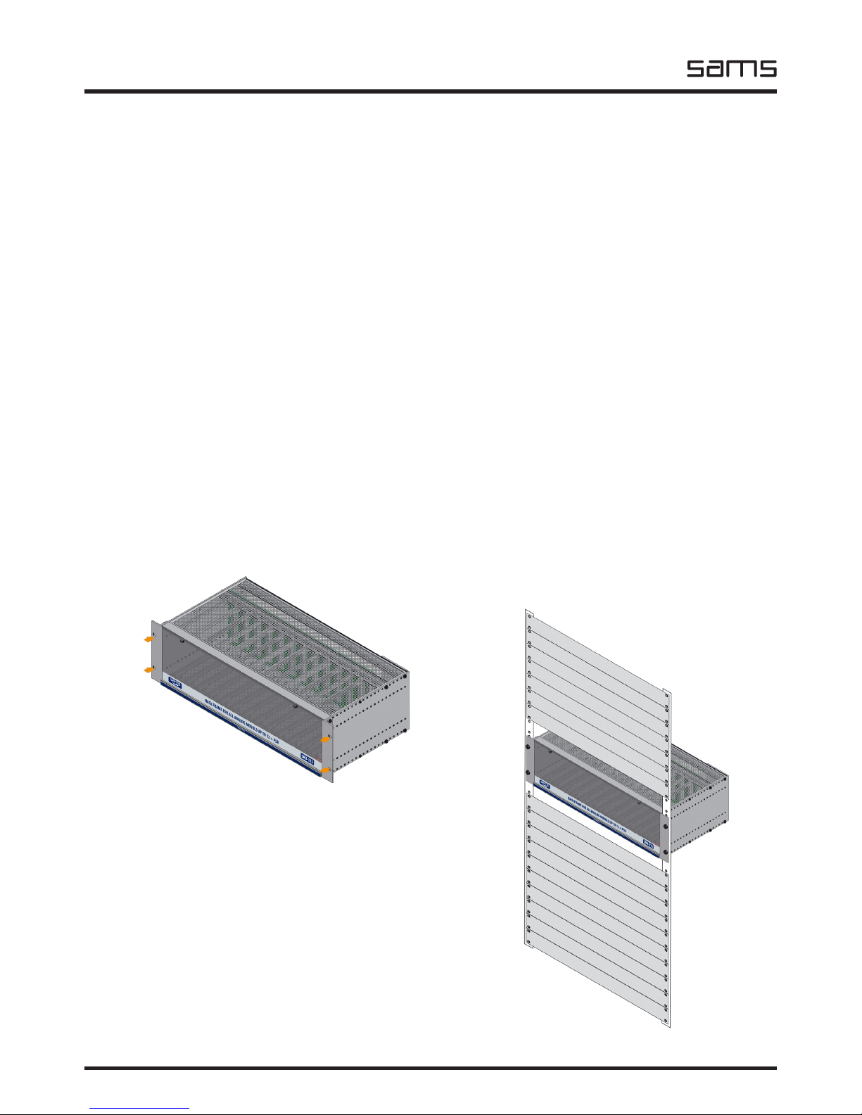
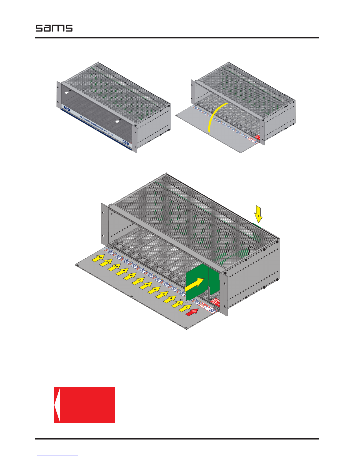
- Required: ..................... SRU rack frame, back panel ADCV-8
- Delivery includes: ................................. device, user manual
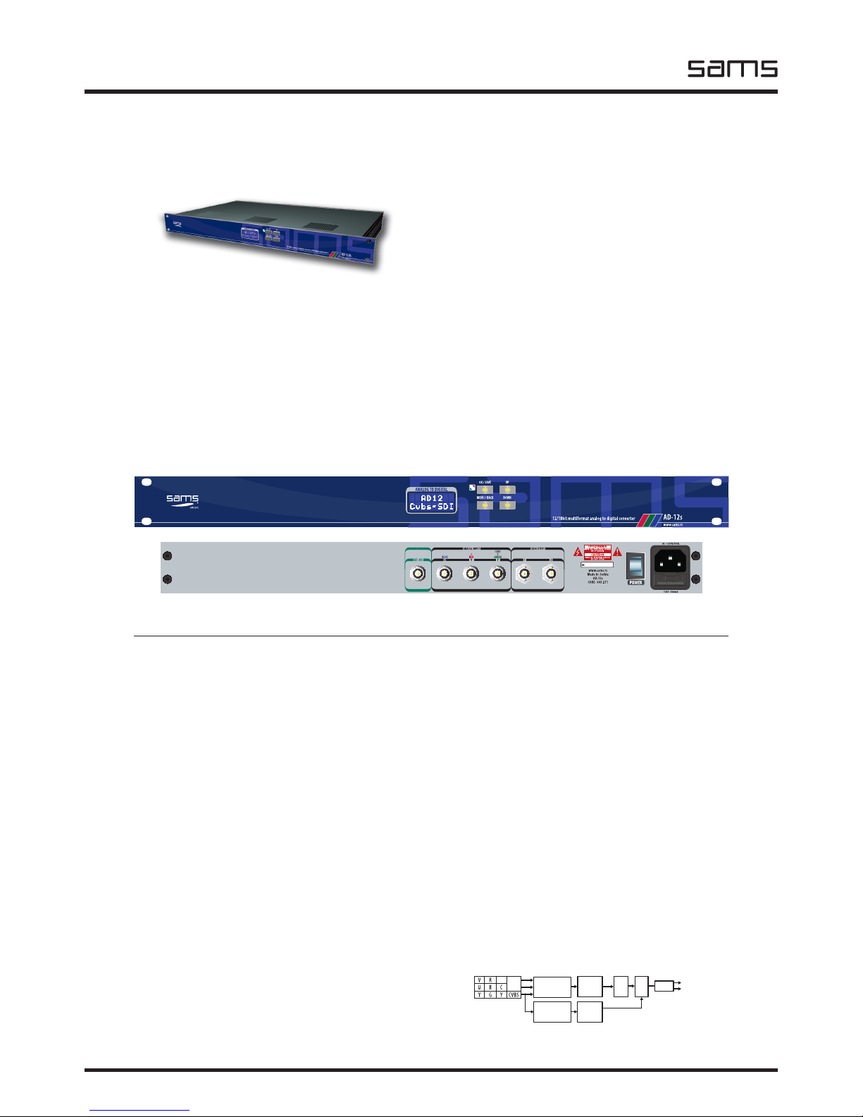
ANALOG INPUT
- Number: ..................... 3, (YUV, RGB, YC, CVBS) BNC female
- Impedance: .................................................................75Ω
DIGITAL OUTPUT
- Number: .......................................................2, BNC female
- Signal type: ............................... Serial digital (SMPTE259M)
- Impedance: .................................................................75Ω
- Jitter: ..< 0.2UI (Tipical 0.1UI @ Color Bar, 10Hz lter mode)
- Level: .......................................................... 800mV ± 10%
OUTPUT PERFORMANCE
- Bit resolution: .......................................10/12bit processing
- Black offset: ..................................................Self adjusting
- H adjustment range: ........................... 0-64μs in 37ηs steps
- V adjustment range: ......................... 0-5 lines in 1 line step
BLOCK DIAGRAM
ORDERING INFORMATION
Code Name Description
005.209 AD-12 ADC
001.509 ADCV-8 Back connector
001.605 SRU-306 Rack frame for 6 modules
BACK CONNECTOR ADCV-8
Specications and designs are subject to change without notice
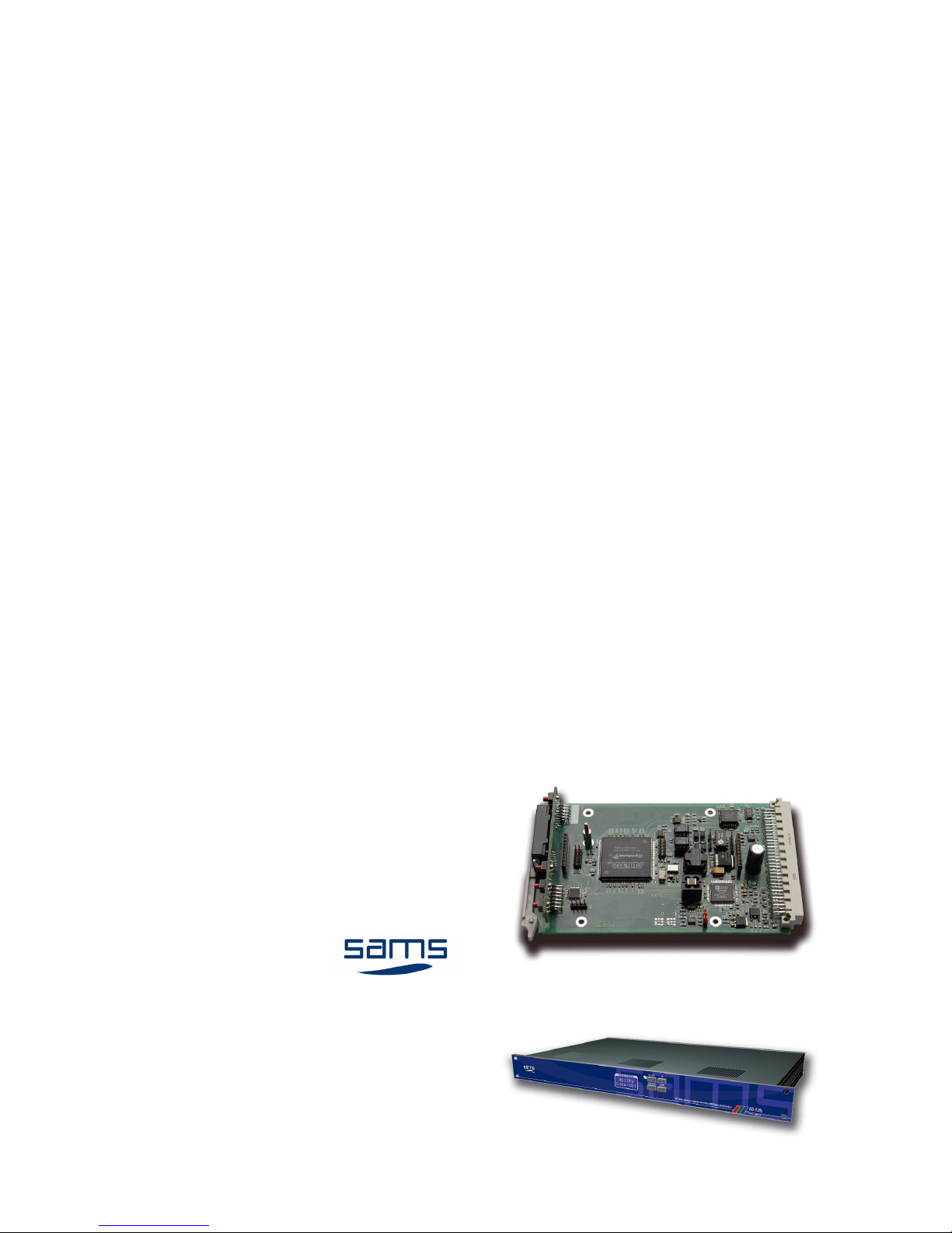
AD-12
Analog to SDI converter
- Broadcast quality
- Converts YUV, RGB, CVBS or YC to digital video
- 12/10bit processing
- Fiveline adaptive 3D comb lter
- Processing delay - 1line
- Integrated Three 54MHz: Noise Shaped Video, 12-bit AD
converter and 4 x oversampling
- Integrated automatic gain control with adaptive peak white
mode
- CTI (chroma transient improvement)
- DNR (Digital Noise Reduction)
- EDH processing
- Automatic YUV pixel timing adjustment
- Input signal presence detection
- Pass or broadcast test in the case of incorrect video input
- Integrated Test Generator (Black, Color Bar)
- Easy setup with local control and LCD display
POWER
- Voltage: ........................................................... 2 x 12V AC
- Power: .........................................................................5W
TEMPERATURE
- Performance: .......................................................... 5-40°C
- Operating: .............................................................. 0-50°C
AD-12 converts composite or component analog video to SDI. With both available, composite and component (Y, Cr, Cb or RGB
or YC) inputs, this unit is ideal for converting all types of analog video. Advanced and highly exible digital output, enables high-
quality conversion. “12bit 4x oversampling allows the A / D conversion of high-performance 10bit output. An intelligent adjustment
system provides full digital lter frequency response, even in the composite signal. Fixed frequency 54MHz ADC and buses for all
options, allows for very precise processing and digital ltering. The module is placed in the SRU-306 3RU chassis with capacity of
6 modules. Also, the device is available in standalone version.