V
30
DA CONVERTER
• Sams elektronik d.o.o. • 48 Zivka Davidovica st. • 11050 Belgrade • Serbia •
TECHNICAL SPECIFICATIONS
GENERAL INFORMATION
- Code: ....................................................................005.130
- Weight: ................................................................... 0.4 Kg
- Type: .....................................................................module
- Dimensions: ..................................................100 x 160mm
- Required: .....................SRU rack frame, back panel ADCV-8
- Delivery includes: ................................. device, user manual
DIGITAL INPUT
- Number: .......................................................1, BNC female
- Signal type: .............................. Serial digital (SMPTE 259M)
- Impedance: .................................................................75Ω
- Input level: .................................................. 800mV ± 10%
DIGITAL OUTPUT
- Number: .......................................................1, BNC female
- Signal type: ............................... Serial digital (SMPTE259M)
- Impedance: .................................................................75Ω
- Jitter: ..< 0.2UI (Tipical 0.1UI @ Color Bar, 10Hz lter mode)
- Level: .......................................................... 800mV ± 10%
ANALOG OUTPUT
- Number: ..................... 3, (YUV, RGB, YC, CVBS) BNC female
- Impedance: .................................................................75Ω
REFERENCE INPUT
- Analog BB 300 mV: ..................................................1, BNC
OUTPUT PERFORMANCE
- Bit resolution: ....................................... 10/12bit processing
- Black offset: ..................................................Self adjusting
- H adjustment range: ........................... 0-64μs in 37ηs steps
- V adjustment range: ......................0-625 lines in 1 line step
- SC range: ................................................................0-360°
ORDERING INFORMATION
Code Name Description
005.130 DA-12fs DAC FS
001.509 ADCV-8 Back connector
001.605 SRU-306 Rack frame for 6 modules
BACK CONNECTOR ADCV-8
Specications and designs are subject to change without notice
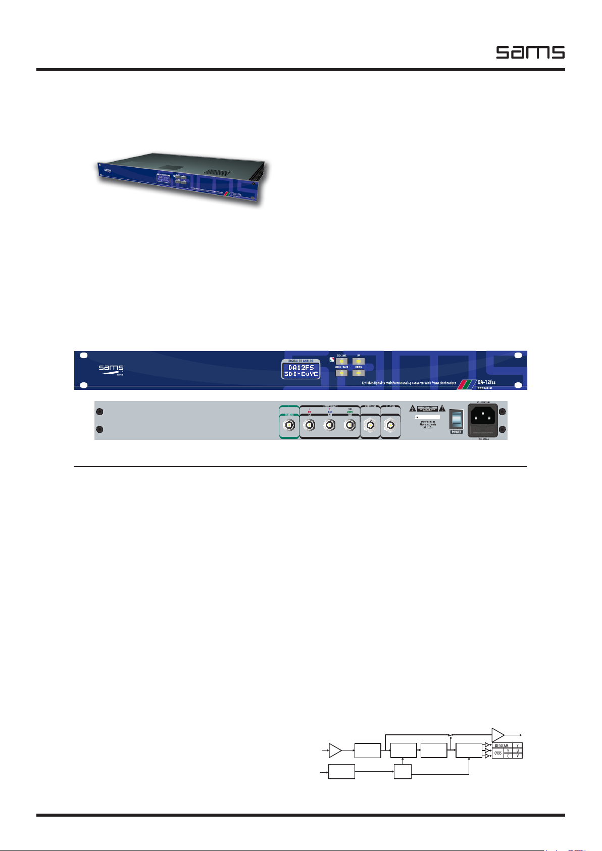
DA-12fs
SDI to multiformat analog converter with
frame sync
- Broadcast quality (12/10bit processing)
- Converts SDI to YUV, RGB, CVBS or YC
- Reclocked digital output
- Save 4 different presets
- Complete ProcAmp adjustment
- Jitter cleaner
- EDH processing
- PAL CVBS color framing and SC phase
- Pass, “Freezing” or broadcast test in the case of incorrect
video input
- Integrated Test Generator (Black, Color Bar)
- Easy setup with local control and LCD display
POWER
- Voltage: ........................................................... 2 x 12V AC
- Power: .........................................................................8W
TEMPERATURE
- Performance: .......................................................... 5-40°C
- Operating: .............................................................. 0-50°C
DA-12fs converts SDI to composite or component analog video. DA-12fs have a frame synchronizer that asynchronous video signal
recorded in the memory and reads it synchronized with an external reference, as well as other settings. It is useful for sychronizing
large number of external signals with signals from the TV station, or the capture of material from an amateur into a professional
format. With both available, composite and component (Y, Cr, Cb or RGB or YC) outputs, this unit is ideal for converting all types
of analog video. Complete ProcAmp output signal controls are provided for all output formats with adjustments: Horizontal and
Vertical Blanking, Horizontal and Vertical Position, SC Phase, Color Framing, Luma, Color, Pedestal, Sharpness, YC Delay etc. The
module is placed in the SRU-306 3RU chassis with capacity of 6 modules. Also, the device is available in standalone version.
BLOCK DIAGRAM