manuals.online logo
Brands
  1. Home
  2. •
  3. Brands
  4. •
  5. Samson
  6. •
  7. Microphone System
  8. •
  9. Samson VLX User manual

Samson VLX User manual

\A_X
\4-X
WIRELESS
SYSTEM
OWNER
’
S
MANUAL
Samson
cares
about
the
environment
SAMSON
THE
WIRELESS
FUTURE"
J
y
n
y
/
V
v
/
/
X
X
/
Y
\
/
/I/
/]/
/
zf
\
7
looting
X
I
'X
/
Produced
by
On
The
Right
Wavelength
for
Samson
Technologies
Coq>
-
X
/
/
X
Copyright
996,
Samson
Technologies
Corp.
z
/
z
X
ndix
C
At
ndix
D:
R«
R22/22X
/
Printed
April,
996
Appen
X
16
\
X
X
X
Wiring
Guide
nd
Ch rt
27
i
wx
i
M.
"[x
True
Diver
\
\
x
J
I
f
/
/
/
/
em
l'
X
\
/
/
Samson
Technologies
Corp.
575
Underhill
Blvd.
P.O.
Box
903
Syosset,
NY
79 -903
Phone:
-800-3-SAMSON
( -800-372-6766)
Fax:
5 6-364-3888
/
A
y
\
/'
■
I
/
XX-
x
W'
'X
x.
-X
-4
!
Iill-
z
A
xy
Xx
nd
Using
the
TD
Syste
“
-
*•
®
24
X
AX..
Guider
/
v
Appendix
B
Appem
UP
4
x
lie
S mson
Noise
Suppress
23
X
<X
X
\\\'"v
\
x
z
/■
\
/
/
V
\Z
X
--
/
>
VT2L
Mu
tip
n
X
X
X
X.
2HI
X
X
\
\
the
VI
Vp2
Rear
Panel
/
I/22X
Front
P^tnel
VT2UVT2
g
A
ipendix
A:
26
xjx
MX
/
y
/
,
K
x
I
\
p
nd
U
ix
C:
About
D:
R ck-Mounting
Appendix
E:
Not
All
B tteries
/
/
/
/
/
X
4
x
\
\
A
Are
Cre ted
Equ
Gloss ry
of
Terms
34
Specific tions
36
\
X.
'
\
X
^X
Z
x
Frequency
Conversion
h
l
XL
X.
X
Xl\
X
X
X
X
X
X
X
/
S<
X
/
\
V
/
7
/
4
/
/
/
in
TVX
x
Z
Z
V
Panel.
0
\
\
/
y
//
/
32
/
/
/
/
XX
X
XX
1
A
x
•A
X
X
■Y
/\
X
X
/
/
i/
I
x
/
p
/
/
y
1
'If
1
X
7
i
'
/
VLX/VL
A
J
7
1
.
ix
A
7-,
_ ____
p
—
_
/
Circuitry
23
XT
i
^
ii
I
X
Apper
Ch rt
T b/e
of
Contents
VR2:
I2/22X
Rear
14>
About
th
iiitry
2
ble-sh<
Tours
5
\
■ 2
Front
Panel
5
!2/2:
’
2/2;
bv
X
Y
A
\
\
z
i^tiiQiixi
em
Fe ture
Introduction
Introduction
£j-
~
^3
B
S
'ir
>r
o-=
0-~
2
*
VLX
TD
systems
purchased
with
the
VT2G
instrument
belt-pack
transmitter
include
a
VR22
receiver;
all
other
VLX
TD
systems
include
a
VR22X
receiver;
these
two
models
differ
only
in
that
the
VR22X
provides
a
rear-panel
balanced
XLR
output
ack.
SPECIAL
NOTE:
Should
your
unit
ever
require
servicing
a
Return
Authorization
number
(RA)
is
necessary.
Without
this
number
the
unit
will
not
be
accepted.
Please
call
Samson
at
1-800-372-6766
for
a
Return
Authorization
number
prior
to
shipping
your
unit.
Please
retain
the
original
packing
materials
and
if
possible
return
the
unit
in
its
original
carton
and
packing
materials.
In
this
manual
you
’
ll
find
a
more
detailed
description
of
the
features
of
your
VLX
/
VLX
TD
system
as
well
as
a
guided
tour
through
all
compo

nents
step-by-step
instructions
for
setting
up
and
using
your
system
information
about
Samson
Noise
Suppression
trouble-shooting
tips
a
frequency
conversion
chart
a
technical
description
of
True
Diversity
rack-mounting
instructions
a
glossary
of
terms
and
full
specifications.
You
’
ll
also
find
a
warranty
card
enclosed
—
don
’
t
forget
to
fill
it
out
and
mail
it
in!
This
will
enable
you
to
receive
online
technical
support
and
will
allow
us
to
send
you
updated
information
about
these
and
other
Samson
products
in
the
future.
The
VLX
and
VLX
TD
VHF
Wireless
Systems
differ
in
that
the
VR2
receiver
provided
in
the
VLX
system
utilizes
non-diversity
technology
incorporating
a
single
antenna
for
ease
of
use
while
the
VR22
and
VR22X
receivers*
provided
in
the
VLX
TD
system
utilize
a
system
called
“
Microprocessor
True
Diversity
”
(patent-pending).
In
this
system
a
single
chassis
(the
VR22/22X)
houses
two
antennas
(called
“
Antenna
A
”
and
“
Antenna
B
”
)
and
one
receiver
circuit.
A
built-in
computer
chip
con

tinuously
scans
RF
signals
from
the
two
antennas
and
determines
which
one
has
the
clearest
and
strongest
reception
automatically
(and
silently)
switching
that
signal
to
the
receiver.
This
allows
you
to
maintain
the
wireless
communication
link
over
a
broader
range
than
would
be
allowed
by
a
receiver
utilizing
a
single
antenna
and
also
reduces
inter

ference
and
phase
cancellation
problems.
In
addition
special
sample-
and-hold
linking
circuitry
ensures
that
correct
phase
correlation
is
main

tained
at
all
times
with
no
noise
or
pops
during
antenna
switching.
Both
systems
utilize
the
Samson
Noise
Suppression
system
and
both
provide
excellent
performance
and
the
highest
quality
audio
fidelity.
Congratulations
on
purchasing
the
Samson
VLX
/
VLX
TD
VHF
Wireless
System!
Although
this
product
is
designed
for
easy
operation
we
sug

gest
you
first
take
some
time
to
go
through
these
pages
so
you
can
fully
understand
how
we
’
ve
implemented
a
number
of
unique
features.
Every
wireless
system
consists
of
at
least
two
components
—
a
transmit

ter
and
a
receiver
both
of
which
must
be
tuned
to
the
same
channel
(that
is
the
same
radio
frequency)
in
order
to
operate
correctly.*
The
Samson
VLX
/
VLX
TD
system
you
have
purchased
contains
either
a
VR2
VR22
or
VR22X
receiver
and
either
a
VT2L
microphone
belt-pack
transmitter
(for
lavalier
microphone
and
headset
applications)
a
VT2G
guitar
belt-pack
transmitter
(for
instrument
applications)
or
a
VH2
hand

held
microphone
transmitter.
Here
’
s
an
illustration
that
shows
an
overview
of
our
system
design:
TTT
I
r\
>
/
Ml
\
I
(
0©
••
1
s
®
•
®
©
®
•
•
•
••
I'
1
m
/
/
*
Your
receiver
and
transmitter
have
been
factory
preset
to
utilize
the
same
channel.
A
listing
of
the
thirteen
available
channels
and
their
cor

responding
VHF
frequencies
can
be
found
on
page
26
of
this
manual.
1
t
®
System
Features
System
Features
II
3
*
We
recommend
the
use
of
the
Samson
RM22
adapter
for
this
purpose;
see
page
31
of
this
manual
for
rack-mounting
instructions.
•
The
VR22/22X
receiver
includes
a
pair
of
tuned
antennas,
specially
designed
to
maximize
the
effective
range
of
the
ireless
link..
•
The
VLX
system
incorporates
non-diversity
technology
for
simple,
reliable
operation.
The
VLX
TD
system
incorporates
Microprocessor
True
Diversity
technology,
hich
extends
the
effec
tive
range
of
the
system
and
also
reduces
potential
interference,
noise,
pops,
and
phase
cancellation
problems.
•
The
VH2
hand-held
microphone
transmitter
is
available
in
a
selection
of
popular
mic
capsules,
including:
•
The
VT2L,
VT2G
and
VH2
transmitters
all
utilize
internal
antennas
instead
of
the
bulky
external
antennas
used
by
many
competing
systems.
All
three
transmitters
provide
extended
18
hour
battery
life
and
po er
supplies
that
aren
’
t
fussy,
accepting
standard
9-volt
alkaline
batteries.
•
Built-in
Samson
Noise
Suppression
circuitry
in
both
the
transmitter
and
receiver.
This
ensures
clear,
transparent
sound
ith
an
absolute
minimum
of
background
noise
and
hiss.
•
Thirteen
different
available
channels,
designed
for
simultaneous
use.
This
means
that
you
can
use
multiple
VLX
/
VLX
TD
systems
(each
tuned
to
a
different
channel)
in
the
same
location
ithout
interference.
•
The
VT2L
and
VT2G
belt-pack
transmitter
is
extremely
light eight
(less
than
4
ounces
ith
a
9-volt
battery
installed).
The
VT2G
comes
pre ired
ith
permanent
connection
to
a
standard
1/4"
jack
(for
use
ith
instruments
such
as
electric
guitar
or
bass),
hile
the
VT2L
provides
a
S itchcraft
P3
mini-XLR
jack
for
connection
to
a
variety
of
popular
headsets
and
lavalier
microphones,
including:
Electro
Voice
ND
757A
N/DYM
Dynamic
Electro
Voice
ND
857
N/DYM
Dynamic
Samson
S11
Dynamic
Shure
SM58
Dynamic
Shure
SM85
Condenser
Shure
SM87
Condenser
•
The
VR22/22X
is
a
half-rack
unit
that
can
be
used
freestanding
or
can
be
mounted
in
any
standard
19"
rack,*
making
it
easy
to
integrate
into
any
traveling
or
fixed
installation
audio
system.
•
All
components
have
rugged
construction
that
ensures
reliable
operation
in
even
the
most
demanding
performance
environments.
•
The
VT2L,
VT2G
and
VH2
transmitters
all
provide
“
popless
”
muting
—
their
mute
function
turns
off
the
audio
signal
hile
leaving
the
carrier
signal
on.
The
Samson
VLX
/
VLX
TD
VHF
Wireless
System
utilizes
the
latest
advancements
in
ireless
communications.
Here
are
some
of
its
main
features:
I
1
*
Optimized
for
aerobics
orkouts,
this
headset
is
recommended
for
usage
in
high-humidity
environments
such
as
physical
fitness
centers.
4
AKG
C-410
headset
AKG
C-409
horn
microphone
Audio-Technica
ATM-75
headset
Audio-Technica
MT-350
lavalier
Audio-Technica
Pro-8HE
headset*
Audio-Technica
831
H-7
lavalier
Countryman
IsoMax
headset
Cro n
CM-311
/
CM-312
headset
Samson
ECM-40
lavalier
Sennheiser
MKE-2
lavalier
Sony
ECM-44
lavalier
Sony
ECM-55
lavalier
Sony
ECM-77
lavalier
I
Guided
Tour
-
VR2
Front
Panel
Guided
Tour
-
VR2
Front
Panel
1
ANT
OUTPUT
POWER
TXON
VOLUME
PEAK
t
o
o
+
SIGNAL
<
GROUND
s
32
4
5
2:
Power
LED
-
This
is
lit
whe ever
the
VR2
is
powered
o .
6
5
5:
Volume
control
-
This
k ob
determi es
the
level
of
the
audio
sig al
se t
from
the
VR2
output
jack
(see
#6
below).
3:
TX
On
LED
-
Whe
carrier
sig al
of
sufficie t
stre gth
is
bei g
received
by
the
VR2,
this
LED
is
lit.
4:
Peak
LED
-
This
LED
lights
whe
output
sig al
from
the
VR2
is
at
the
o set
of
clippi g
(that
is,
whe
it
is
o
the
verge
of
bei g
distorted).
If
you
see
this
light
duri g
operatio ,
move
the
micropho e
further
away
or
lower
the
output
level
of
your
i strume t
or
tra smitter.
For
more
i formatio ,
see
the
sectio
i
this
ma ual
e titled
“
Setti g
Up
a d
Usi g
the
VLX
/
VLX
TD
System
”
o
page
16.
1
:
Antenna
-
Duri g
ormal
operatio ,
this
should
be
fully
exte ded
a d
i
a
vertical
positio .
Do
not
substitute
a
third-party
receiver
a te a.
See
the
sectio
i
this
ma ual
e titled
“
Setti g
Up
a d
Usi g
the
VLX
/
VLX
TD
System
”
o
page
16
for
i formatio
about
a te a
positio i g.
:
Output
jack
-
Use
this
u bala ced
(-10
dB)
high
impeda ce
(5K
Ohm)
1/4"
jack
to
co ect
the
VR2
to
your
audio
equipme t.
Wiri g
is
as
follows:
+
SIGNAL
GROUND
SAMSON
\/l
—
X
\AFt2
n\
h
▲
DC12V
IN
VHF
FM
RECEIVER
Channel
13
Guided
Tour
-
VR2
Rear
Panel
1
w
2
1
©
2
4
3
5
6
4
2:
Power
LED
-
This
is
lit
whenever
the
VR22/22X
is
powered
on.
7
2:
DC
input
-
Connect
the
supplied
Sa son
AC300R
adapter
here.
WARNING:
Do
not
substitute
any
other
kind
of
power
adapter;
doing
so
can
cause
severe
da age
to
the
unit
and
will
void
your
warranty.
1:
Antennas
A
and
-
During
nor al
operation,
these
should
be
fully
extended
and
in
a
vertical
position.
Do
not
substitute
third-party
receiv
er
antennas.
See
the
section
in
this
anual
entitled
“
Setting
Up
and
Using
the
VLX
/
VLX
TD
Syste
”
on
page
16
for
infor ation
about
antenna
positioning.
1
:
Mute
control
-
This
control
deter ines
the
axi u
range
of
the
VR2
before
audio
signal
dropout.
It
should
nor ally
be
left
at
its
factory
setting.
For
ore
infor ation,
see
the
“
Setting
Up
and
Using
the
VLX
/
VLX
TD
Syste
”
section
on
page
16.
VDCTO
□
Guided
Tour
-
VR22/22X
Front
Panel
3:
Peak
LED
-
This
LED
lights
when
output
signal
fro
the
VR22X
is
clipping
(distorted).
If
you
see
this
light
during
operation,
ove
the
icrophone
further
away
or
lower
the
output
level
of
your
instru ent
or
trans itter.
For
ore
infor ation,
see
the
section
in
this
anual
entitled
“
Setting
Up
and
Using
the
VLX
I
VLX
TD
Syste
”
on
page
16.
8
J
ELJ
MICROPROCESSOR
TRUE
DIVERSITY
(Channel
13)
•
------------
•-
w
[
7TTT
3
2
1
+
SIGNAL
<
GROUND
3
-SIGNAL
1
GROUND
e
0
TO
MIXER
2
+
SIGNAL
10
9
1
:
DC
input
-
Connect
the
s pplied
Samson
AC300R
adapter
here.
WARNING:
Do
not
s bstit te
any
other
kind
of
power
adapter;
doing
so
can
ca se
severe
damage
to
the
nit
and
will
void
yo r
warranty.
*
If
your
VLX
TD
system
has
a
VR22X
receiver,
both
the
front
panel
1/4"
unbalance
an
rear
panel
XLR
balance
outputs
can
be
use
simultaneously
if
necessary.
6:
Output
jack*
-
Use
this
nbalanced
(-10
dB)
high
impedance
(5K
Ohm)
1/4"
jack
to
connect
the
VR22/22X
to
yo r
a dio
eq ipment.
Wiring
is
as
follows:
3:
XLR
Output
jack
(VR22X
only)
-
Use
this
electronically
balanced
low
impedance
(600
Ohm)
XLR
jack
to
connect
the
VR22X
to
professional
(+4
dBv
or
-30
dBm)
a dio
eq ipment.*
Pin
wiring
is
as
follows:
2:
M te
control
-
This
control
determines
the
maxim m
range
of
the
VR22X
before
a dio
signal
dropo t.
It
sho ld
normally
be
left
at
its
factory
setting.
For
more
information,
see
the
“
Setting
Up
and
Using
the
VLX
/
VLX
TD
System
”
section
on
page
16.
*
If
your
VLX
TD
system
has
a
VR22X
receiver,
both
the
rear
panel
XLR
balance
an
front
panel
1/4"
unbalance
outputs
can
be
use
simulta

neously
if
necessary.
:
LEDs
-
When
signal
is
being
received,
one
of
these
LEDs
will
be
lit,
showing
yo
whether
signal
from
either
the
“
A
”
or
“
B
”
antenna
is
c rrently
being
sed.
A
comp ter
chip
inside
the
VR22/22X
constantly
scans
the
two
and
a tomatically
selects
whichever
is
receiving
the
strongest,
clearest
signal.
This
“
Microprocessor
Tr e
Diversity
”
switching
is
completely
ina dible,
and
it
effectively
increases
overall
range
while
red cing
potential
interference
and
phase
cancellation
problems.
For
more
information,
see
Appendix
C
(
“
Abo t
Tr e
Diversity
”
)
on
page
28
in
this
man al.
Guided
Tour
-
VR22/22X
Rear
Panel
5:
Volume
control
-
This
knob
determines
the
level
of
the
a dio
signal
sent
from
the
VR22/22X
o tp t
jack(s)
(see
#6
below
and
#3
on
the
next
page).
+
SIGNAL
~cn^~
J]
□
an}
GROUND
Guided
Tour
-
VR22/22X
Front
Panel
\
-
/
z
-
SAMSON
MODEL
NO.
VR22X
.
-
CCRVR22X
I
°C
12VINPUT
--------
'
PATENT
PENDING
H
H
Guided
Tour
-
VT2L
/
VT2G
Guided
Tour
-
VT2L
/
VT2G
2 3
4
1
® ©
(Channel
13)
(Channel
13)
x.
y
6
5
7
y
y
FCC
ID
CCRVT-1
©
2:
Battery
LED
-
This
LED
is
an
indicator
of
batter
strength.
When
the
VT2L
I
VT2G
is
first
powered
on,
this
LED
will
light
for
about
two-
tenths
of
a
second
(if
the
batter
is
sufficientl
strong),
and
will
then
go
off.
When
batter
voltage
is
low,
this
LED
lights
steadil ,
indicating
that
the
batter
needs
to
be
replaced.
3:
ower
on-off
switch
-
Use
this
to
turn
the
VT2L
I
VT2G
on
or
off
(to
conserve
batter
power,
be
sure
to
leave
it
off
when
not
in
use).
WARNING:
Be
sure
to
mute
the
audio
signal
at
our
external
mixer
or
amplifier
before
turning
the
VT2L
/
VT2G
power
on
or
off,
or
an
audible
pop
ma
result.
4:
Input
connector
-
The
input
device
is
connected
here.
The
VT2L
is
supplied
with
either
a
lavalier
or
headset
microphone
(connected
via
a
Switchcraft
mini-XLR
jack,
as
shown
in
the
illustration
above),
while
the
VT2G
is
supplied
with
a
permanentl
connected
1/4"
jack
cable.
11
7:
lastic
screwdriver
-
Speciall
designed
for
use
in
adjusting
the
VT2L
/
VT2G
Level
control
(see
#8
on
the
next
page)
and/or
VR2
or
VR22/22X
receiver
Mute
control
(see
the
“
Guided
Tour:
VR2
[or
VR22/22X]
Rear
Panel
”
and
“
Setting
Up
and
Using
the
VLX
/
VLX
TD
S stem
”
sections
on
pages
7,
10
and
16
for
more
information).
12
1:
Mute
on-off
switch
-
When
set
to
the
“
Off
”
position,
audio
signal
is
transmitted.
When
set
to
the
“
On
”
position,
the
audio
signal
is
muted.
The
advanced
circuitr
in
the
VLX
/
VLX
TD
s stem
ensures
that
no
“
pop
”
or
“
thud
”
will
be
heard
during
muting.
Note
that
turning
this
on
does
not
turn
off
the
VT2L
/
VT2G
power
—
it
is
simpl
a
wa
to
tem

poraril
mute
the
transmission
of
audio
signal.
If
ou
don
’
t
plan
on
using
the
VT2L
I
VT2G
for
extended
periods,
turn
off
its
power
b
using
the
power
on-off
switch
(see
#3
below).
5:
Battery
door
-
Opening
the
VT2L
/
VT2G
batter
door
must
be
done
with
care.
See
the
“
Setting
Up
and
Using
the
VLX
/
VLX
TD
S stem
”
section
on
page
16
for
more
information.
6:
Battery
holder
-
Insert
a
standard
9-volt
alkaline
batter
here,
being
sure
to
observe
the
plus
and
minus
polarit
markings
shown.
We
recommend
the
Duracell
MN
1604
t pe
batter .
Although
rechargeable
Ni-Cad
batteries
can
be
used,
the
do
not
suppl
adequate
current
for
more
than
four
hours.
WARNING:
Do
not
insert
the
batter
backwards;
doing
so
can
cause
severe
damage
to
the
VT2L
/
VT2G
and
will
void
our
warrant .
VHF
BELTPACK
TRANSMITTER
Model
V
I
S^[L=
Technc
New
'i
ONoS-i
J
SOMSON
-lologies
Corp.
York
U.S.A./
POWE
R
mmO
|
[JJ
pFF
Guided
Tour
-
VH2
Guided
Tour
-
VT2L
/
VT2G
a
(
SAMSON
)
1
2
Model
x/n
OFF
ON
4
3
5
14
13
8:
Audio
Input
Level
control
(trimpot)
-
This
input
sensitivity
control
has
been
factory
preset
to
provide
optimum
level
for
the
particular
lavalier
or
headset
model
being
used
in
the
case
of
the
VT2G,
it
is
preset
for
optimum
instrument
level)
and
so
we
recommend
that
this
not
be
adjusted
manually.
If
necessary,
however,
you
can
use
the
supplied
plastic
screwdriver
to
raise
or
lower
the
VT2L
/
VT2G
input
level.
See
the
“
Setting
Up
and
Using
the
VLX
I
VLX
TD
System
”
section
on
page
16
for
more
information.
1
:
Audio
on-off
s itch
-
When
set
to
the
“
On
”
position,
audio
signal
is
transmitted.
When
set
to
the
“
Off
”
position,
the
audio
signal
is
muted.
The
advanced
circuitry
in
the
VLX
/
VLX
TD
system
ensures
that
no
“
pop
”
or
“
thud
”
will
be
heard
during
muting.
Note
that
turning
this
off
does
not
turn
off
the
VH2
power
—
it
is
simply
a
way
to
temporarily
mute
the
transmission
of
audio
signal.
If
you
don
’
t
plan
on
using
the
VH2
for
extended
periods,
turn
off
its
power
by
using
the
power
on-off
switch
see
#3
on
the
next
page).
AuoidX
\
EO/
f
A
94
BATT
J
/
ON
Ch
13
OFF
ON
£
eb
D@-
POWER
LEVEL
Guided
Tour
-
VH2
CHANNEL
NUMBER
I
TRUE
DIVERSITY
b
,
•
©
♦
16
15
i
~
?
i
a
VHF
FM
RE
CEIVER
The
basic
procedure
for
setti g
up
a d
usi g
your
VLX
/
VLX
TD
VHF
Wireless
System
takes
o ly
a
few
mi utes:
2:
Battery
LED
-
This
LED
is
a
i dicator
of
battery
stre gth.
Whe
the
VH2
is
first
powered
o ,
this
LED
will
light
for
about
two-te ths
of
a
seco d
(if
the
battery
is
sufficie tly
stro g),
a d
will
the
go
off.
Whe
battery
voltage
is
low,
this
LED
lights
steadily,
i dicati g
that
the
battery
eeds
to
be
replaced.
3.
Make
sure
the
Power
o -off
switch
i
your
VT2L
/
VT2G
beltpack
or
VH2
ha dheld
tra smitter
is
set
to
“
Off.
”
5:
Battery
holder
-
I sert
a
sta dard
9-volt
alkali e
battery
here,
bei g
sure
to
observe
the
plus
a d
mi us
polarity
marki gs
show .
We
recomme d
the
Duracell
MN
1604
type
battery.
Although
rechargeable
Ni-Cad
batteries
ca
be
used,
they
do
ot
supply
adequate
curre t
for
more
tha
four
hours.
ARNING:
Do
ot
i sert
the
battery
backwards;
doi g
so
ca
cause
severe
damage
to
the
VH2
a d
will
void
your
warra ty.
4:
Microphone
Input
Level
control
(trimpot)
-
This
i put
se sitivity
co trol
has
bee
factory
preset
to
provide
optimum
level
for
the
particular
micropho e
capsule
provided
with
your
VLX
/
VLX
TD
system
a d
so
we
recomme d
that
this
ot
be
adjusted
ma ually.
If
ecessary,
however,
you
ca
use
the
supplied
plastic
screwdriver
to
raise
or
lower
the
i put
level.
See
the
“
Setti g
Up
a d
Usi g
the
VLX
/
VLX
TD
System
”
sectio
o
page
16
for
more
i formatio .
3:
Power
on-off
switch
-
Use
this
to
tur
the
VH2
o
or
off
(to
co serve
battery
power,
be
sure
to
leave
it
off
whe
ot
i
use).
ARNING:
Be
sure
to
mute
the
audio
sig al
at
your
exter al
mixer
or
amplifier
before
tur i g
the
VH2
power
o
or
off,
or
a
audible
pop
may
result.
1.
For
the
VLX
I
VLX
TD
system
to
work
correctly,
both
the
receiver
a d
tra smitter
must
be
set
to
the
same
cha el.
Remove
all
packi g
materials
(save
them
i
case
of
eed
for
future
service)
a d
check
to
make
sure
that
the
supplied
VR2,
VR22
or
VR22X
receiver
a d
VT2L,
VT2G
or
VH2
tra smitter
are
set
to
the
same
cha el
(this
is
listed
o
the
top
of
the
VR2
or
VR22/22X,
o
the
belt
clip
of
the
VT2L
/
VT2G,
a d
o
the
bottom
of
the
VH2,
as
show
i
the
illustratio
below).
'z-'suoiS'x.\
<
ON
K_OF
e
V
Ch
13-^^BAT
t
\
Model
VHa
/
2.
O
the
VR2,
exte d
the
a te a
a d
place
it
i
a
vertical
positio .
O
the
VR22/22X,
fully
exte d
both
“
A
”
a d
“
B
”
a te as
a d
place
both
i
a
vertical
positio .
If
these
cha els
do
ot
match,
co tact
Samso
Tech ical
Support
at
1-800-372-6766.
Setting
Up
and
Using
the
VLX
/
VLX
TD
System
’
V"
V
•
—
•-
J
4
&
\
►
3
i
V
18
17
4a.
If
your
system
contains
a
VT2L
or
VT2G
transmitter,
locate
the
Open
arrow
on
the
rear
of
its
battery
door
and
press
down
and
forward
(away
from
the
belt
clip),
then
lift
up.
s
shown
in
the
illustration
below
;
the
battery
door
is
hinged
and
not
intended
to
be
removed
from
the
transmitter
case.
Please
use
care
when
opening
this
door
as
undue
force
will
destroy
the
hinge.
9.
Now
it
’
s
time
to
set
the
audio
levels.
Turn
on
your
connected
amplifier
and/or
mixer
but
keep
its
volume
all
the
way
down.
Next,
make
sure
that
your
transmitter
is
unmuted,
as
follows:
7.
Turn
the
Volume
knob
on
the
receiver
completely
counterclockwise.
Connect
the
supplied
C300R
adapter
to
the
DC
Input
on
the
rear
panel
of
the
receiver,
then
plug
the
C300R
adapter
into
any
standard
C
outlet.
The
“
Power
”
LED
will
light
up,
but
all
other
LEDs
will
remain
unlit.
5.
Place
a
fresh
9-volt
alkaline
battery
in
the
transmitter
battery
holder,
taking
care
to
observe
the
polarity
markings.
If
you
are
using
a
VT2L
or
VT2G
transmitter,
replace
the
battery
door
by
swinging
it
down
so
that
it
is
parallel
with
the
rear
panel
and
then
gently
pushing
upward
towards
the
belt
clip.
If
you
are
using
a
VH2
transmitter,
replace
the
bottom
section
of
the
microphone
by
sliding
it
on
and
then
screwing
it
back
on.
Whichever
transmitter
you
are
using,
leave
it
off
for
the
moment.
8.
Turn
on
the
power
to
the
VT2L,
VT2G
or
VH2
transmitter
(using
its
Power
on-off
switch);
its
“
Battery
”
LED
should
briefly
light
if
the
battery
is
good.
If
your
system
contains
a
VR2
receiver,
the
“
TXON
”
LED
on
its
front
panel
will
light.
If
your
system
contains
a
VR22
or
VR22X
receiver,
either
the
“
”
or
“
B
”
LED
on
the
front
panel
will
light
(depending
upon
which
antenna
is
receiving
the
stronger
signal).
Then
set
the
Volume
knob
on
the
receiver
to
the
3
o'clock
position
(this
is
unity
gain).
If
you
are
using
the
VH2
transmitter
or
if
you
are
using
the
VT2L
transmitter
with
a
connected
lavalier
microphone
or
headset,
speak
or
sing
into
the
mic
at
a
normal
performance
level
while
slowly
raising
the
volume
of
your
amplifier/mixer
until
the
desired
level
is
reached.
If
you
are
using
the
VT2G
transmitter
with
a
connected
instru

ment,
play
the
instrument
at
normal
performance
level
while
slowly
rais

ing
the
volume
of
your
amplifier/mixer
until
the
desired
level
is
reached.
If
you
are
using
a
VT2L
beltpack
transmitter
equipped
with
a
lavalier
6.
Make
the
physical
cable
connection
between
the
receiver
output
jack
and
the
audio
input
of
your
amplifier
or
mixer.
If
your
system
contains
a
VR22X
receiver
(provided
in
VLX
TD
systems
equipped
with
handheld,
lavalier
or
headset
microphones),
you
can
use
the
unbalanced
1/4
”
out

put
jack
on
the
front
panel
and/or
the
balanced
XLR
output
jack
on
the
rear
panel.
If
you
are
using
professional
(+4)
equipment,
the
balanced
XLR
jack
is
preferable
since
it
will
deliver
an
electromagnetically
cleaner
signal.
Leave
your
amplifier
(and/or
mixer)
off
at
this
time.
Setting
Up
and
Using
the
VLX
/
VLX
TD
System
Setting
Up
and
Using
the
VLX
/
VLX
TD
System
n~1
r
—
4b.
If
your
system
contains
a
VH2
transmitter,
unscrew
the
bottom
section
of
the
microphone
by
turning
it
counterclockwise
and
then
slide
it
off.
•
If
your
system
contains
a
VT2L
or
VT2G
transmitter,
set
its
Mute
switch
to
“
Off
”
•
If
your
system
contains
a
VH2
transmitter,
set
its
udio
switch
to
“
On
”
1
J
19
Note
that,
following
this
setup
procedure,
you
can
always
lower
the
Volume
knob
of
the
VR2
or
VR22/22X
below
the
3
o'clock
position
in
order
to
attenuate
the
output
signal
if
necessary.
away.
f
this
does
not
solve
the
problem,
use
the
supplied
plastic
screwdriver
to
turn
the
Level
control
(trimpot)
on
the
VT2L
slowly
counterclockwise
until
the
distortion
disappears.
11.
Conversely,
if
you
hear
a
weak,
noisy
signal
at
the
desired
volume
level,
again
make
sure
that
the
gain
structure
of
your
audio
system
is
correctly
set
(consult
the
owners
manual
of
your
mixer
and/or
amplifier
for
details).
f
it
is
and
the
signal
coming
from
the
receiver
is
still
weak
and/or
noisy,
do
the
following:
10.
f
you
hear
distortion
at
the
desired
volume
level,
first
check
to
see
whether
the
“
Peak
”
LED
on
the
receiver
is
lit.
f
it
is
not,
make
sure
that
the
gain
structure
of
your
audio
system
is
correctly
set
(consult
the
own

ers
manual
of
your
mixer
and/or
amplifier
for
details).
f
the
“
Peak
”
LED
is
lit,
do
the
following:
microphone,
note
that
correct
lavalier
placement
is
critical
to
sound
quality.
We
recommend
that
you
place
it
as
shown
in
the
illustration
below
—
as
close
to
your
mouth
as
possible
but
off
to
one
side
(to
minimize
nasality)
and
unobstructed
by
clothing.
Bear
in
mind
also
that
omni
microphones
(mics
which
pick
up
signal
from
all
directions)
are
more
prone
to
feedback
problems
than
unidirectional
(cardioid
or
supercardioid)
ones;
in
general,
you
can
avoid
feedback
by
taking
care
not
to
use
any
microphone
directly
in
front
of
a
PA
speaker
(if
this
is
unavoidable,
try
using
an
equalizer
to
attenuate
those
high-
or
mid

range
frequencies
which
are
causing
the
feedback
“
squealing
”
).
•
f
you
are
using
a
VT2L
transmitter
with
connected
lavalier
microphone
or
headset,
its
Level
control
has
been
factory
preset
to
provide
optimum
level
for
the
particular
lavalier
or
headset
model
being
used
and
so
no
adjustment
should
be
necessary.
Any
distortion
present
should
therefore
simply
be
a
matter
of
the
microphone
being
too
close
to
the
mouth;
try
moving
it
further
•
f
you
are
using
a
VH2
transmitter,
use
the
supplied
plastic
screwdriver
to
turn
its
Level
control
(trimpot)
slowly
counterclock
wise
(towards
the
“
Min
”
position)
until
the
distortion
disappears.
•
f
you
are
using
a
VT2L
transmitter
with
connected
lavalier
micro

phone
or
headset,
its
Level
control
has
been
factory
preset
to
provide
optimum
level
for
the
particular
lavalier
or
headset
model
being
used
and
so
no
adjustment
should
be
necessary.
Any
weakness
of
signal
should
therefore
simply
be
a
matter
of
the
microphone
being
too
far
from
the
mouth;
try
moving
it
closer.
f
this
does
not
solve
the
problem,
use
the
supplied
plastic
screwdriv

er
to
turn
the
Level
control
(trimpot)
on
the
VT2L
slowly
clockwise
until
the
signal
reaches
an
acceptable
level.
•
f
you
are
using
a
VH2
transmitter,
use
the
supplied
plastic
screw
driver
to
turn
the
Level
control
(trimpot)
on
the
transmitter
slowly
clockwise
(towards
the
“
Max
”
position)
until
the
signal
reaches
an
acceptable
level.
•
f
you
are
using
a
VT2G
transmitter
with
an
instrument
such
as
electric
guitar
or
bass,
lower
the
output
level
of
the
instrument
until
the
distortion
disappears.
Alternatively,
you
can
use
the
supplied
plastic
screwdriver
to
turn
the
Level
control
(trimpot)
on
the
VT2G
slowly
counterclockwise
until
the
distortion
disappears.
•
f
you
are
using
a
VT2G
transmitter
with
an
instrument
such
as
electric
guitar
or
bass,
raise
the
output
level
of
the
instrument
until
a
good
signal
is
achieved.
Alternatively,
you
can
use
the
supplied
plastic
screwdriver
to
turn
the
Level
control
(trimpot)
on
the
VT2G
slowly
clockwise
until
the
signal
reaches
an
acceptable
level.
20
*
I
Setting
Up
and
Using
the
VLX
/
VLX
TD
System
Setting
Up
and
Using
the
VLX
/
VLX
TD
System
TIP
(+
SIGNAL)
I
®
o
(U
1
22
21
Also,
do
not
connect
the
output
of
the
VR2
or
VR22/22
directly
to
the
line-level
input
of
signal
processors;
to
apply
effects
to
the
VR2
or
VR22/22
output
signal,
connect
signal
processors
to
mixer
insert
points
or
use
them
in
an
“
effects
loop
”
(send/return)
configuration.
Note
that,
following
this
setup
procedure,
you
can
always
raise
the
Volume
knob
of
the
VR2
or
VR22/22
above
the
3
o'clock
position
in
order
to
boost
the
output
signal
if
necessary.
NOTE:
The
VL
I
VL
TD
system
is
designed
to
replace
the
wire
that
is
used
in
wired
microphone
systems,
providing
a
gain
ratio
of
1
:
1.5.
Therefore,
when
using
a
mixer
that
provides
low
impedance
mic
inputs,
always
connect
the
VR2
or
VR22/22
to
those
mic
inputs,
as
opposed
to
line-level
(high
impedance)
inputs.
Because
mic
inputs
normally
utilize
LR-type
connectors
(as
opposed
to
the
1/4"
phone
connector
provided
by
the
VR2
or
VR22),
you
will
have
to
use
a
cable
that
has
a
male
LR
plug
at
one
end
and
a
1/4"
phone
plug
at
the
other
end,
wired
as
shown
below:
2
+
SIGNAL
1
GROUND
3
-SIGNAL
13.
When
first
setting
up
the
VL
I
VL
TD
System
in
a
new
environ

ment,
it
’
s
always
a
good
idea
to
do
a
walkaround
in
order
to
make
sure
that
coverage
is
provided
for
your
entire
performance
area.
Accordingly,
turn
down
the
level
of
your
audio
system
and
turn
on
both
the
transmit

ter
and
receiver.
Then,
with
the
transmitter
unmuted,
restore
the
level
of
your
audio
system
and
while
speaking,
singing,
or
playing
your
instru

ment,
walk
through
the
entire
area
that
will
need
to
be
covered.
If
you
have
a
VL
system,
as
you
do
so,
you
may
find
that
the
“
T ON
”
LED
on
the
VR2
receiver
occasionally
goes
off,
indicating
that
the
carrier
signal
being
received
from
the
transmitter
is
too
weak
to
provide
audio
output.
If
you
have
a
VL
TD
system,
you
may
find
that
the
“
A
”
and
“
B
”
LEDs
on
the
VR22/22
receiver
occasionally
switch
on
or
off,
always
showing
you
which
antenna
is
receiving
the
stronger
signal.
The
basic
rule
of
thumb
for
all
wireless
audio
systems
is
to
always
try
to
minimize
the
dis

tance
between
transmitter
and
receiver
as
much
as
possible
and
also
to
try
to
maintain
“
line
of
sight
”
between
the
two
(that
is,
the
person
using
the
transmitter
should
be
able
to
see
the
receiver
antennas).
The
idea
is
to
ensure
that
the
strongest
possible
signal
is
received
from
all
planned
transmission
points.
In
fixed
installations
such
as
A/V
or
corporate
conference
rooms
or
for
extended
range
applications
(where
the
transmitter
and
receiver
are
more
than
150
feet
apart),
it
may
be
desirable
to
angle
the
antennas
differently
from
their
vertical
position
or
to
install
the
receiver
in
the
same
room
as
the
transmitters
(and,
if
necessary,
to
extend
the
wiring
to
remote
audio
equipment).
For
more
information,
see
the
“
Trouble-shooting
”
section
on
pages
24
-
25
in
this
manual.
12.
Temporarily
turn
down
the
level
of
your
mixer/amplifier
system
and
turn
off
the
power
to
your
transmitter,
leaving
the
receiver
on.
Then
restore
the
previously
set
level
of
your
mixer/amplifier.
With
the
trans

mitter
off,
the
receiver
output
should
be
totally
silent
—
if
it
is,
skip
ahead
to
the
next
step.
If
it
isn
’
t
(that
is,
if
you
hear
some
noise),
you
may
need
to
adjust
the
VR2
or
VR22/22
rear
panel
Mute
control.
When
the
Mute
control
is
at
its
minimum
setting,
the
VL
/
VL
TD
system
always
provides
maximum
range
without
dropout;
however,
depending
upon
the
particular
environment
your
system
is
used
in,
you
may
need
to
reduce
that
range
somewhat
in
order
to
eliminate
band
noise
when
the
transmit

ter
is
turned
off.
To
do
so,
use
the
provided
screwdriver
to
rotate
the
Mute
control
completely
counterclockwise
(to
the
“
Min
”
position),
then
slowly
turn
it
clockwise
until
the
noise
disappears.
If
no
noise
is
present
at
any
position,
leave
it
at
its
fully
counterclockwise
“
Min
”
position
(so
as
to
have
the
greatest
overall
range
available).
If
you
have
followed
all
the
steps
above
and
are
experiencing
difficulties,
call
Samson
Technical
Support
(1-800-372-6766)
between
9
AM
and
5
PM
EST.
Setting
Up
and
Using
the
VLX
/
VLX
TD
System
Setting
Up
and
Using
the
VLX
/
VLX
TD
System
Connect
2|
these
together
SLEEVE
(GROUND
and
-
SIGNAL)
Trouble-shooting
Problem:
No
sound
3.
Is
the
battery
in
your
transmitter
fresh?
8.
If
you
’
re
using
a
mixer,
are
all
channels
out
of
solo
mode?
23
24
7.
Is
your
mixer/amplifier
system
po ered
on
and
is
its
level
control
or
fader
up
and
unmuted?
2.
Are
your
transmitter
and
receiver
both
po ered
on?
(The
Po er
LED
on
the
front
panel
of
the
receiver
ill
light
hen
it
is
po ered
on.)
1.
Are
your
transmitter
and
receiver
both
set
to
the
same
channel
number?
6.
Is
the
cable
connection
bet een
the
receiver
audio
output
and
your
mixer/amplifier
input
secure?
9.
If
you
’
re
using
a
VT2G
transmitter
ith
a
1/4"
instrument
jack
connection,
is
the
connection
to
the
instrument
secure?
Is
the
instrument
’
s
master
volume
up?
4.
If
you
are
using
a
VT2L
or
VT2G
transmitter,
is
its
Mute
s itch
set
to
“
Off
”
?
If
you
are
using
a
VH2
transmitter,
is
its
Audio
s itch
set
to
“
On
”
?
All
the
components
in
the
VLX
/
VLX
TD
VHF
Wireless
System
utilize
special
Samson
Noise
Suppression
circuitry
so
as
to
ensure
the
highest
fidelity
sound
ith
an
absolute
minimum
of
background
noise
and
hiss.
This
is
a
companding
system;
that
is,
the
signal
being
transmitted
has
its
dynamic
range
compressed
and
its
high
frequencies
boosted
(this
process
is
kno n
as
pre-emphasis
encoding),
and
the
signal
being
received
has
its
dynamic
range
expanded
and
high
frequencies
attenuated
in
an
exactly
opposite
ay
(this
process
is
kno n
as
de-emphasis
decoding).
The
pre-emphasis
encoding
process
is
automatically
carried
out
by
the
VT2L,
VT2G
and
VH2
transmitters
and
the
de-emphasis
decoding
process
is
automatically
carried
out
by
the
VR2,
VR22
and
VR22X
receivers.
5.
Is
the
Volume
knob
on
the
receiver
set
to
a
value
greater
than
minimum?
Solution:
Follo
these
step-by-step
trouble-shooting
suggestions
to
identify
the
problem.
If
the
ans er
to
any
of
these
questions
is
“
no,
”
you
’
ve
probably
located
the
difficulty.
When
orking
correctly,
the
“
TXON
”
LED
on
the
VR2
front
panel
or
either
the
“
A
”
or
“
B
”
LED
on
the
VR22/22X
front
panel
ill
be
lit
henever
both
the
receiver
and
transmit

ter
are
on.
If
both
units
are
on
and
neither
of
these
LEDs
is
lit,
start
ith
question
1
and
ork
your
ay
through
this
list
in
order.
If
the
VR2
“
TXON
”
or
either
the
VR22/22X
“
A
”
or
“
B
”
LED
is
lit,
you
can
skip
ahead
to
question
4
and
then
ork
your
ay
through
this
list
in
order.
About
the
Samson
Noise
Suppression
Circuitry
Trouble-shooting
25 26
Also,
if
the
VR22/22X
receiver
is
mounted
in
a
rack
near
equipment
such
as
computers,
hard
drives,
or
electronic
keyboards
or
tone
generators,
intermodulation
noise
can
occur
Try
moving
the
receiver
5
or
6
feet
away
from
such
equipment
—
if
the
noise
disappears,
you
’
ve
located
(and
solved)
the
problem
Solution!
Try
changing
the
position
of
the
receiver
antenna(s)
or
try
relocating
the
transmitter
and/or
receiver
In
general,
it
’
s
best
to
minimize
the
distance
between
the
two
and
also
to
try
to
keep
a
clear
line
of
sight,
so
that
the
person
wearing
or
using
the
transmitter
can
always
see
the
receiver
If
the
answer
to
all
these
questions
is
“
yes
”
and
you
still
hear
no
sound,
call
Samson
Technical
Support
at
1-800-372-6766
between
9
AM
and
5
PM
EST
Bear
in
mind
also
that
both
the
receiver
and
transmitter
in
the
VLX
/
VLX
TD
System
contain
delicate
components
called
crystals.
As
their
name
implies,
these
are
subject
to
damage
when
the
unit
is
subjected
to
extreme
stress
(such
as
being
dropped
from
a
significant
height),
so
treat
your
receiver
and
transmitter
with
the
kind
of
TLC
you
normally
reserve
for
loved
ones!
Solution:
This
will
occur
if
two
or
more
users
are
using
VLX
/
VLX
TD
(or
other
wireless)
systems
at
the
same
location
and
more
than
one
system
is
set
to
the
same
channel
Each
VLX
/
VLX
TD
user
at
a
given
location
must
be
using
a
discrete
transmitter
and
receiver
set
to
a
different
channel.
Problem:
Sound
fades
as
performer
moves
around
(sound
dropout)
Channel
0
1
2
3
_
5
6
7
8
9
10
11
12
13
Problem:
Distorted
sound
(Cross-modulation
interference)
Frequency
174 6
MHz
177 6
MHz
181 6
MHz
183 6
MHz
190 6
MHz
192 6
MHz
195 6
MHz
196 6
MHz
199 6
MHz
202 2
MHz
208 2
MHz
211 2
MHz
213 2
MHz
Appendix
A:
requency
Conversion
Chart
Appendix
B:
VT2L
Multipin
Appendix
C:
About
True
Diversity
Wiring
Guide
and
Chart
1
2
3
4
SW TCHCRAFT
TA3F
Space
Diversity
MANUFACTURER
MODEL
PIN
2
PIN
3
AKG
C409
WHITE
JUMP
TO
PIN
2
AKG
C410
WHITE
JUMP
TO
PIN
2
AUDIO
TECHNICA
AT831
JUMP
TO
PIN
2
RED
X
2
AUDIO
TECHNICA
ATM71
JUMP
TO
PIN
2
RED
X
2
AUDIO
TECHNICA
ATM75
RED
x
2
JUMP
TO
PIN
2
AUDIO
TECHNICA
ATPRO8HE
N/C
RED
X
2
AUDIO
TECHNICA
HIELD
WHITE
JUMP
TO
PIN
2
CROWN
RED
JUMP
TO
PIN
2
ONY
ECM44
JUMP
TO
PIN
2
RED
ONY
ECM55
JUMP
TO
PIN
2
RED
Antenna
A
ONY
ECM77
JUMP
TO
PIN
2
RED
ONY
ECM
144
AF
OUTPUT
WHITE
JUMP
TO
PIN
2
P
ENNHEI ER
MKE2
JUMP
TO
PIN
2
RED
NOI E
REDUCTION
V
ENNHEI ER
MKE40
JUMP
TO
PIN
2
RED
Adlonna
B
ENNHEI ER
MKE48
JUMP
TO
PIN
2
RED
FO TER
ECM40
HIELD
JUMP
TO
PIN
2
WHITE
COUNTRYMAN
I OMAX
HIELD
WHITE
JUMP
TO
PIN
2
GUITAR
HIELD
N/C
AUDIO
PIN
INFORMATION
GROUND
+Vdc
AUDIO
28
27
WITCHCRAFT
TA3F
YELLOW
x
2
HIELD
YELLOW
x
2
HIELD
YELLOW
x
2
HIELD
HIELD
BLUE
HIELD
WHITE
HIELD
WHITE
HIELD
WHITE
HIELD
HIELD
BLUE
>
►
Procedure
for
wiring
VT2L
connector:
Unscrew
rubber
boot
1
and
pass
wire
through
1
and
2.
older
wire
to
3
after
removing
from
4
(use
chart
above).
Reinsert
3
to
4
with
attached
wire
(3
is
keyed
to
fit
4).
Plug
2
into
3
again
(2
is
keyed
to
3)
and
crimp
wire.
Rescrew
rubber
boot
1
to
4.
YELLOW
X
2
HIELD
HIELD
BLUE
HIELD
WHITE
RECEIVER
CIRCUIT
RECEIVER
CIRCUIT
WITCHING
CIRCUIT
The
advantage
to
this
kind
of
system
is
that
the
effective
range
is
greatly
expanded
and
many
potential
interference
problems
are
eliminated,
since,
when
one
antenna
is
partially
obstructed
or
is
receiving
interfer

ence,
the
other
may
not
be.
The
disadvantage
is
that
using
two
separate
receivers
can
cause
phase
differential
problems
and
such
systems
tend
to
be
more
cumbersome
and
expensive.
*
The
VT2L,
VT2G
and
VH2
transmitters
utilized
by
the
VLX
TD
system
all
have
internal
antennas.
The
two
basic
components
in
any
wireless
system
are
a
transmitter
and
receiver,
each
with
its
own
antenna(s).*
The
effective
range
of
the
system
is
largely
determined
by
how
much
area
between
the
transmitter
antenna
and
receiver
antenna
is
physically
unobstructed.
Because
most
environments
contain
numerous
obstructions
(thus
limiting
the
effective
range),
manufacturers
of
wireless
systems
have
in
recent
years
evolved
a
technology
called
“
pace
Diversity,
”
as
shown
in
the
illustration
below.
In
these
systems,
a
single
chassis
houses
two
receivers,
both
tuned
to
the
same
channel
(that
is,
radio
frequency)
as
the
transmitter,
but
with
each
receiver
having
its
own
antenna
(usually
called
“
Antenna
A
”
and
“
Antenna
B
”
).
A
switching
circuit
then
continuously
scans
the
two
receiver
signals,
automatically
routing
the
stronger
of
the
two
to
the
noise
reduction
decoder
(if
one
is
used)
and
final
audio
output:
As
described
in
the
Introduction
to
this
manual,
the
VLX
TD
VHF
Wireless
ystem
utilizes
a
technological
breakthrough
called
“
Microprocessor
True
Diversity
”
(the
VLX
ystem
uses
Non-Diversity
technology).
In
this
section,
we
’
ll
take
a
closer
look
at
how
Diversity
systems
work.
MT350
CM311E
CM312E
HIELD
RED
PIN
1
HIELD
RED
9
sw
Appendix
C:
About
True
Diversity
Appendix
C:
About
True
Diversity
Antenna
True
Diversity
Microprocessor
True
Diversity
Y
Antenna
A
-►I
NOISE
REDUCTION
[■
Q)
AF
OUTPUT
Antenna
A
ISOLATION
AMP
Antenna
B
SW
Co;
?
a
I
-{
Antenna
B
ISOLATION
AMP
29
30
-►]
s
/
h
[-►[
T e
end
result
is
extended
range,
crystal-clear
sound,
and
t e
virtual
elimination
of
p ase
correlation
and
spurious
noise
problems.
RECEIVER
CIRCUIT
An
alternative
design
is
called
“
Antenna
True
Diversity,
”
as
s own
in
t e
illustration
below.
Here,
instead
of
aving
two
receivers,
a
single
c assis
ouses
two
antennas
and
a
single
receiver
circuit.
A
circuit
t en
continuously
scans
t e
signal
coming
from
Antenna
A.
W en
t is
signal
drops
below
a
predetermined
t res old
level,
signal
from
Antenna
B
is
added
to
t e
mix
(after
first
being
p ase
s ifted
by
180°
in
order
to
avoid
p ase
cancellation
problems).
From
t ere,
t e
signal
from
eit er
Antenna
A
alone
(if
it
is
strong
enoug )
or
Antenna
A
plus
Antenna
B
(if
t e
Antenna
A
signal
is
too
weak)
is
routed
to
t e
noise
reduction
decoder
(if
one
is
used)
and
final
audio
output.
Your
VLX
TD
system
utilizes
a
completely
new
kind
of
tec nology
called
“
Microprocessor
True
Diversity,
”
w ic
yields
significantly
improved
per

formance
over
ot er
True
Diversity
systems.
T e
illustration
below
s ows
ow
it
works.
Here,
a
ig -speed
computer
c ip
(a
microproces

sor)
continuously
scans
t e
RF
signals
coming
from
two
discrete
anten
nas,
automatically
(and
silently)
routing
t e
stronger
and
clearer
signal
to
t e
receiver
circuit
(t ese
reroutings
can
occur
as
frequently
as
200,000
times
a
second!).
Isolation
amplifiers
ensure
t at
t ere
is
no
close-field
interference
between
t e
two
antennas
and
a
sample-and- old
linking
circuit
automatically
eliminates
audio
spikes
or
pops
caused
by
p ase
differential
during
antenna
switc ing,
providing
a
smoot ,
glitc -free
tran

sition
between
signals.
From
t e
sample-and- old
circuit,
t e
signal
is
routed
to
a
Samson
Noise
Suppression
decoder
(so
as
to
minimize
any
background
noise
and
iss)
and
on
to
t e
final
audio
output
jack.
MIXING
SW
'
Q
T e
problem
wit
t is
kind
of
system
is
t at,
since
t e
two
antennas
are
in
p ysically
different
areas
(even
t oug
just
a
few
inc es
apart),
t ere
is
a
certain
delay
time
between
t e
two,
w ic
can
cause
a
p ase
difference
between
t e
two
signals.
T is
can
result
in
a
receiving
condition
w ic
is
actually
worse
t an
if
only
a
single
antenna
were
being
used.
Moreover,
a
spike
noise
can
appear
in
t e
output
signal
w enever
t e
system
switc es
to
add
in
signal
from
Antenna
B
—
particularly
w en
t e
transmitter
is
at
a
long
distance
from
t e
receiver.
Eliminating
t ese
glitc es
in
t e
sound
usually
involves
a
temporary
muting
or
gating
of
t e
audio
signal.
180°
PHASE
SHIFT
RECEIVER
CIRCUIT
▼
SWITCHING
CIRCUIT
AF
OUTPUT
NOISE
SUPPRESSION
SWITCHING
CIRCUIT
CPU
A
f|f|
I
1
V
V
Battery
#1
Battery
#2
Battery
#3
32
31
SAMSON
\n->c
m
i
*
When
using
rechargeable
batteries,
we
recommend
VARTA
batteries
as
they
will
charge
to
the
proper
amperage.
Putting
matchbooks
or
paper
in
the
battery
compartment
as
a
spacer
can
also
cause
long
term
battery
terminal
damage.
Most
problems
with
a
wireless
unit
cutting
out
”
are
caused
by
these
factors
and
can
usually
be
remedied
with
a
tweezer
or
a
small
screwdriver.
If
you
use
a
larger
battery,
we
recommend
that
you
continue
using
that
brand
in
order
to
maintain
a
positive
fit.
I
Larger
batteries
(Battery
#2
and
#3
in
the
illustration
below)
can
actually
cause
long
term
damage
to
your
battery
terminal
fit,
break
battery
doors,
and
push
in
the
battery
terminals
past
the
point
of
spring-back.
A
C
..........
“
E
2"
1.75"
1.5"
1.25"
1"
.75"
.5"
.25"
I
1,75'
1.5'
1,2b'
1'
,7b'
.5'
,2b'
I
T
i
Appendix
E:
Not
All
Batteries
Are
Created
Equal
The
transmitter
provided
with
your
Samson
VLX
I
VLX
TD
VHF
Wireless
System
requires
a
9-volt
battery
for
power,
but
there
can
be
substantial
differences
between
different
brands
of
batteries.
In
fact,
out
of
all
the
major
brand
batteries
currently
on
the
market,
only
the
DURACELL
MODEL
MN
1604
(as
indicated
by
Battery
#1
in
the
illustration
below)
will
fit
correctly,
since
the
VT2L/VT2G/VH2
battery
compartment
is
designed
to
accommodate
its
precise
dimensions.*
Appendix
D:
Rack-Mounting
t e
VR22/22X
The
VR22/22X
receiver
can
be
used
either
freestanding
or
mounted
in
a
standard
19"
rack.
If
rackmounted,
it
is
designed
to
fit
into
the
Samson
RM22
rack
adapter,
which
takes
a
single
rack
space.
The
illustration
below
shows
how
the
VR22/22X
is
to
be
mounted
into
the
RM22:
Glossary
of
Terms
© ©
y
Fig.
A
Fig.
B
Fig.
C
Fig.
D
33
To
prevent
the
pushing
in
of
battery
terminals
caused
by
the
use
of
improperly
sized
batteries,
Samson
can
provide
you
free
of
charge
with
square
rubber
pads
that
can
be
installed
on
the
battery
terminals
of
your
VT2L/VT2G/VH2
transmitter.
To
request
a
set,
just
call
us
at
1-800-3-SAMSON.
NOTE:
Battery
terminals
should
be
cleaned
periodically
to
insure
good
contact.
Use
a
pencil
eraser
or
some
other
soft
abrasive
material,
as
shown
in
Figure
D.
To
install
these
rubber
pads:
1.
Pull
up
the
battery
terminals
to
approximately
90°
(Figure
A).
2.
Peel
the
backing
off
the
rubber
pad
in
order
to
expose
the
adhesive
(Figure
B).
3.
Press
the
rubber
pad
in
place
under
the
lip
of
the
outstretched
battery
terminal
(Figure
C).
4.
Carefully
push
the
terminals
back
into
place.
Appendix
E:
Not
All
Batteries
Are
Created
Equal
AF
-
Short
for
“
Audio
Frequency.
”
Audible
-
A
sound
that
we
can
hear,
generally
in
the
20
Hz
-
20
kHz
frequency
range.
Carrier
-
An
inaudible
high-frequency
radio
signal
that
is
continuously
modulated
by
an
audible
signal
(it
therefore
is
said
to
“
carry
”
the
audible
signal).
Channel
-
In
wireless
transmission,
refers
to
a
particular
radio
frequency.
Demodulation
-
The
process
of
removing
the
carrier
signal
and
thereby
restoring
the
original
audible
signal.
Frequency
-
Refers
to
the
number
of
wavecycles
occurring
per
second.
Audible
frequencies
are
in
the
range
20
Hz
-
20
kHz;
radio
frequencies
are
considerably
higher.
eadset
-
A
“
hands-off
”
microphone
worn
with
a
headband.
ertz
( z)
-
A
unit
of
frequency
measurement
denoting
one
wavecycle
per
second.
Inaudible
-
A
sound
that
we
cannot
hear.
Radio
waves
(which
have
frequencies
ranging
from
the
tens
of
thousands
to
millions
of
waves
per
second)
are
all
inaudible.
Kilo ertz
(k z)
-
A
unit
of
frequency
measurement
denoting
one
thousand
wavecycles
per
second.
Lavalier
-
A
“
hands-off
”
clip-on
mini-microphone.
Mega ertz
(M z)
-
A
unit
of
frequency
measurement
denoting
one
million
wavecycles
per
second.
Microprocessor
True
Diversity
-
An
advanced
wireless
reception
technology
(utilized
by
the
VLX
TD
System)
by
which
a
single
chassis
houses
two
discrete
antennas
(with
both
tuned
to
the
same
frequency)
and
a
receiver
circuit.
A
built-in
computer
chip
then
continuously
scans
the
two
antennas
and
determines
which
one
has
the
clearest
and
strongest
reception,
automatically
(and
silently)
switching
that
signal
to
the
receiver
circuitry.
The
result
is
that
the
wireless
communication
link
can
be
maintained
over
a
broader
area
range
than
would
be
allowed
by
a
receiver
utilizing
a
single
antenna.
In
addition,
the
provision
of
Isolation
amplifiers
and
a
sample-and-hold
linking
circuit
results
in
the
reduction
of
interference
and
audible
pops
and
clicks.
Modulation
-
The
process
by
which
one
signal
is
continuously
affected
by
another.
Noise
Suppression
-
A
process
by
which
the
level
of
extraneous
noise
or
hiss
in
a
signal
is
reduced
considerably.
The
VLX
/
VLX
TD
System
utilizes
the
Samson
Noise
Suppression
system.
34
Channel
2
)
■
<>
„
I
MH|
Glossary
of
Terms
Specifications
VH2
36
35
Number
of
Channels
Type
of
Reception
Signal
Sensitivity
25
Milliamps
Ma .
27
Milliamps
Ma .
Receiver
(VR2,
VR22,
VR22X):
Receive
Frequency
Range
Internal
Oscillators
Stability
Transmitter
(VT2L,
VT2G
and
VH2):
OSC
System
RF
Power
Antenna
Type
Transmit
Frequency
Range
Power
On/Off,
Mute
On/Off,
Level
Control
(Trimpot)
Power
On/Off,
Audio
On/Off,
Level
Control
(Trimpot)
Battery
low
Non- iversity
-
A
wireless
reception
technology
(utilized
by
the
VLX
System)
whereby
a
receiver
uses
a
single
antenna.
Receiver
-
A
component
that
receives
a
modulated
radio
signal
and
reconstructs
the
original
audible
signal
by
utilizing
demodulation.
RF
-
Short
for
“
Radio
Frequency.
”
Transmitter
-
A
component
that
transmits
an
audible
signal
by
using
it
to
modulate
a
high-frequency
inaudible
carrier
signal.
VHF
(Very
High
Frequency)
-
Refers
to
radio
waves
in
the
30
-
300
megaHertz
range.
VU
-
Short
for
“
Volume
Unit.
”
A
unit
of
measurement
utilized
by
audio
devices
that
denotes
relative
signal
strength.
0
VU
is
generally
taken
to
indicate
unity
gain
(no
boost
or
attenuation).
Wave
-
Refers
to
the
transference
of
energy
in
a
regular,
back-and-forth
vibration.
Wavecycle
-
One
single
backwards-and-forwards
motion
of
a
wave.
Crystal
controlled
50
mW
Ma .
(FCC
Regulation)
Internal
dipole
174.60
MHz
to
213.20
MHz,
13
frequencies
300
ft.
174.60
MHz
to
213.20
MHz,
13
frequencies
13
F3E
15
dB
p
@
s/n
55
dB
(Audio
@
1
kHz,
deviation
15
kHz)
Crystal
controlled
50
ppm
65
(W)
22
(H)
110(D)
mm
37
(W) 173
(H)
mm
90
grams
Operating
Range
Radiating
Harmonic
and
Less
than
-43
dB
below
carrier
frequency
50
Hz
to
15
kHz
±3
dB
15
kHz
Deviation
(Input:
-20
dB)
Greater
than
100
dB
(IHF-A
weighted)
-20
dB
Adjustable
(Af=±15
kHz)
Less
than
1%
(@
1
kHz)
9
volt
alkaline
18
hours
nominal
Spurious
Emission
Frequency
Response
Modulation
Signal
To
Noise
Ratio
Ma imum
Input
Level
T.H.D.
Battery
Type
Battery
Life
(9-volt
alkaline)
Current
Consqpiption
VT2L
I
VT2G
VH2
Controls
VT2L
/
VT2G
LED
Indicator
Dimensions
VT2L
I
VT2G
VH2
Weight

This manual suits for next models

1

Other Samson Microphone System manuals
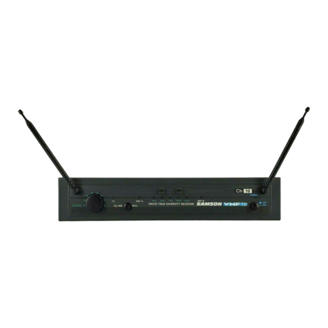
Samson Concert99 User manual

Samson

Samson Concert99 User manual

Samson Airline 77 User manual

Samson

Samson Airline 77 User manual

Samson Stage 212 User manual

Samson

Samson Stage 212 User manual

Samson UHF 801 User manual

Samson

Samson UHF 801 User manual

Samson AirLine User manual

Samson

Samson AirLine User manual

Samson EXPEDITION XP40iw User manual

Samson

Samson EXPEDITION XP40iw User manual

Samson CONCERT 88X User manual

Samson

Samson CONCERT 88X User manual

Samson UHF Series One User manual

Samson

Samson UHF Series One User manual

Samson AirLine 88 Series User manual

Samson

Samson AirLine 88 Series User manual

Samson VHF Series User manual

Samson

Samson VHF Series User manual

Samson AIRLINE CR77 User manual

Samson

Samson AIRLINE CR77 User manual

Samson CT7 User manual

Samson

Samson CT7 User manual

Samson Concert 88 User manual

Samson

Samson Concert 88 User manual

Samson AirLine SYNTH AR300 User manual

Samson

Samson AirLine SYNTH AR300 User manual

Samson CONCERT 99 User manual

Samson

Samson CONCERT 99 User manual

Samson Concert 99 SWC99HQ8-D User manual

Samson

Samson Concert 99 SWC99HQ8-D User manual

Samson Airline 77 User manual

Samson

Samson Airline 77 User manual

Samson Concert88 User manual

Samson

Samson Concert88 User manual

Samson CONCERT SERIES IV User manual

Samson

Samson CONCERT SERIES IV User manual

Samson STAGE 266 HT6 User manual

Samson

Samson STAGE 266 HT6 User manual
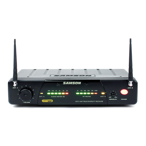
Samson SynthSeven User manual

Samson

Samson SynthSeven User manual

Samson Concert 288 User manual

Samson

Samson Concert 288 User manual

Samson Airline 88 User manual

Samson

Samson Airline 88 User manual

Samson Airline 77 User manual

Samson

Samson Airline 77 User manual

Popular Microphone System manuals by other brands

Studiomaster BR 28 SERIES instruction manual

Studiomaster

Studiomaster BR 28 SERIES instruction manual

Fiber-Span AC3101-BTR-4 Installation guide and user's manual

Fiber-Span

Fiber-Span AC3101-BTR-4 Installation guide and user's manual

AKG SR 45 User instructions

AKG

AKG SR 45 User instructions

Boston gear ORC-S Series Installation & operation instructions

Boston gear

Boston gear ORC-S Series Installation & operation instructions

DIGITECH Audio AM-4114 user manual

DIGITECH Audio

DIGITECH Audio AM-4114 user manual

RELACART MS1 quick start guide

RELACART

RELACART MS1 quick start guide

Galaxy Audio Galaxy Trek GT-INST-6 user manual

Galaxy Audio

Galaxy Audio Galaxy Trek GT-INST-6 user manual

RCS UWR-701 F operating instructions

RCS

RCS UWR-701 F operating instructions

Malone Duett Pro V1 manual

Malone

Malone Duett Pro V1 manual

Azden WHX-PRO instruction manual

Azden

Azden WHX-PRO instruction manual

Shure Performance Gear user guide

Shure

Shure Performance Gear user guide

Saramonic UwMic9 user manual

Saramonic

Saramonic UwMic9 user manual

Shure ULX-D manual&nbsp;

Shure

Shure ULX-D manual&nbsp;

Velvet Drive 71C Service manual

Velvet Drive

Velvet Drive 71C Service manual

Shure T series user guide

Shure

Shure T series user guide

Huawei OptiX RTN 950 Quick installation guide

Huawei

Huawei OptiX RTN 950 Quick installation guide

Sony Digital Wireless Generation 3 manual

Sony

Sony Digital Wireless Generation 3 manual

Clockaudio CUI-2 user manual

Clockaudio

Clockaudio CUI-2 user manual

manuals.online logo
manuals.online logoBrands
  • About & Mission
  • Contact us
  • Privacy Policy
  • Terms and Conditions

Copyright 2025 Manuals.Online. All Rights Reserved.