10 EB 8389S EN
Description
1.2.1 Reference tests
The monitoring of friction, supply pressure,
leakage (pneumatics and to the atmosphere),
zero point and actuator springs requires ad-
ditional reference tests for 'Drive signal dia-
gram steady-state' (test d1) and 'Drive signal
diagram hysteresis' (test d2). See u Section
4.1 and section 4.2.
NOTICE
−The valve moves through its work-
ing range during the reference test.
−The reference test cannot be per-
formed if the positioner has been
initialized in the substitute calibra-
tion (SUB) mode.
Right-click 'Start reference test' in the Diag-
nosis folder and select ‘Execute’ to start the
recording of reference data. tESt and d1 or
d2 appear in alternating sequence on the
positioner display.
Note:
−Right-click 'Stop reference test'
and select ‘Execute’ to can-
cel the reference test.
−The positioner records the ref-
erence data automatically af-
ter initialization if 'Initialization
with reference test' is set to Yes.
−A new reference test causes the
results of existing reference tests
to be overwritten and the di-
agnostic data to be deleted.
−If the reference data could not be
recorded correctly or are incom-
plete, Code 48 - h1 is generated
−in the positioner. If the 'Initializa-
tion with reference test' parameter
is activated, an incorrect reference
test is also indicated in Code 81.
−The positioner can still perform
its control task properly even if
the reference test was not record-
ed correctly or is incomplete.
−Data from the rst reference test
are used as the reference if no ref-
erence data are saved in the posi-
tioner on starting the tests for 'Drive
signal diagram steady-state' or
'Drive signal diagram hysteresis'
Diagnostics
−Start reference test (Code 48 - d7)
or
Start-up
−Initialization with reference test (Code 48 - h0):
Yes, [No]
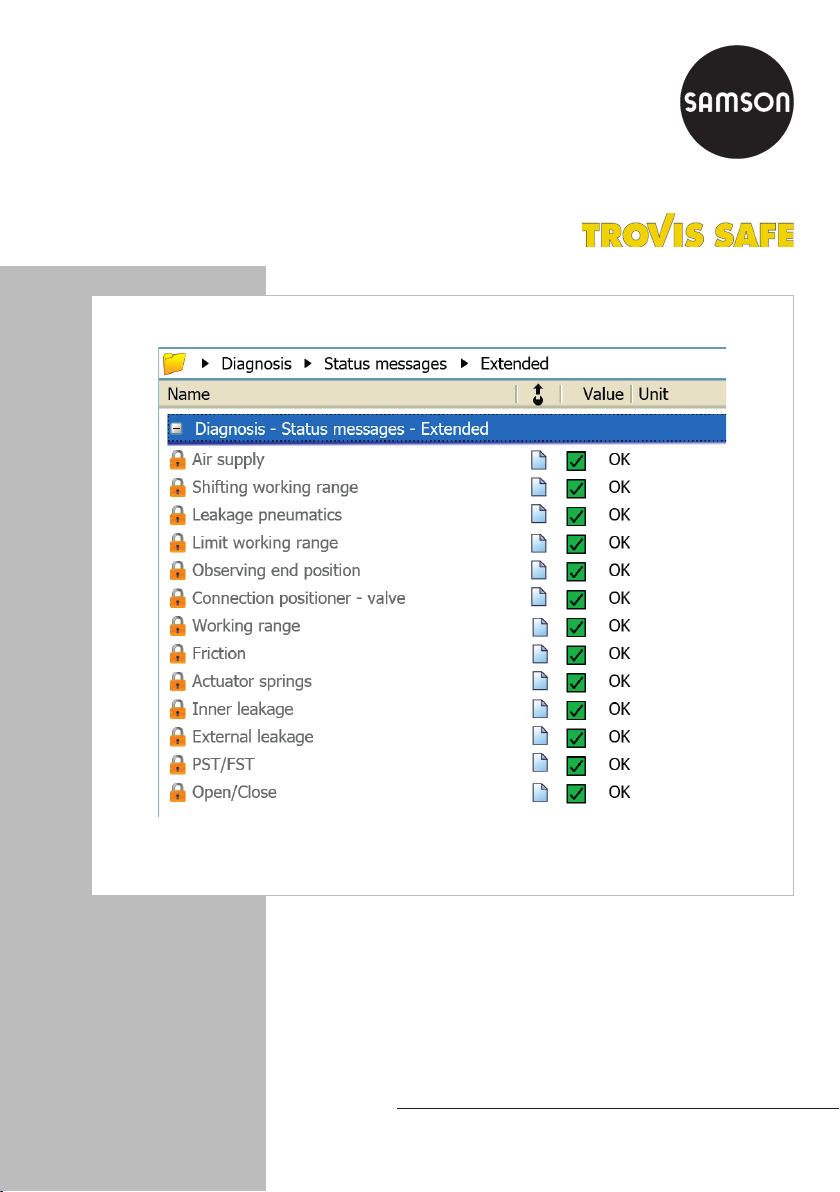
1.3 Diagnostic functions
There are two main groups of diagnostic
functions available: Statistical information
(in-service monitoring) and Tests (out-of-ser-
vice diagnostics).
1. Statistical information (in-service moni-
toring)
Data are compiled, saved and analyzed
by the positioner while the process is
running without disrupting the process.
The positioner follows the set point to po-
sition the valve. A classied status alarm
or fault alarm is generated if the posi-
tioner detects an event.