manuals.online logo
Brands
  1. Home
  2. •
  3. Brands
  4. •
  5. Elenco Electronics
  6. •
  7. Test Equipment
  8. •
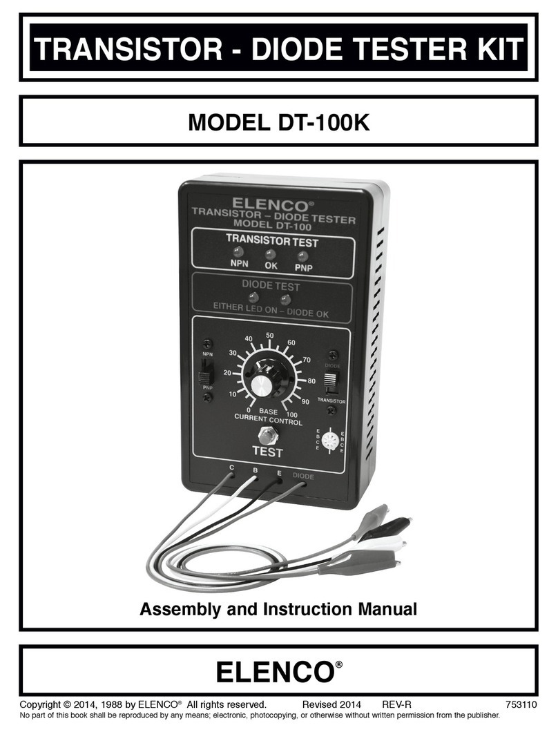
  9. Elenco Electronics DT-100 User manual

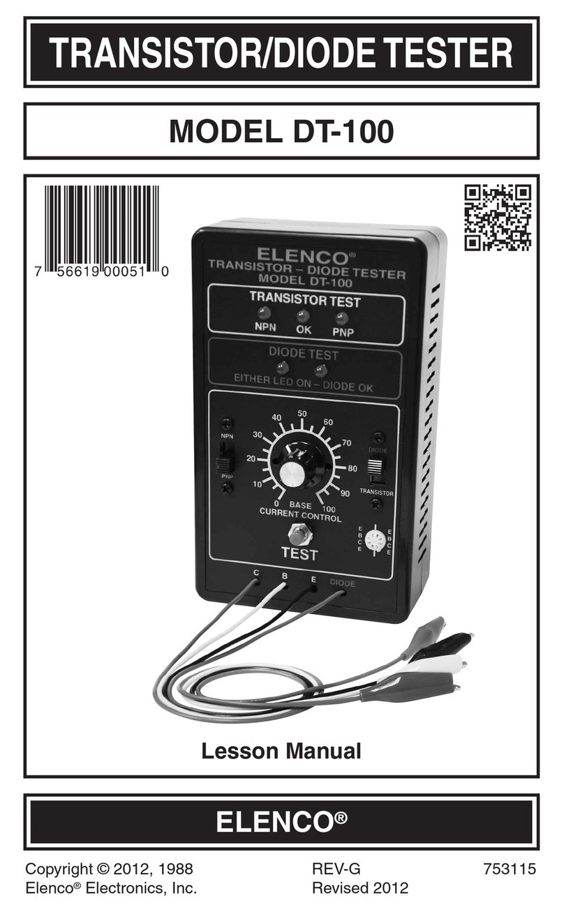
Elenco Electronics DT-100 User manual

TRANSISTOR/DIODE TESTER
MODEL DT-100
Lesson Manual
Elenco Electronics, Inc.
Copyright © 1988 Elenco Electronics, Inc. REV-D 753115
Revised 2001
Elenco Electronics, Inc.
150 W. Carpenter Avenue
Wheeling, IL 60090
(847) 541-3800
http://www.elenco.com
e-mail: elenco@elenco.com
TWO YEAR WARRANTY
All Elenco models are guaranteed for two full years
on all parts and service. For the first 3 months,
your power supply is covered at absolutely no
charge. For the remaining 21 months, a nominal
service charge is required to cover shipping and
handling.
When returning merchandise for repair,
please include proof of purchase, a brief letter
of explanation of problem, and sufficient
packing material. Before returning any
merchandise please call our service
department at (847) 541-3800 to obtain a
return authorization number (RMA).
-1- -6-
FEATURES
Diode Mode:
1. Checks all types of diodes - germanium, silicon, power, light
emitting (LEDs), and zener.
2. Indicates the cathode or anode leads of the diode.
3. Operates in circuit with resistors as low as 5kW.
Transistor Mode:
1. Checks all types of transistors - germanium, silicon, power, RF,
audio, switching, and FETs.
2. Identifies NPN and PNP types, PN or NP junctions.
3. High gain circuit, can test transistors in circuits with base or
collector resistors as low as 100W.
4. Measures relative beta of two transistors.
SCHEMATIC DIAGRAM
-5-
DT-100 PARTS LIST
Resistors 5% 1/4W
Qty. Symbol Value Color Code Part #
1 R14 100Wbrown-black-brown-gold 131000
2 R5, R6 220Wred-red-brown-gold 132200
2 R1, R10 330Worange-orange-brown-gold 133300
1 R13 1kWbrown-black-red-gold 141000
1 R7 5.6kWgreen-blue-red-gold 145600
1 R12 10kWbrown-black-orange-gold 151000
1 R8 18kWbrown-gray-orange-gold 151800
2 R2, R3 33kWorange-orange-orange-gold 153300
1 R9 47kWyellow-violet-orange-gold 154700
1 R11 100kWbrown-black-yellow-gold 161000
1 R4 330kWorange-orange-yellow-gold 163300
1 R15 100kWVariable Potentiometer 192611
Capacitors
Qty. Symbol Value Description Part #
1 C6 0.001mF (102) Discap 231036
3 C2, C3, C5 0.01mF (103) Discap 241031
2 C1, C4 10mF Lytic 271045
Semiconductors
Qty. Symbol Value Description Part #
1 D1 1N4001 Diode 314001
1 Q5 MPS A70 Transistor 320070
4 Q1 - Q4 2N3904 Transistor 323904
1 IC1 555 Integrated Circuit 330555
5 L1 - L5 Light Emitting Diode 350002
Miscellaneous
Qty. Description Part #
1 PC Board 511100
1 Switch Push Button 540001
2 Switch DPDT 541111
1 Battery Snap 590098
1 Panel Front 614100
1 Knob 622009
1 Case 623240
5 Spacer LED 624111
4 Screw 4-40 x 1/4” 641430
1 Nut Pot 7mm 644101
1 Flat Washer 645101
4 Nut 4-40 644400
Qty. Description Part #
1 Lockwasher 5/16” Int. 646101
1 Socket 8-Pin IC 664008
1 Transistor Socket 664500
1 Clip Black 680001
1 Clip Red 680002
1 Clip Green 680003
1 Clip Yellow 680004
1 Wire Black 20 ga. 813110
1 Wire Red 20 ga. 813210
1 Wire Yellow 20 ga. 813410
1 Wire Green 20 ga. 813510
1 Wire Blue Solid 22 ga. 814620
-2-
OPERATING INSTRUCTIONS
The DT-100 is a dynamic transistor and diode tester. It features in-
circuit testing and polarity indicators for both transistors and
diodes. To activate the DT-100, remove the four front mounting
screws and install a fresh 9V battery.
Diode Testing
1. Place the switch in the diode position.
2. Connect the diode to the red and black leads.
3.
Push in the test switch. One diode LED should blink and identify
whether the cathode or anode is connected to the diode (red) lead.
4. If both LED lamps blink, then the diode is shorted.
5. If neither LED lamps light, then the diode is open.
Transistor Mode:
The DT-100 can measure transistors in or out of circuit. It will
identify NPN or PNP by a simple adjustment.
Transistor Testing - Out of Circuit
1. Place the switch in the transistor position.
2. Place the transistor in the socket or attach it to the C, B, and E
leads.
3. Push in the test button. Adjust the base current control so that
the OK LED lights up. This indicates a good transistor.
4. If the OK lamp doesn’t light, adjust the base current control so
that either the NP or PN LED lights up. This happens at the
minimum or maximum position of the control setting. This will
indicate transistor type. Place the switch to the NPN position if
the NP lamp lights up, or place the switch to the PNP position if
the PN lamp is lit.
5. If no lamps light up, then the transistor is open or we have not
identified the base lead. Repeat assuming another lead at the
base.
-3-
6. When the transistor is shown to be OK, the base current control
gives an indication of transistor beta. The lower the setting
relative to another transistor, the higher the beta. Lamps NP
and PN measure base current. Higher base current results in a
brighter LED. It also indicates if current is entering or leaving
the base, thus, NP or PN respectively will light.
Transistor Testing - In Circuit
The DT-100 will test transistors in circuit, provided the base biasing
resistance is greater than 100W. Simply follow the previous
procedure for testing out of circuit transistors. Do not apply power
to the circuit of the transistor or diode under test. The DT-100 will
supply the necessary power.
CHECKING OUT YOUR TRANSISTOR/DIODE TESTER
The following is a simple procedure for testing your DT-100.
Diode Operation:
1. Place the switch in the diode position. Short the black and red
leads together and push in the test button. The diode test LEDs
should alternately go on at about a 1Hz rate.
2.
Connect the red and black leads to any good diode. Only one LED
should flash, identifying the red lead connection (anode or
cathode). Reversing the leads should cause the other LED to flash.
Transistor Operation:
1. Place the switch in the transistor position. Short the yellow (B)
and black (E) leads together. Press the test button. Vary the
base current control. The NP lamp should light with the switch
in the NPN position and the PN lamp when the switch is in the
PNP position.
2. Place a known good transistor in the test socket with the Emitter
in E, Base in B and Collector in C pins. Be sure none of the
leads are shorting. Vary the base current control. The OK LED
should light up. Note that on the NPN transistor, the NP lamp
also will glow very slightly. This indicates the base current, and
thus lower intensity. The base current control should be
adjusted for the lowest setting with the OK lamp glowing.
-4-
THEORY OF OPERATION
Note the schematic diagram on page 6. The test transistor in this
circuit is an NPN. Adjusting the variable resistor will cause the
NPN LED to light up indicating that the base current is flowing. The
output of the test transistor is fed to amplifiers Q2 and Q3. The
output of Q2 is feedback in phase to the base of the test transistor
causing the circuit to oscillate. Part of the oscillations are fed to a
power rectifier, Q5, which switches on the OK LED indicator.
The design configuration is such that in-circuit transistors can be
measured, provided that the base and collector resistors are
greater than 100W.
When measuring PNP transistors, the power supplied to the test
transistor is reversed via the NPN/PNP switch. Therefore, the PN
LED will light up.
Varying the base current control will reduce the base current. The
lower the base current, the higher the gain of the transistor under
test. Comparative tests of two transistors’ gain (beta), can be
made by observing the dial setting or the intensity of the base LED
diode. The lower the setting with the PN LED lit, the higher the
beta of that transistor.
On diode operation, power is applied to IC1. This causes the
circuit to oscillate at about a 1Hz rate. Placing a diode in series
with the LED indicators will cause a current to flow, depending on
the direction of the diode. Thus, the red test lead will identify the
cathode or anode of the diode via the LED readout. Transistor Q4
reverses the current flow in this circuit.
All types of diodes may be tested: Silicon, germanium, LEDs or
zeners over 6 volts. Zener diodes under 6V causes the second
LED to glow at lower intensity, indicating that zener breakdown has
occurred.
Other Elenco Electronics Test Equipment manuals

Elenco Electronics XK-150 User manual

Elenco Electronics

Elenco Electronics XK-150 User manual

Elenco Electronics S-1325 User manual

Elenco Electronics

Elenco Electronics S-1325 User manual

Elenco Electronics DT-100K User guide

Elenco Electronics

Elenco Electronics DT-100K User guide

Elenco Electronics MO-1252 User manual

Elenco Electronics

Elenco Electronics MO-1252 User manual

Elenco Electronics DT-100 User manual

Elenco Electronics

Elenco Electronics DT-100 User manual

Elenco Electronics RS-400/K-37 User guide

Elenco Electronics

Elenco Electronics RS-400/K-37 User guide

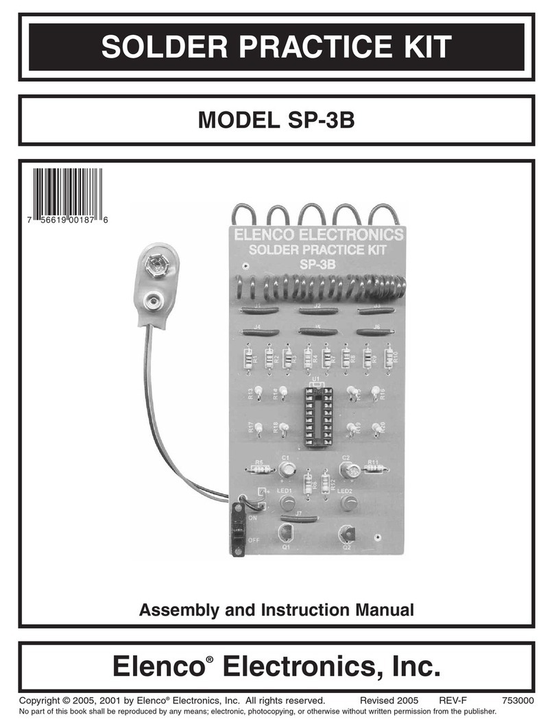
Elenco Electronics SP-3B User guide

Elenco Electronics

Elenco Electronics SP-3B User guide

Elenco Electronics SG-9000 User manual

Elenco Electronics

Elenco Electronics SG-9000 User manual

Elenco Electronics XK-700TK Installation guide

Elenco Electronics

Elenco Electronics XK-700TK Installation guide

Elenco Electronics S-3000 User manual

Elenco Electronics

Elenco Electronics S-3000 User manual

Elenco Electronics ST-751 User manual

Elenco Electronics

Elenco Electronics ST-751 User manual

Elenco Electronics AK-700 User guide

Elenco Electronics

Elenco Electronics AK-700 User guide

Elenco Electronics RS-500 User manual

Elenco Electronics

Elenco Electronics RS-500 User manual

Elenco Electronics MO-1251 User manual

Elenco Electronics

Elenco Electronics MO-1251 User manual

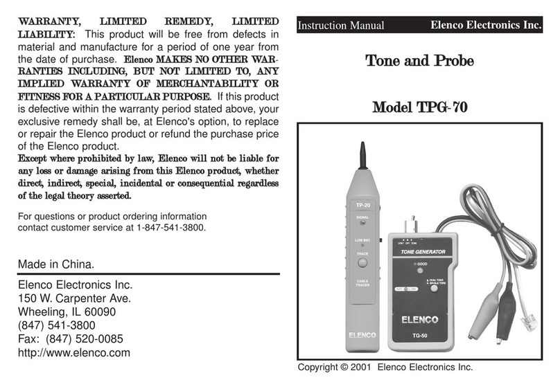
Elenco Electronics TPG-70 User manual

Elenco Electronics

Elenco Electronics TPG-70 User manual

Popular Test Equipment manuals by other brands

Agilent Technologies 5DX II Series installation guide

Agilent Technologies

Agilent Technologies 5DX II Series installation guide

Fluke 725Ex Calibration manual

Fluke

Fluke 725Ex Calibration manual

Tektronix TU-7 instruction manual

Tektronix

Tektronix TU-7 instruction manual

Teledyne Lecroy T3DSO3000 user manual

Teledyne Lecroy

Teledyne Lecroy T3DSO3000 user manual

Spectracom Pendulum PathAlign-R 2200 user manual

Spectracom

Spectracom Pendulum PathAlign-R 2200 user manual

Multimetrix ERT 200 User manua

Multimetrix

Multimetrix ERT 200 User manua

Tsuruga 8525 instruction manual

Tsuruga

Tsuruga 8525 instruction manual

Keysight 8497K Operating and service manual

Keysight

Keysight 8497K Operating and service manual

Dawson DET 301 user manual

Dawson

Dawson DET 301 user manual

Gossen MetraWatt METRAHit 28C light operating instructions

Gossen MetraWatt

Gossen MetraWatt METRAHit 28C light operating instructions

Megger TTR25 instruction manual

Megger

Megger TTR25 instruction manual

Compliance West HT-2800P instruction manual

Compliance West

Compliance West HT-2800P instruction manual

Velleman HPS140i user manual

Velleman

Velleman HPS140i user manual

Rigol MSQ7054 user guide

Rigol

Rigol MSQ7054 user guide

PeakTech 2530 Operation manual

PeakTech

PeakTech 2530 Operation manual

Agilent Technologies InfiniiVision 4000 X-Series user guide

Agilent Technologies

Agilent Technologies InfiniiVision 4000 X-Series user guide

AlcoMate premium AL-7000 user manual

AlcoMate

AlcoMate premium AL-7000 user manual

Bosch BAT 131 Original instructions

Bosch

Bosch BAT 131 Original instructions

manuals.online logo
manuals.online logoBrands
  • About & Mission
  • Contact us
  • Privacy Policy
  • Terms and Conditions

Copyright 2025 Manuals.Online. All Rights Reserved.