All-sun EM1230 User manual
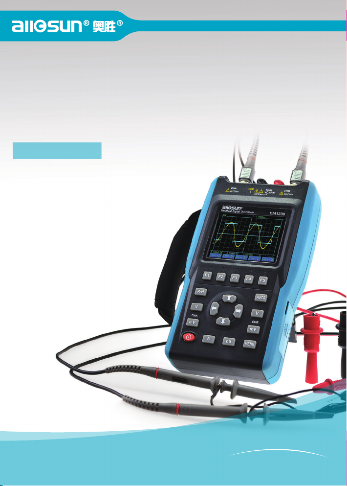
2 in 1 Handheld Color Screen Oscilloscope
Oscilloscope Function &
Digital Multimeter Function
HANDHELD DIGITAL OSCILLOSCOPE
手持式彩屏示波表
Users Manual
Model: EM1230
Y
o
u
r
P
r
o
f
e
s
s
i
o
n
a
l
C
h
o
i
c
e
!


2
Brief introduction...................................................................................................3
General Safety Requirement ..................................................................................4
Package Checklist ..................................................................................................5
The following items are included in this Instrument..............................................5
Chapter I Recognizing this product.......................................................................6
1. Product Description....................................................................................6
1.1 Front Pane ............................................................................................6
1.2 Measurement port.................................................................................7
2. Panel keyboard and display interface.........................................................8
2.1 Panel function keys .............................................................................8
2.2 Display Interface .................................................................................9
3. The main measurement function and menu structure ..............................10
3.1 The main measurement function .......................................................10
3.2 Menu structure ..................................................................................10
Chapter II Use instrument ...................................................................................19
1. Oscilloscope.............................................................................................19
1.1 Test connection ..................................................................................19
1.2 Oscilloscopemeasurement applications.............................................20
2. DMM........................................................................................................24
2.1 Test the connection ............................................................................24
2.2 Multimeter..........................................................................................24
Chapter Interface and Software......................................................................26
Chapter Maintenance and repair ....................................................................28
Chapter Warranty...........................................................................................30
Chapter Technical Specifications...................................................................31
EM1230 Handheld Digital Oscilloscope User ,s Manual

3
Brief introduction
EM1230 is a 25MHz digital storage oscilloscope,6000 words True RMS
Digital Multimeter functions integrated multifunctional handheld instrument, ideal for field use.
The main function
2-channel ,25MHz digital storage oscilloscope
True 6000 words RMS digital multimeter
Features
100MSa / s real-time sampling rate, 25MHz real-time bandwidth
Automatic tracking measurement: automatic tracking based on external input signal to
adjust the vertical amplitude \ horizontal time base and trigger stalls, without human
intervention
Large dynamic measurement range: no extended probe leads directly measure range from
10mV/div to 500V/div
Screen can display 4 measurement parameters the user can choose RMS, peak, average,
frequency, period, in 22 kinds of parameters as needed, etc.
Two kinds of cursor measurement mode selection
320 * 240 dot TFT LCD,
Built-in battery, AC and DC
Recorder --- continuous track record up to 12 hours of event
Standard USB interface, through the PC software can easily communicate with a computer
for data analysis and test results archive
UserEM1230 Handheld Digital Oscilloscope ,s Manual

4
General Safety Requirement
Carefully read the following safety information to avoid personal injury and the damages of this
product or any other connected products. To avoid all possible dangers, this product only should
be used in stated range.
Only an eligible technologist has the maintenance right
Avoiding fire or personal injury
Use the proper power adapter. Use only the power supply or sanctified power adapter.
Connect or disconnect correctly. Do not connect or disconnect probes and test leads at
will when they are connected to the power.
Notice all terminals’ ratings. To avoid electrical shock or fire, notice carefully all ratings
and signs of this product. And read carefully the users manual to get more information about the
ratings before connect to this product.
Do not operate the meter without its cover. Do not use the meter if its cover or panel
has been unloaded.
Avoid touching bare circuit. Do not touch the bare nodes or parts of the product with
power on.
Do not operate with dubious troubles. If you have dubious troubles on the product, let
an eligible technologist have a check.
Do not operate under a humid environment.
Do not operate under an explosive environment.
Keep the meter clean and dry.
Safety terms and signs
This manual is possible to show following terms
Warning. The word Warning indicates that the condition or the operation maybe
cause personal injury.
Carefully. The word Carefully indicates that the condition or the operation maybe
cause the damages of this product or other properties
EM1230 Handheld Digital Oscilloscope User ,s Manual

UserEM1230 Handheld Digital Oscilloscope ,s Manual
5
Package Checklist
The following items are included in this Instrument
No. Description Quantity Remark
1 Handheld Oscilloscope 1
2 Li Battery Pack 1 installed
3 AC/DC Power Adapter 1
4 Oscilloscope Probes 1
5 Multimeter Test Leads 2 (red, black)
6
7
USB Cable 1
8
Current Probe 1 Optional
Users Manual 1

CHBTRIGCHA
CHA CHB
33
EM1230
F1 F2 F3 F4 F5
R/H
V V
S nS
mV mV
AUTO
MENU
6
Chapter I.Recognizing this product
EM1230 Handheld Digital Oscilloscope User ,s Manual
1 Product Description
1.1 Front Pane
The Product is a handheld portable products, AC and DC power supply, 3.7V lithium battery
inside the instrument; external AC-DC adapter with 220/5V can provide external power and
charge the lithium battery inside the instrument instrument
Side port
AC-DC adapter
Power
j
ack and USB
320×240 TFT
LCD screen
Measurement
port
Panel and
function keys
Handle

UserEM1230 Handheld Digital Oscilloscope ,s Manual
CHBTRIGCHA
CHA CHB
33
EM1230
F1 F2 F3 F4 F5
R/H
V V
S nS
mV mV
AUTO
MENU
7
1.2 Measurement port
CHA CHB External signal input test port, CHA and CHB either as single-channel
oscilloscope can also be used as a dual-channel oscilloscope in the oscilloscope mode.
COM Oscilloscope and multimeter measurements common ground port
TRIG:
1 Oscilloscope mode Used in SCOPE mode to trigger (or start) acquisitions from an external
source
2Multimeter mode DC voltage \ AC voltage \ Resistance \ Continuity \ Diode \ capacitance \
current measurement input ports
Note:
1Note that each port safety limit, do not exceed the maximum test range
2The multimeter testing current mode, you must use the current probe
3Note that proper grounding
(Incorrect Grounding) (Correct Grounding)
A ground loop can be created when you use two ground leads connected to different ground
potentials. This can cause excessive current through the grounding leads
EM1230 Handheld Digital Oscilloscope User ,s Manual
8
2Panel keyboard and display interface
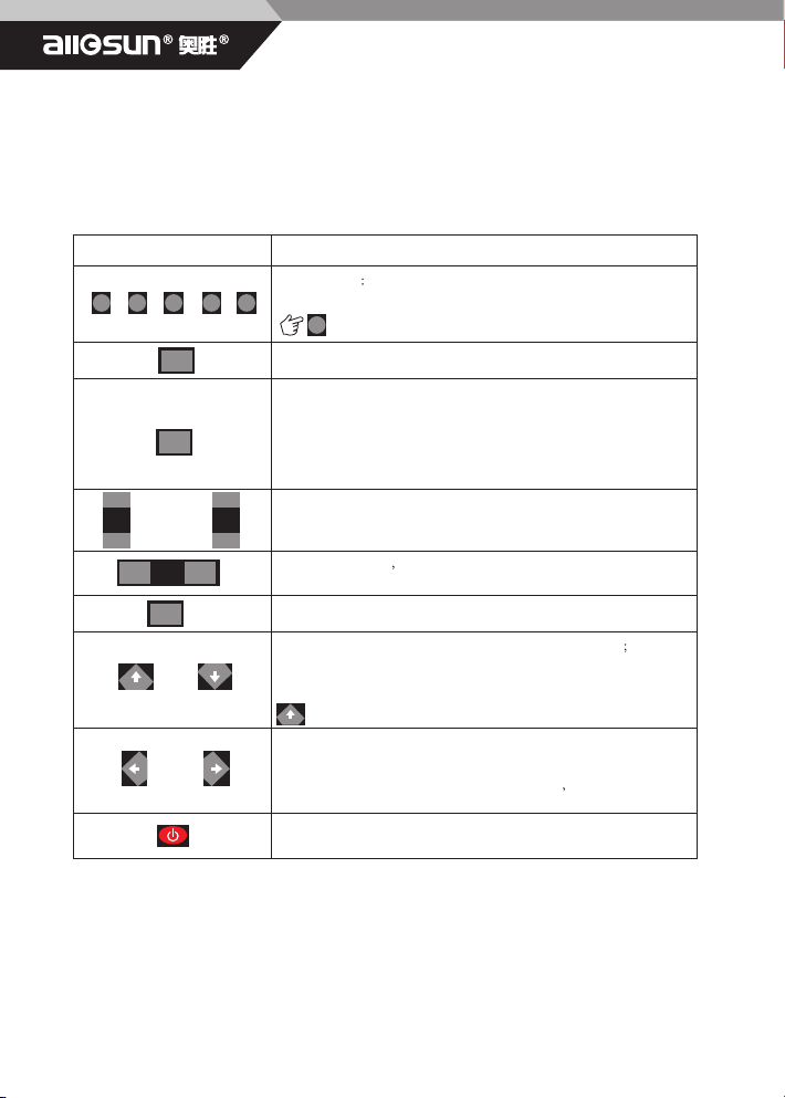
2.1 Panel function keys
key Description
Function keys The function assigned to each key is indicated by the
Function Key Label displayed above the key on the bottom display
In most of the menu to return to the previous menu
Run \ hold, lock screen
Sets automatic ranging on and off (toggle).
When on, the top right display shows AUTO. When this function is set
on, it searches for the best range and time base settings and once found it
tracks the signal. When this function is off, you should manually control
ranging.
In oscilloscope mode, use the key to adjust the CHA \ CHB
channel vertical amplitude sensitivity
Oscilloscope mode Press the key, making the timebase adjustment
effectively
Menu softkey
Move up and down a waveform \ trigger level \ voltage cursor
Manually change the sensitivity level of the base, multimeter voltage \
resistance \ capacitors \ Current gear change;
Can also be used as a return to the previous menu key
Moves a waveform or Time cursor right and left;
Ranges amplitude up and dow or Change the trigger edge;
Move around and select the current coefficient bits Menu selection
Turns the power on and off (toggle). When you turn the power on,
previous settings are activated.
F1
F1
F2 F3 F4 F5
R/H
S nS
AUTO
MENU
V
mV
CHA
V
mV
CHB

UserEM1230 Handheld Digital Oscilloscope ,s Manual
9
2.2 Display Interface
2.2.1 Oscilloscope
Trigger Mode Time Zero
Battery indicator
Parameter display
Waveform display
Trigger level
CHA zero level
CHB zero level
Vertical / horizontal range Frequency Counter
Menu Module
2.2.2 DMM
State display area
Data display area
The current gear,
measuring state
Measurement items
Indicate trigger slope
(rising or falling).
External power Run \ Hold Communication status
EM1230 Handheld Digital Oscilloscope User ,s Manual
MENU
MENU
F1
F1
F2
F2
V
mV
CHA
V
mV
CHB
10
3 The main measurement function and menu structure
3.1 The main measurement function
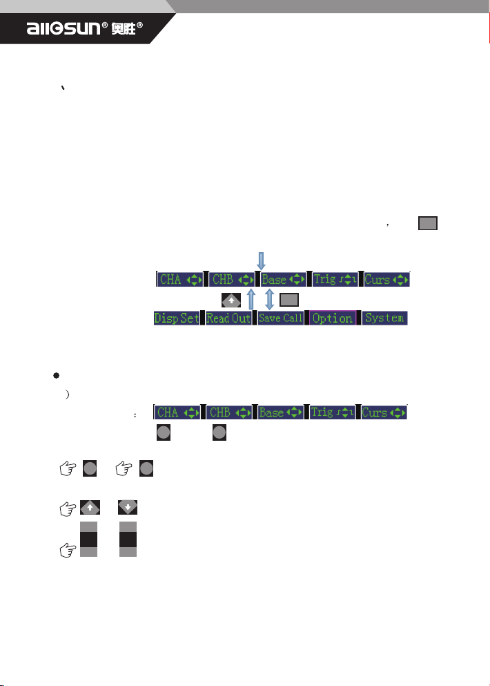
3.2 Menu structure
The menu has two major main menu module, divided into two screen display Press key
switch, each screen 5 menu module
Power On
The main menu 1
The main menu 2
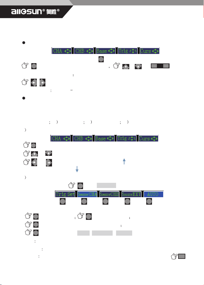
3.2.1 Oscilloscope menu operation
The vertical range
1Move up and down channel A \ B waveform and adjust the vertical range
The main menu
or Effective corresponding channel A, or channel B.
or Move up and down waveforms.
or Adjust the vertical range
The instrument has the oscilloscope, multimeter measurement function, wherein, the
oscilloscope and multimeter are two independent measuring function.
UserEM1230 Handheld Digital Oscilloscope ,s Manual
F1 F2
F2
F3
F3
F4
F4
F5
F5
F1 F2 F3 F4 F5
F1 F1F2
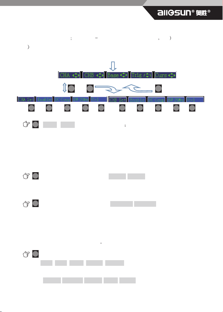
11
Adjust the vertical range 10mV/div 500V/div(No probe attenuation 1:1
2 Channel A\B other settings
Power On
Enable / disable the channel CHA / CHB
The instrument can display the input A or B input signal waveform in dual-channel oscilloscope
mode, the input A and input B signals simultaneously displayed.if the user wants to measure
individual signals, selectable single-channel oscilloscope mode, simply connect the input A that
to the input B closed; Conversely, if the user wants to simultaneously measure two
signals ,directly using dual-channel oscilloscope mode while connected to input A, input B.
Select CHA / CHB signal coupling, DC coup/AC coup
DC Coupling allows you to measure and display both the DC and AC components of a signal.
AC Coupling blocks the DC component and passes the AC component only.
Select the CHA/CHB bandwidthlimitBW25MHz/BW10KHz
There are cases where you may want to filter out noises in order to see a better signal. This can
be especially true when ignition noise is present. The instrument provides a noise filter for each
input channel which reduces the bandwidth from its normal 25MHz to10KHz. You can enable or
disable CH A Filter or CH B Filter using the INSTRUMENT SETUP menu. When enabled, the
FILTER indicator appears on the screen.
Select the CHA/CHB voltage probe attenuation coefficient
V:×1/ V:×10/ V:×100/ V:×1000/ V:×10000
Or select the CHA/CHB current probe conversion coefficient
1mA/mV;10mA/mV;0.1A/mV;1A/mV;10A/mV
You can according to the probe type CHA or CHB (voltage probe, current probe) to select its
EM1230 Handheld Digital Oscilloscope User ,s Manual
12
corresponding attenuation factor or conversion factor
Time base range
Main Menu
Effective timing adjustment function or Horizontal
compression expansion wave
Moves the waveform in the horizontal direction
Time base range 10ns/div 2h/div
Trigger
TRIGGER is a set of conditions that determine whether and when acquisitions start. The
following will determine the trigger conditions
a) Trigger Edge b Trigger Level c Trigger Source d Trigger mode
1Changing the trigger edge and trigger level
Main Menu
Effective trigger function
or Move up and down the trigger level
or Changing the trigger edge ,If you select , trigger occurs at a rising(positive)
edge of the signal. If you select , trigger occurs at a falling(negative) edge of the signal.
2Change the trigger mode and select the trigger source
Main Menu to continue Go to Trigger Set menu
Select CHA trigger Select CHB trigger
Select the external signal as the trigger source
Select trigger mode: AUTO \ NORMAL \ SINGLE
AUTO The instrument always performs acquisitions, i.e., it always displays the signals on the input.
NORMAL If NORMAL is selected, a trigger is always needed to start an acquisition
SINGLESINGLE allows you to perform single acquisition to snap events that occur only once. is
used to start a next single acquisition.
F3
F3 S nS
F4
F4
F1 F2
F2
F3
F3
F4
F4
F5
F5
R/H
UserEM1230 Handheld Digital Oscilloscope ,s Manual
13
Return to the previous menu
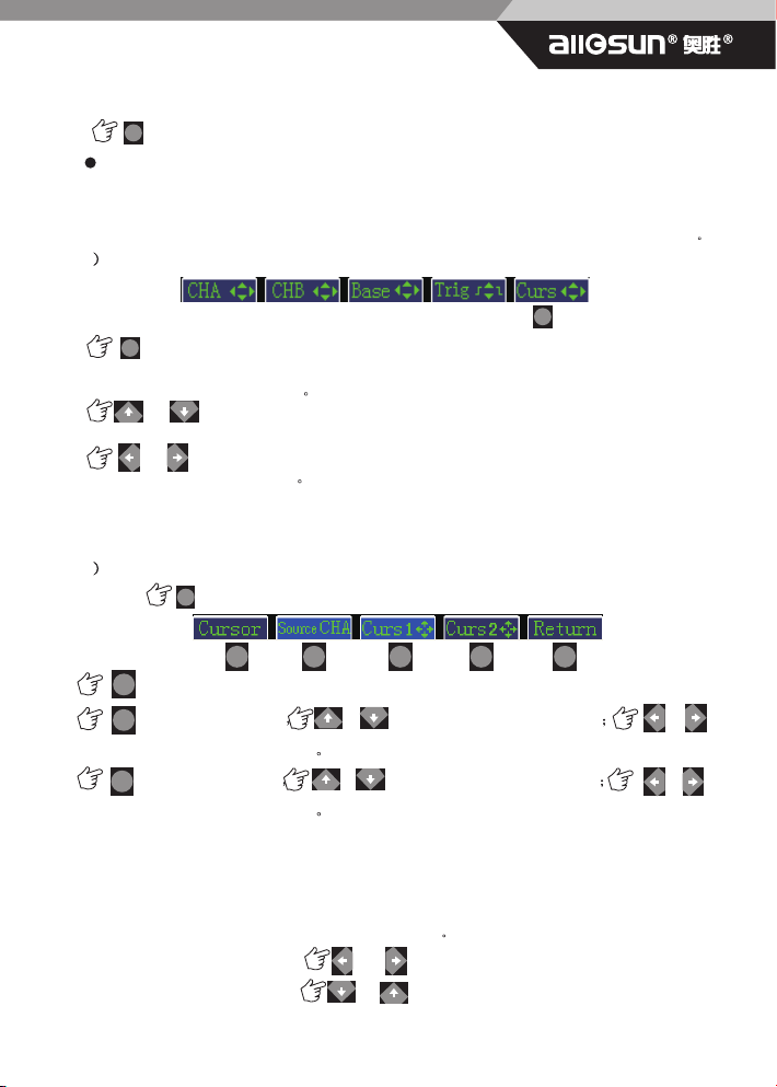
Cursor
A cursor is a vertical line or a horizontal line placed over the displayed waveform to measure
values at certain points.The instrument can measure signal details by using Cursors ,Single
cursor mode is suitable for absolute measurements, dual cursor suitable relative measurement
1 Single cursor measurement mode
Main Menu
Effective single cursor mode, a red horizontal line and a red vertical line appears on
the screen, representing the VOLTS and TIME cursors for measuring relative to the reference
(amplitude and time) offset value
or Move the cursor up and down the VOLTS cursor ; higher than the zero level
line is positive, below the zero level line is negative.
or To move the TIME cursor left and right; negative at a time reference on the left,
at the right time basis is positive
Note: a single cursor mode is effective for channel A, channel B can be read out at the
same time, the double channel value
2 Double cursor measurement model
Continue Into double cursor measurement mode
Effective CHA or CHB cursor
The cursor 1 effective or Move up and down VOLTS cursor or to
move the TIME cursor left and right
The cursor2 effective or Move up and down VOLTS cursor or to
move the TIME cursor left and right
In this mode, the two cursor is only valid for the current channel, two cursor each channel
for the same type of cursor, or VOLTS cursor , or TIME cursor. Each cursor to measure the
relative value of the deviation between the reference and the two cursors relative
Two cursor mode can be converted to each other
In the VOLTS cursor mode, or converted to TIME cursor;
In the TIME cursor mode, or converted to VOLTS cursor.
F5
F1
F5
F5
F1 F2
F2
F3
F3
F4
F4
F5

F1
EM1230 Handheld Digital Oscilloscope User ,s Manual
14
or Return to the previous menu
Display Set
Main Menu
Display Set menu
1Persist
When a new waveform display, before the waveform on the screen does not disappear
immediately, but continue for some time, namely persistence time, by setting the persistence
time waveform display allows more continuous, and then get a similar analog oscilloscope
display
Select the persist time 1Second\2SSecond\5SSecond\Infinite
or Return to the previous menu
2Average
The average acquisition mode can reduce the display signal of random and unrelated noise,
sampling value in real-time sampling mode, and then repeatedly sampled waveform average
calculation
In the Display Set menu
Select the average time 4 times \ 164 times \ 324 times \ 64times
F5
F1
F1 F2
F2
F3 F4 F5
F1
F1
F2
F2
F3
F3
F3
F4
F4
F5
F1 F2 F3 F4 F5
F5
F2 F3 F4 F5

UserEM1230 Handheld Digital Oscilloscope ,s Manual
15
or Return to the previous menu
3 Reference Waveform
The user can be real-time measured waveform as the standard waveform storage, so the next
measurement comparison
In the Display Set menu
Turns the CHA Reference Waveform on and off (toggle).
Turns the CHB Reference Waveform on and off (toggle)
Storage Reference Waveform
Recall Reference Waveform
or Return to the previous menu
Read Out
Main Menu
Set out parameter types 1 to 4
Select the active channel parameter readout(CHA\CHB) or Select the
type of read-out
Open \ close Read out on screen display
Measurement results can be displayed as numeric values (referred to as readings) and waveform.The types of
readings depend on the test taking place:Maximum, minimum, peak, average, RMS and other 21 kinds of
parameters for selection
F1
F4
F4
F1
F1
F2
F2
F2
F3
F3
F4
F4
F5
F1 F2
F2
F3
F3
F4
F4
F5
F1 F2
F2
F3
F3
F4
F4
F5
F5
F5
F5

EM1230 Handheld Digital Oscilloscope User ,s Manual
16
Or Return to the previous menu
Save Call
Main Menu
Save Call Menu
1Save Call Set
In the Save Call Menu
Increase Save set location Decreased Save set location or ok
In the Save Call Menu
Increase Call set location Decreased Call set location or ok
Note: a total of 10 storage locations can be used, the factory settings in the tenth memory
locations
Or Return to the previous menu
2Save Call Waveform
In the Save Call Menu
Increase Save Data location Decreased Save Data location or ok
In the Save Call Menu
Increase Call Data location Decreased Call Data location or ok
F1
F3
F2
F2
F1
F1
F2 F3
F3
F3
F3
F4
F4
F4
F4
F4
F4
F5
F5
F5
F3 F5
F5
F1 F2 F3 F4 F5
F1 F2 F3 F4 F5
F1 F2 F3 F4 F5
F1 F2 F3 F4 F5
F2
F2
F2 F3 F5
UserEM1230 Handheld Digital Oscilloscope ,s Manual
17
Or Return to the previous menu
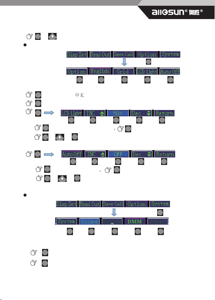
User Options
Main Menu
User Options Menu
Select Language \English
Open \ close the screen grid
Increase the brightness of the LCD Reduce the brightness of the LCD
or Or Return to the previous menu
Increase the auto-off time Reducing the auto-off time
or Or Return to the previous menu
System
Main Menu
Scope ,Oscilloscope mode
DMM
F1
F4
F1
F1
F1
F2
F2
F2
F2
F2
F3
F3
F4
F4
F4
F4
F5
F5
F5
F5
F5
F1 F2 F3 F4 F5
F1 F2 F3 F4 F5
F1 F2 F3 F4 F5
F4

EM1230 Handheld Digital Oscilloscope User ,s Manual
18
Adjust This function is not use to users
3.2.2 DMM MENU
Main Menu
System Menu
DMM Menu
Select the DC voltage \ AC voltage
Manually adjust the voltage range 600mV\6V\60V\600V\1000V
Select the Resistance \ Continuity \ Diode \ Capacitance measurements
Note:Multimeter automatic measurement mode by default
Manuall
Manually adjustable capacitance range:6nF\60nF\600nF\6uF\60uF\600uF\6mF
Select DC \ AC current
Set current coefficient Select the position to be adjusted.
Increased or Decrease the number
Return to the previous menu
Exit multimeter mode, return the oscilloscope to measure
F5
F5
F4
F1
F1
F2
F2
F3
F3
F3
F4
F4
F5
F5
MENU

UserEM1230 Handheld Digital Oscilloscope ,s Manual
19
Chapter II Use instrument
1 Oscilloscope
SCOPE mode provides a display of signal patterns from either CH A or CH B over times
ranging from 10ns to 2Hours per division, and for voltage ranges from 10mV to 500 V full
scale.
Using Single and Dual Input Scope Mode The instrument can be configured to show scope
displays for either CH A or CH B signals: In DUAL INPUT SCOPE mode, both CH A and CH
B may be displayed at the same time.
Use SINGLE INPUT SCOPE mode if you want to measure a single signal, INPUT B is turned
off.
Use DUAL INPUT SCOPE mode if you want to simultaneously measure two signals.
1.1 Test connection
The figure below shows typical test connectivity applications Oscilloscope:
1) CHA, CHB connected oscilloscope probe
2) Channel multimeter:Multimeter Test Leads
Table pen multimeter to measure
voltage, current (with clamp),
Resistance \ off \ diodes, capacitors,
as well as trigger channel
Oscilloscope B
channel
measurement
probe
Oscilloscope A
channel
measurement
probe
Table of contents
Popular Test Equipment manuals by other brands


Dynascan
Dynascan MediTEST user guide

Keysight Technologies
Keysight Technologies N7015A Quick Start and Accessories Guide

AEMC
AEMC 6416 Service/Calibration Manual

Industrial Test Systems
Industrial Test Systems Spa eXact EZ quick start guide

Ametek
Ametek JOFRA HPC600 user manual

SKF
SKF TKRS 20 Instructions for use


