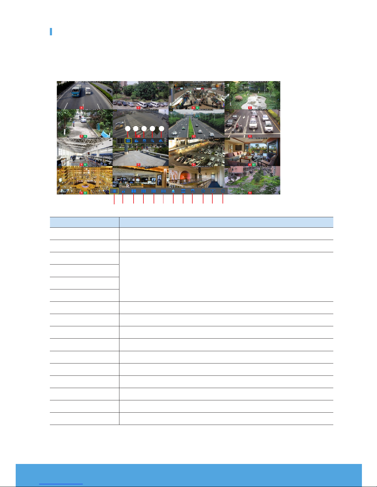
Samsung Wisenet SNK-D85121BF User manual

English _1
ALL-IN-ONE SECURITY SYSTEM
Quick Start Guide
KIT MODEL
SNK-D85121BF
NVR MODEL
SNR-D5401
Thank you for purchasing the NVR Security System.
Follow the simple steps in this guide to set up and start using your new system.
If you have any questions or need help installing your new product, please contact our free technical support.
Telephone: 1-877-349-3149
9am - 9pm EST, Monday - Friday
Web: www.samsungsv.com
❒Front
❒Back
`The appearance of power adaptor differs depending on sales region.
Part Name Function
1e-SATA Connect to e-SATA HDD
2VGA Output Connect to VGA monitor
3AUDIO OUT No Function
4LINE IN No Function
5LAN Port LAN Port for POE Power supply
6Power Switch On/Off
7Power Supply Connect to power cable
8USB USB port for upgrade or backup
9HDMI Port Connect to HDMI monitor
0WAN Port WAN port for internet
e-SATA
HDMI
Power Switch
34 2 15
6
7
890

2_ English
Startup Wizard
After the NVR Startup is completed, the Startup wizard will be displayed. If you do not want to make any additional changes to your
settings when it reboots, check “To disable Startup Wizard after reboot”.
Wizard setting menu includes:Homepage, Network setup, IPC setup, Record Schedule and hard disk maintenance.
• Homepage
• Admin password setting
• Hard drive management
• Network setup
• IPC setup
• Video recording Schedule
• General system configuration
• E-mail setting
• DDNS setting
1.
Set Admin Password
Please create a username and password for your NVR. Password MUST
be 8~13 characters long. When password is 8~9 characters long, it
should be with at least a combination of letters, digits and special sym-
bols. If it is 10~13 characters long, it should be with at least a combination
of two types of characters. 4 or more contiguous or repeated characters
or key arrangement are prohibited, for example 1111, 1234, abcd, qwerty.
Retype password: Re-enter the password set above.
2.
Hard Drive Management
New hard drive(s) connected must be formatted before use. Upon
connection, it will indicate to format new hard drive. Click on “Select” to
select the unformatted hard drive. Click on “Format HDD” to pop up the
user login window and enter the password to log in. A notice window will
indicate “Entire Data Will Be Erased. do You Want To Continue?”. Click
“OK” to format the disk. When the progress bar is complete, the format-
ting process is completed.
3.
Network setup
In DHCP mode, the router will automatically allocate IP address to the
NVR. If the NVR fails to obtain an IP address, refer to the NVR Router
Guide. If the problem still cannot be resolved, contact technical support.

English _3
4.
IPC Setup
User may add and delete IPC.
5.
Video Recording Schedule
Select the channel and the date to be set. One week’s schedule can be
set. The record “schedule” of the current channel can be copied to any
other channel or all channels.
M`If there is no color in the record menu and record search, there is no recording
saved.
`“Green” stands for normal record and “yellow” stands for motion record.
6.
General System Configuration
You can set date, time, date format, time format, language, video format
and menu timeouts.

4_ English
7.
Email Setting
Receive or Send NVR alarm email and set parameters like email address,
SSL, email enable, and interval.
• Encryption: Disable, SSL, TLS and Auto optional. Auto means it can
detect the encryption type automatically. It is recommended to set the
encryption type as Auto.
• SMTP Port: Mail sending port used by SMTP (Simple Mail Transfer
Protocol). Server is generally Port 25 or Port 465 when SSL is used by
Gmail.
• SMTP Server: Enter the address of the server for the mailbox in use.
• User Name: Enter a server to connect to. For example, email “aaa@
gmail.com” should correspond to server “smtp.gmail.com”
• Password: Enter the password of the SMTP server user.
• Sender Address: Sender’s email address, which must correspond to the server used. For example, email “aaa@gmail.
com” should correspond to server “smtp.gmail.com”.
• Receiver 1/2/3: Recipient’s mail address, used to receive alarm image and message from NVR side. If system alarms
continually and sends email images frequently, save the images to another location or remove them, so as to avoid
excessive space occupation and thereby affect your normal use of mailbox.
• Time Interval: A mail will be sent every three minutes by default. If the time interval for mail notification is set too short,
email server may deem mails as junk mails, so they cannot be transferred normally.
• Click on “Test Email”. If connection succeeds “Test E-mail” will be sent out.
8.
DDNS SETTING
User may set DDNS under network type of PPPoE/Static/DHCP after ap-
plying dynamic domain service. User may remotely access NVR through
domain by using browser in the form of http://applied domain: mapped
HTTP port number when using DDNS domain name to access NVR.
• Server address: Select dynamic domain name server provider.
Available domain name servers (HANWHA-SECURITY, DDNS_3322,
DYNDNS, NO_IP, CHANGEIP, DNSEXIT)
• Domain name: Dynamic domain name of the host obtained from
dynamic domain name service provider upon registration, for example,
nvr2016.no-ip.org.
• User Name: The user name registered upon application for dynamic
domain name.
• Password: The password set upon registration.
• Click on “Test DDNS”. If connection is made, it will indicate “DDNS Test is Successful!”. Perform remote access to the
NVR by using dynamic domain name, for example, http://ddns.hanwha-security.com/snb5000: HTTP port number (e.g.
19010)
9.
Click on “Save” to finish setting of startup wizard.

English _5
Popup Menu
After completing the system initialization, right click on your mouse on the preview interface or slide the mouse to the bottom of
screen to open the Pop-up Menu. Here, you could set parameter settings and switch betweenMain Menu, Multi-Pics, Record
Search, Sequence and Streams.
The options in the pop-up menu mayvaryaccording to different parameter settings. The options in the menu will be explained in
detail in the following chapters.
Component Name Function
1Main Menu Access the main menu.
2Manually Lock Screen Sign out or access sign-in page.
34-Channel Layout
Display four channels of video/ Display nine channels of video/Display twelve channels of video/ Display sixteen
channels of video
49-Channel Layout
512-Channel Layout
616-Channel Layout
7More Layout Display more channels of video.
8Stream Switch Switch between Main Stream and Sub Stream.
9View Image Quality Switch among Realtime, Balanced and Smooth.
0SEQ Start or stop SEQ.
!Playback Replay video recorded.
@Information System Information.
#Record Enable or disable manual recording.
$Instant Playback Display channel name Quick playback of video of last 5 minutes
%Zoom Hold and drag mouse cursor to select a frame of current video to zoom in
^Color Adjust the color of video
1 2 3 4 5 6 7 8 9 0 ! @
#8 $ % ^

6_ English
Main Menu Guide
Parameter
Record Search
Device
System
Advanced
Shutdown
Display
Record
Network
Alarm
General
HDD
Events
General
Users
Log
Info
Events
Maintain
IP Channels
Record
Network
Live
Record Schedule
Switch
Output
Mainstream
Email
Image control
Substream
Email Schedule
Privacy Zone
Mobliestream
DDNS
Motion
General
DST
NTP
Main Menu
Info
Channel Info
RTSP
Record Info

English _7
Main Menu
To enter the main menu screen, left click on the mouse on LIVE mode or press the [Menu] button on remote controller. You can also
click [ ] icon on the toolbar to enter the main menu screenas shown in Picture on the left.
Menu will be locked if left idle and you will have to enter the password again.
In Main Menu mode, you can changesettings for Parameter, Record Search, Device, System, Advanced and Shutdown.
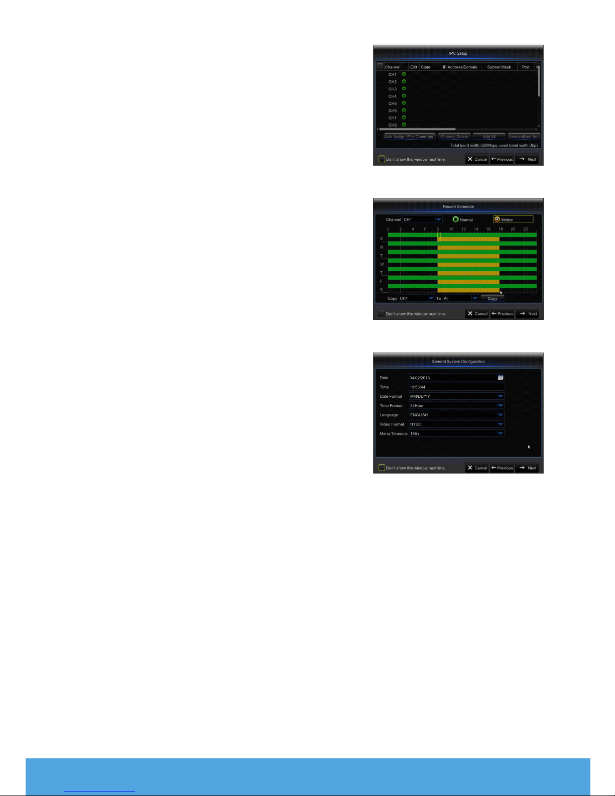
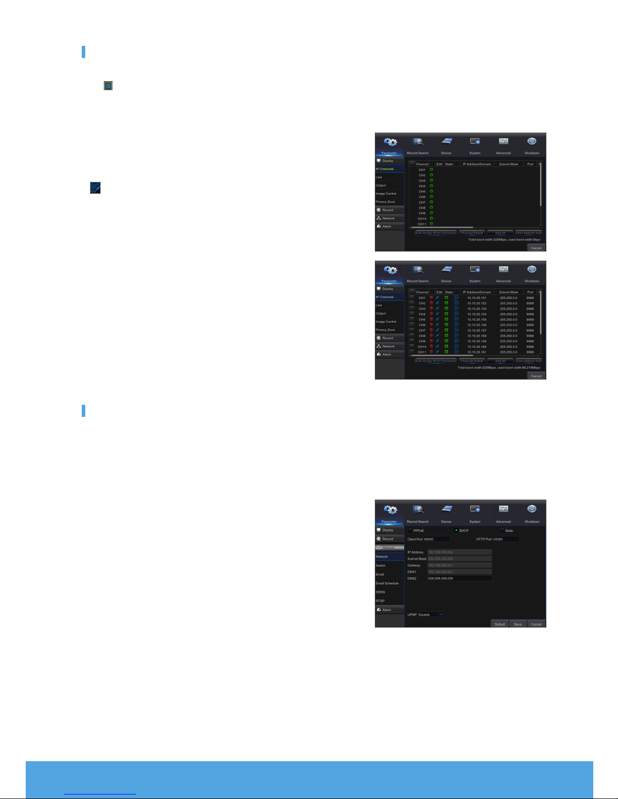
Go to “Main Menu” ; “Parameter” ; “Display” ; “IP Channels” to enter into the interface.
• Channel : IPC camera channel.
• Edit : Modify the name of IPC and location of channel name, change to other
IPC or protocols, etc.
• State : Status of IPC, on-line or off line
• : Modify IP address of IPC.
• IP Address/Domain : IP address of the IPC connected.
• Subnet Mask : Subnet mask of IPC.
• Port : Client port of IPC.
• Manufacturer : Manufacturer of IPC.
• Device type : Device Type of IPC.
• Protocol : Access protocol for IPC connected to NVR.
• MAC Address : MAC address of IPC.
• Software Version : Current firmware version of IPC.
• Auto Assign IP to Camera(s) : Auto Assign IP to IPC.
• Channel Delete : Select one channel and click Channel Delete to delete IPC.
• Add All : Add All IPC.
• User-defined Add : To add the IP cameras as user defined.
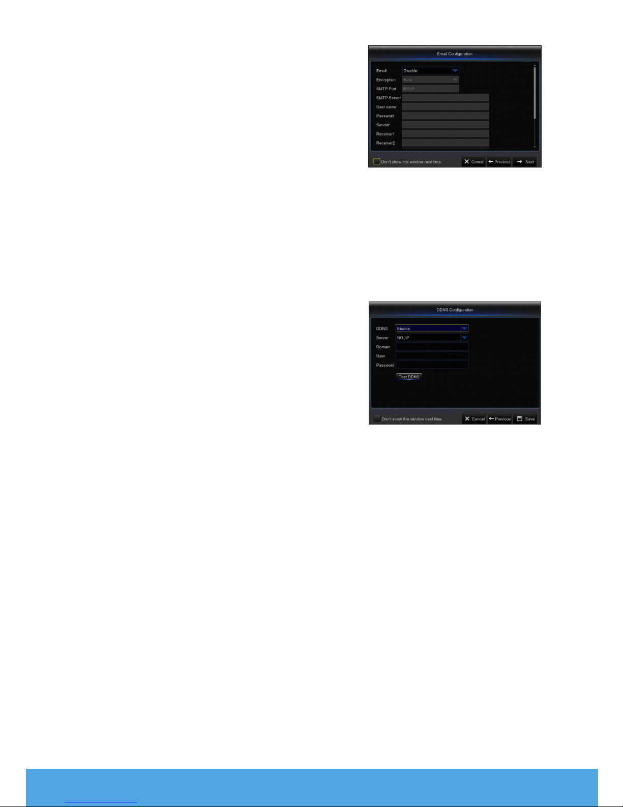
Network
Go to “Main Menu” ; “Parameter” ; “Network” to enter into the interface.
Select the type of network connection (PPPoE, DHCP, Static) and set Port, then user may remotely control the monitoring,
recording, playback or backup of the NVR through the network.
Take DHCP as an example. In this mode, the router automatically assigns IP address for the NVR. After restarting the NVR or DHCP
server, the IP address obtained by the NVR may be different. As a result, user should check the IP address and port number for
each remote access of the NVR. The operation procedure is as follows:
1.
Select DHCP, click Save and refresh the NVR. Input Client Port and HTTP
Port (the two values must not be the same).
2.
Set obtained IP address of the NVR and the mapping port.
3.
Remotely visit the NVR by IP address: http://Public network IP: HTTPport
number (such as 00080)
`For PPPoE, Static and DHCP, after setting IP address of NVR, the extranet port shall be
mapped on the router before visiting NVR through public network.
M`Save after setting to make effective. If there are multiple NVR in a LAN, make sure their
MAC addresses are different.

8_ English
Web Application Manager
❒Download and Installation of Plugin.
Windows 7 : You may need to setup the user authority for the remote controlor you may not beable to back-up your hard drive or record.
Windows Vista : Start ; Setup ; Control Panel. Set user authority in control panel shown on the picture below. Remove the check
“√” in front of the option “Use UAC to help protect your computer” and click OK to confirm.
WIN7
Vista
M`If the web plugin is not downloaded successfully, please check if your browser’s safety level or
firewall setting is too high. Please open IE browser ;[Menu Bar] Tools ;Internetoptions ;
Security ;Internet ;Custom level ;Enable the following options.
Download and installation of plugin for IE
Run your web browser as administrator and input the IP address and HTTP port
of NVR, such as: http://192.168.1.200:80.

English _9
Save plug in, and then click Install on pop-up box of the Setup-Webplugin to
install. Restart the browser, and then enter the NVR IP address plus HTTP port,
such as http://192.168.1.200:80, to log in.
Download and Installation of plug in for Safari
Input the IP address and HTTP port on Safari, such as http://192.168.1.200:80,
and thenclick download to download the plug in. Click Download icon to have the
plug-in ‘WebPluginN.dmg’ downloaded.Double click ‘WebPluginN.dmg’. Double
click ‘SurveillanceClient.pkg’and then click Continue and Install. Enter user name
and password to install, thenclick Close to finish installation. Restart the browser,
and then enter the NVR IP address plus HTTP port, such as
http://192.168.1.200:80, to log in.
M`The above instructions are for first time installations. You can use the same plug-in for IE
and Google Chrome. If plug-in for windows OS was installed on IE or Google Chrome once,
you need to use IE which needs to be run as administrator.Use Google Chrome to log in to
NVR.
If you use Google Chrome to log in, please use Version 41 or lower. If you use V42 to V44 to
log in, you need to enable NPAPI plug-ins. You can enter chrome://flags/#enable-npapi on
URL bar of Google Chrome to find and enable NPAPI. Please note that it doesn’t support
V45 or above.
When you do a firmware upgrade, you have to re-download and re-install the plug-in. Based
on different situations, it may not be able to install the plug-in through browsers. In this
case, please copy and install the plug in on the CD attached(Web_plugin_Windows_YYYY_
MM_DD.exefor Windows system, and SurveillanceClient_Mac_YYYY_MM_DD.dmg for
Mac).

10_ English
❒View NVR Remotely Through Browsers
After the plug-in isinstalled and the IP address and HTTP port is entered, you can
go to the following log in interface. Enter the username and password you created
on the local NVR, then select Sub Stream or Mobile Stream (In general, select Sub
stream for intranet and Mobile stream for extranet), and select language. Click
‘Open All Channels Preview’ to open all live pictures. Press Login to visit NVR
remotely.
Live Interface
Log in and go to live view.

English _11
Mobile App
❒Android Phones/Tablets
1.
Open Play Store to search for WiseView and click “INSTALL”.
2.
After installation, open WiseView and select “Device”. Then click [ ] to add new device.
Scan QR code under Information page. Then input client port, user name and password, and then click Save to log into the
NVR.

12_ English
❒iPhone/iPad
1.
Open App Store to search for WiseView, and click icon [ ] to install.
2.
Open WiseView, and go to Device. Click [ ] to add new device. Scan QR code under Information page. Then input client
port, user name and password, and then click Save to log into the NVR.

English _13
MEMO

14_ English
Camera Installation Template
To make the camera installation easier, you can tear off this page and use it as reference.
This template is used to install the camera on the wall
TEMPLATE
CAMERA FRONT
Screw holes for
the Camera
installation

English _15
MEMO

This manual suits for next models
1
Table of contents
Other Samsung Wisenet Security System manuals
Popular Security System manuals by other brands

Kompernass
Kompernass TA 120 A2 operating instructions

SmartPool
SmartPool Pool Eye PE24 Installation and operation manual

Contigo
Contigo 1600 installation guide

Triton
Triton TRIT001-US Installation guide and user's manual

M-system
M-system M1EAXV-1 instruction manual

Siemens
Siemens SIRIUS 8WD42 operating instructions