Samsung MX-ST50B User manual

MX-ST50B
USER MANUAL

ENG - ii ENG - iii
SAFETY INFORMATION FCC Caution :
• Any changes or modications not expressly
approved by the party responsible for
compliance could void the user’s authority to
operate this equipment.
• This product satises FCC regulations when
shielded cables and connectors are used to
connect the unit to other equipment.
To prevent electromagnetic interference with
electric appliances, such as radios and
televisions, use shielded cables and
connectors for connections.
Class B FCC Statement
This equipment has been tested and found to
comply with the limits for a Class B digital device,
pursuant to Part 15 of the FCC Rules. These limits
are designed to provide reasonable protection
against harmful interference in a residential
installation. This equipment generates, uses and
can radiate radio frequency energy and, if not
installed and used in accordance with the
instructions, may cause harmful interference to
radio communications. However, there is no
guarantee that interference will not occur in a
particular installation. If this equipment does
cause harmful interference to radio or television
reception, which can be determined by turning
the equipment off and on, the user is encouraged
to try to correct the interference by one of the
following measures:
• Reorienting or relocating the receiving
antenna.
• Increasing the separation between the
equipment and receiver.
• Connecting the equipment to an outlet that is
on a different circuit than the radio or TV.
• Consulting the dealer or an experienced
radio/TV technician for help.
SAFETY WARNINGS
TO REDUCE THE RISK OF ELECTRIC SHOCK, DO
NOT REMOVE THE COVER (OR BACK).
NO USER-SERVICEABLE PARTS ARE INSIDE.
REFER SERVICING TO QUALIFIED SERVICE
PERSONNEL.
Refer to the table below for an explanation of
symbols which may be on your Samsung product.
CAUTION
RISK OF ELECTRIC SHOCK.
DO NOT OPEN.
This symbol indicates that high voltage
is present inside. It is dangerous to
make any kind of contact with any
internal part of this product.
This symbol indicates that this product
has included important literature
concerning operation and maintenance.
Class II product : This symbol indicates
that a safety connection to electrical
earth (ground) is not required.
If this symbol is not present on a
product with a power cord, the product
MUST have a reliable connection to
protective earth (ground).
AC voltage : Rated voltage marked
with this symbol is AC voltage.
DC voltage : Rated voltage marked
with this symbol is DC voltage.
Caution. Consult Instructions for use :
This symbol instructs the user to
consult the user manual for further
safety related information.
WARNING
• To reduce the risk of re or electric shock, do
not expose this appliance to rain or moisture.
• This product contains chemicals known to the
State of California to cause cancer and birth
defects or other reproductive harm.
• The battery (battery or batteries or battery
pack) shall not be exposed to excessive heat
such as sunshine, re or the like.
CAUTION
• Do not expose this apparatus to dripping or
splashing. Do not put objects lled with
liquids, such as vases, on the apparatus.
• To turn this apparatus off completely, you
must pull the power plug out of the wall
socket. Consequently, the power plug must
be easily and readily accessible at all times.
FCC NOTE (for U.S.A):
FCC Supplier’s Declaration of Conformity
Responsible Party - U.S. Contact Information:
Samsung Electronics America, Inc.
85 Challenger Road.
Ridgeeld Park, NJ 07660
Phone: 1-800-SAMSUNG (726-7864)
FCC Compliance Statement :
This device complies with Part 15 of the FCC Rules.
Operation is subject to the following two
conditions:
(1) This device may not cause harmful
interference, and (2) this device must accept any
interference received, including interference that
may cause undesired operation.

ENG - ii ENG - iii
SAFETY INFORMATION FCC Caution :
• Any changes or modications not expressly
approved by the party responsible for
compliance could void the user’s authority to
operate this equipment.
• This product satises FCC regulations when
shielded cables and connectors are used to
connect the unit to other equipment.
To prevent electromagnetic interference with
electric appliances, such as radios and
televisions, use shielded cables and
connectors for connections.
Class B FCC Statement
This equipment has been tested and found to
comply with the limits for a Class B digital device,
pursuant to Part 15 of the FCC Rules. These limits
are designed to provide reasonable protection
against harmful interference in a residential
installation. This equipment generates, uses and
can radiate radio frequency energy and, if not
installed and used in accordance with the
instructions, may cause harmful interference to
radio communications. However, there is no
guarantee that interference will not occur in a
particular installation. If this equipment does
cause harmful interference to radio or television
reception, which can be determined by turning
the equipment off and on, the user is encouraged
to try to correct the interference by one of the
following measures:
• Reorienting or relocating the receiving
antenna.
• Increasing the separation between the
equipment and receiver.
• Connecting the equipment to an outlet that is
on a different circuit than the radio or TV.
• Consulting the dealer or an experienced
radio/TV technician for help.
FCC Radiation Exposure Statement :
This equipment complies with FCC radiation
exposure limits set forth for an uncontrolled
environment. This equipment should be installed
and operated so there is at least 8 inches (20 cm)
between the radiator and your body. This device
and its antenna(s) must not be co-located or
operated in conjunction with any other antenna or
transmitter.
CALIFORNIA USA ONLY (Applicable for
networking models only.)
This Perchlorate warning applies only to primary
CR(Manganese Dioxide) Lithium coin cells in the
product sold or distributed ONLY in California
USA “Perchlorate Material - special handling may
apply, See www.dtsc.ca.gov/hazardouswaste/
perchlorate.”
Dispose unwanted electronics through an
approved recycler. To nd the nearest recycling
location, go to our website:www.samsung.com/
recycling Or call, 1‐800‐SAMSUNG
WARNING: Cancer and Reproductive Harm
- www.P65Warnings.ca.gov.
Important Safety Instructions
Read these operating instructions carefully
before using the unit. Follow all the safety
instructions listed below. Keep these operating
instructions handy for future reference.
1. Read these instructions.
2. Keep these Instructions.
3. Heed all warnings.
4. Follow all instructions.
5. Do not use this apparatus near water.
6. Clean only with dry cloth.
7. Do not block any ventilation openings.
Install in accordance with the manufacturer’s
instructions.
WARNING
• To reduce the risk of re or electric shock, do
not expose this appliance to rain or moisture.
• This product contains chemicals known to the
State of California to cause cancer and birth
defects or other reproductive harm.
• The battery (battery or batteries or battery
pack) shall not be exposed to excessive heat
such as sunshine, re or the like.
CAUTION
• Do not expose this apparatus to dripping or
splashing. Do not put objects lled with
liquids, such as vases, on the apparatus.
• To turn this apparatus off completely, you
must pull the power plug out of the wall
socket. Consequently, the power plug must
be easily and readily accessible at all times.
FCC NOTE (for U.S.A):
FCC Supplier’s Declaration of Conformity
Responsible Party - U.S. Contact Information:
Samsung Electronics America, Inc.
85 Challenger Road.
Ridgeeld Park, NJ 07660
Phone: 1-800-SAMSUNG (726-7864)
FCC Compliance Statement :
This device complies with Part 15 of the FCC Rules.
Operation is subject to the following two
conditions:
(1) This device may not cause harmful
interference, and (2) this device must accept any
interference received, including interference that
may cause undesired operation.

ENG - iv ENG - v
8. Do not install near any heat sources such as
radiators, heat registers, stoves, or other
apparatus (including ampliers) that produce
heat.
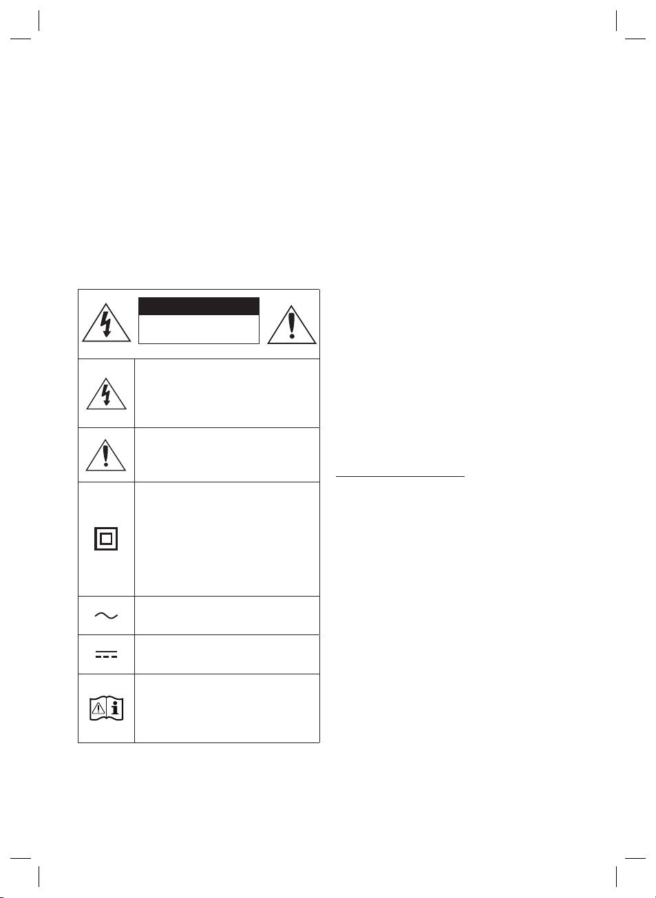
9. Do not defeat the safety purpose of the
polarized or grounding-type plug.
A polarized plug has two blades with one
wider than the other. A grounding type plug
has two blades and a third grounding prong.
The wide blade or the third prong are
provided for your safety. If the provided plug
does not t into your outlet, consult an
electrician for replacement of the obsolete
outlet.
10.Protect the power cord from being walked
on or pinched particularly at plugs,
convenience receptacles, and the point
where they exit from the apparatus.
11. Only use attachments/accessories specied
by the manufacturer.
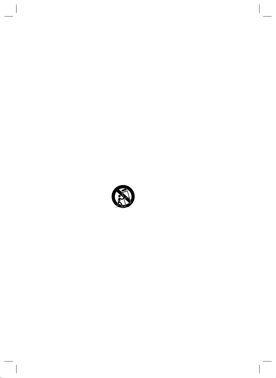
12. Use only with the cart, stand,
tripod, bracket, or table
specied by the manufacturer,
or sold with the apparatus.
When a cart is used, use caution when
moving the cart/apparatus combination to
avoid injury from tip-over.
13. Unplug this apparatus during lightning
storms or when unused for long periods of
time.
14. Refer all servicing to qualied service
personnel. Servicing is required when the
apparatus has been damaged in any way,
such as power-supply cord or plug is
damaged, liquid has been spilled or objects
have fallen into the apparatus, the apparatus
has been exposed to rain or moisture, does
not operate normally, or has been dropped.
To avoid deterioration of waterproof
Check the following and use the unit correctly.
• Deformation or damage from dropping the
unit or subjecting it to mechanical shock may
cause deterioration of the waterproof.
• This unit does not have a design that is
resistant to water pressure. Use of the unit in
a location where high water pressure is
applied, such as in the shower, may cause a
malfunction.
• Do not pour high-temperature water or blow
hot air from a hair dryer or any other
applicance on the unit directly. Also never use
the unit in a place subject to high
temperatures, such as in a sauna or near a
heat source.
• Handle the cap with care. Port cover and AC
plug cover plays a very important role in
maintenance of the waterproof and dust
proof performance. When using the unit,
make sure that the cap is closed completely.
When closing the cap, be careful not to allow
foreign objects inside. If the cap is not closed
completely the waterproof and dust proof
performance may deteriorate and may cause
a malfunction of the unit as a result of water
or dust particles entering the unit.
PRECAUTIONS
1. Ensure that the AC power supply in your
house complies with the power
requirements listed on the identication
sticker located on the rear of your product.
Install your product horizontally, on a
suitable base (furniture), with enough space
around it for ventilation (3~4 inches). Make
sure the ventilation slots are not covered. Do
not place the unit on ampliers or other
equipment which may become hot. This unit
is designed for continuous use.
To fully turn off the unit, disconnect the AC
plug from the wall outlet. Unplug the unit if
you intend to leave it unused for a long
period of time.
2. During thunderstorms, disconnect the AC
plug from the wall outlet. Voltage peaks due
to lightning could damage the unit.
3. Do not expose the unit to direct sunlight or
other heat sources. This could lead to
overheating and cause the unit to
malfunction.
4. Protect the product from moisture (i.e.
vases), and excess heat (e.g. a replace) or
equipment creating strong magnetic or
electric elds. Unplug the power cable from
the AC wall socket if the unit malfunctions.
Your product is not intended for industrial
use. It is for personal use only. Condensation
may occur if your product has been stored in
cold temperatures. If transporting the unit
during the winter, wait approximately
2 hours until the unit has reached room
temperature before using.
5. The battery used with this product contains
chemicals that are harmful to the
environment. Do not dispose of the battery
in the general household trash. Do not
expose the battery to excess heat, direct
sunlight, or re. Do not short circuit,
disassemble, or overheat the battery.
CAUTION : Danger of explosion if the battery
is replaced incorrectly. Replace only with the
same or equivalent type.

ENG - iv ENG - v
To avoid deterioration of waterproof
Check the following and use the unit correctly.
• Deformation or damage from dropping the
unit or subjecting it to mechanical shock may
cause deterioration of the waterproof.
• This unit does not have a design that is
resistant to water pressure. Use of the unit in
a location where high water pressure is
applied, such as in the shower, may cause a
malfunction.
• Do not pour high-temperature water or blow
hot air from a hair dryer or any other
applicance on the unit directly. Also never use
the unit in a place subject to high
temperatures, such as in a sauna or near a
heat source.
• Handle the cap with care. Port cover and AC
plug cover plays a very important role in
maintenance of the waterproof and dust
proof performance. When using the unit,
make sure that the cap is closed completely.
When closing the cap, be careful not to allow
foreign objects inside. If the cap is not closed
completely the waterproof and dust proof
performance may deteriorate and may cause
a malfunction of the unit as a result of water
or dust particles entering the unit.
PRECAUTIONS
1. Ensure that the AC power supply in your
house complies with the power
requirements listed on the identication
sticker located on the rear of your product.
Install your product horizontally, on a
suitable base (furniture), with enough space
around it for ventilation (3~4 inches). Make
sure the ventilation slots are not covered. Do
not place the unit on ampliers or other
equipment which may become hot. This unit
is designed for continuous use.
To fully turn off the unit, disconnect the AC
plug from the wall outlet. Unplug the unit if
you intend to leave it unused for a long
period of time.
2. During thunderstorms, disconnect the AC
plug from the wall outlet. Voltage peaks due
to lightning could damage the unit.
3. Do not expose the unit to direct sunlight or
other heat sources. This could lead to
overheating and cause the unit to
malfunction.
4. Protect the product from moisture (i.e.
vases), and excess heat (e.g. a replace) or
equipment creating strong magnetic or
electric elds. Unplug the power cable from
the AC wall socket if the unit malfunctions.
Your product is not intended for industrial
use. It is for personal use only. Condensation
may occur if your product has been stored in
cold temperatures. If transporting the unit
during the winter, wait approximately
2 hours until the unit has reached room
temperature before using.
5. The battery used with this product contains
chemicals that are harmful to the
environment. Do not dispose of the battery
in the general household trash. Do not
expose the battery to excess heat, direct
sunlight, or re. Do not short circuit,
disassemble, or overheat the battery.
CAUTION : Danger of explosion if the battery
is replaced incorrectly. Replace only with the
same or equivalent type.
Others
• Do not use or leave the unit in an extremely
cold or hot environment (temperature outside
the range 5 °C - 35 °C). If the unit is used or
left in outside the above range, the unit may
automatically stop to protect internal
circuitry.
• At high temperature, the charging may stop
or the volume may reduce to protect the
battery.
• Even if you do not intend to use the unit for a
long time, charge the battery to its full
capacity once every 6 months to maintain its
performance.

ENG - vi ENG - vii
ABOUT THIS MANUAL
The user manual has two parts: this simple paper USER MANUAL and a detailed FULL MANUAL you can
download.
USER MANUAL
See this manual for safety instructions, product installation,
components, connections, and product specications.
FULL MANUAL
You can access the FULL MANUAL on Samsung’s on-line
customer support center by scanning the QR code on the left.
To see the manual on your PC or mobile device, download the
manual in document format from Samsung’s website.
(https://www.samsung.com/us/support/downloads/)
Design and specications are subject to change without prior notice.
Sound Tower is a new name for Giga Party Audio.
CONTENTS
01 Checking the Components 2
Inserting Batteries before using the Remote Control
(AAA batteries X 2) ------------------------- 2
02 Product Overview 3
Top Panel of the Sound Tower ------------------------- 3
Rear Panel of the Sound Tower ------------------------- 4
03 Connecting the Sound Tower 5
Connecting Electrical Power ------------------------- 5
How to use Audio Group ------------------------- 6
04 Connecting an External Device 12
Connecting using an Analog Audio (AUX) Cable ------------------------- 12
Connecting a mobile device via Bluetooth ------------------------- 13
Connecting the Samsung TV via Bluetooth ------------------------- 16
05 Connecting a USB Storage Device 17
Software Update ------------------------- 17
06 Using the Remote Control 18
How to Use the Remote Control ------------------------- 18

ENG - 2 ENG - 3
01 CHECKING THE COMPONENTS
Sound Tower Main Unit Remote Control (AH81-11472A) /
Batteries
Power Cord
(AH81-11474A)
• For more information about the power supply and power consumption, refer to the label attached
to the product. (Label: Rear of the Sound Tower Main Unit)
• To purchase additional components or optional cables, contact a Samsung Service Center or
Samsung Customer Care.
• When moving the product, do not drag or pull the product from the ground. Lift the product when
moving the product.
Inserting Batteries before using the Remote Control
(AAA batteries X 2)
Slide the battery cover in the direction of the arrow
until it is completely removed. Insert 2 AAA
batteries (1.5V) oriented so that their polarity is
correct. Slide the battery cover back into position.
02 PRODUCT OVERVIEW
Top Panel of the Sound Tower
BASS
Remote
Sensor
When operating the Sound Tower system, please aim the front of the remote control at
the remote sensor.
Display
Window
Displays operating messages or current status of the Sound Tower system.
You also need to add a description of these ve lamp effects
BT USB AUX1 AUX2 Power
Power Turns the Sound Tower on and off.
Light Press the (Light) button to turn the Lighting Mode on.
Source
Press to select a source connected to the Sound Tower.
Press and hold the (Source)
button for more than 5 seconds
to enter the
“SEARCHING TV” mode.
Play/Pause
• Play/Pause
Press the button to pause a music le temporarily.
When you press the button again, the music le plays.
• Demo play
Press and hold the
button for more than 5 seconds to start the Demo play while
the system is turned on. No VFD display, 5 LEDS ashing simultaneously and it plays
demo music for 60 seconds.
– Please be careful as it may play louder than the set volume.
Volume down Press the (Volume down) button to lower the volume.
Volume up Press the (Volume up) button to raise the volume.
BASS Press the BASS button to use the powerful bass sound.

ENG - 4 ENG - 5
Rear Panel of the Sound Tower
POWER
ECHOVOL
USB
(5V2.1A)
AUX1
MIC
ECHOVOL
USB
(5V 2.1A)
AUX 1
MIC
Bluetooth
PAIRING
Press the PAIRING button to enter the without VFD, the third LED alternates red,
green and blue.
ADD STEREO Press the ADD STEREO button to connect to another Sound Tower wirelessly.
GROUP PLAY Press the GROUP PLAY button to connect up to ten Sound Tower systems wirelessly.
USB
Connect a USB device to the USB ports on the main unit.
If you connect your cell phone to the USB port, you can charge it.
• Press the (Source) button to select USB.
ECHO You can give an echo effect to the sound from a connected microphone (MIC) by
adjusting the ECHO knob.
VOL Use the VOL knob to adjust the volume of a connected microphone (MIC).
MIC Connect your microphone to the MIC jack.
GROUP PLAY
OUT
Terminals
Use an Audio Cable (not supplied) to connect GROUP PLAY (OUT) terminals on the
main unit to Audio In on an external analog output device.
AUX2/GROUP
PLAY IN
Terminals
Use an Audio Cable (not supplied) to connect AUX2 (IN) terminals on the main unit to
Audio Out on an external analog output device.
AUX1 Use an Audio (AUX) Cable (not supplied) to connect AUX1 jack on the main unit to
Audio Out on an external device.
Power Connect the power cord to the Power jack and connect the other end of the power
cord to a wall socket to supply electrical power to the Sound Tower.
03 CONNECTING THE SOUND TOWER
Connecting Electrical Power
Use the power cord to connect the Sound Tower to an electrical outlet in the following order:
Connect the power cord to the Sound Tower and then to a wall socket.
See the illustrations below.
• For more information about the required electrical power and power consumption, refer to the
label attached to the product. (Label: Rear of the Sound Tower)
Rear of Sound Tower
POWER
ECHOVOL
USB
(5V2.1A)
AUX1
MIC
Connecting
Electrical Power

ENG - 6 ENG - 7
Connecting the wireless Group Play mode
You can connect up to ten Sound Tower systems with the wireless Group Play function.
HOST
SUB 1 SUB 2
1. Press the GROUP PLAY button on the HOST Sound Tower system. The “HOST” message appears
on the display of the HOST Sound Tower and the LED blinks on the GROUP PLAY button.
2. Press the GROUP PLAY button on the 2nd Sound Tower system (SUB 1). The GROUP PLAY button
on both systems stops blinking.
3. Press the GROUP PLAY button on the 3rd Sound Tower system (SUB 2). No VFD display, voice
prompt instead the GROUP PLAY button on the system stops blinking.
4. If you want to add more Sound Tower systems, repeat step 3.
5. Play music on the HOST Sound Tower. Sound outputs from all the connected systems.
NOTES
• If Sound Tower is connected with Samsung TV, Wireless Group Play is not available.
• The wireless Group Play connection is available for any Sound Tower system.
• Environmental conditions or other factors with connected devices may have effect on playback
quality.
• If the red LED is on the GROUP PLAY button, an error has occurred in the wireless Group Play
connection. Try step 1 to step 5 again.
• The ADD STEREO button and PAIRING button on the SUB Sound Tower systems are not available
while in wireless Group Play mode.
• The ADD STEREO button on the HOST Sound Tower system is not available while in wireless Group
Play mode.
• When adding a SUB unit, if you press and hold GROUP PLAY on the SUB, before no VFD display,
voice prompt instead message appears, it will become the HOST unit instead.
How to use Audio Group
You can connect multiple audio systems in a group to create a party environment and produce higher
sound output. Set one Sound Tower as the HOST and any music played on it will be shared among any
other Sound Tower systems in the Audio group.
Connecting the wired Group Play mode
1st
Sound Tower HOST
2nd
Sound Tower
Last
Sound Tower
Continue the
connection until
the last Sound
Tower
Set up Group Play by connecting all the systems using audio cables (not supplied). Use the AUX or
(Source) button to change the source to AUX2 for every Sound Tower system except the 1st (or HOST)
Sound Tower system.
NOTES
• The 1st Sound Tower HOST can play music from any source.
• Depending on the length or characteristics of the cable, there may be a difference in operating
distance.

ENG - 8 ENG - 9
• All SUB units must be connected one by one. For example, after HOST is connected, press GROUP
PLAY button on SUB 1 to connect, and after SUB 1 is connected, you should connect SUB 2 and SUB
3 one by one sequentially.
• While using Group Play, currently connected Bluetooth devices are disconnected and Bluetooth
connection is disabled.
• Bluetooth devices can search and connect with the HOST Sound Tower only.
• When in Group Play mode, the SUB cannot connect to a Bluetooth device.
• If you power off and then power on the Sound Tower or select any source other than BT on a SUB
unit, in Group Play mode, the Group Play mode is disconnected.
• This product does not support aptX audio stream with Wireless Group Play mode.
Disconnecting the wireless Group Play mode
1. Press and hold the GROUP PLAY button over 5 seconds (HOST or SUB) after Group Play is
connected or press the GROUP PLAY button (HOST or SUB) before Group Play is connected.
• No VFD display, voice prompt instead and the LED above the GROUP PLAY button is off.
2. If you select any source other than BT on the SUB units or turn off the HOST Sound Tower, the
Group Play mode is disconnected.
• If the disconnection is made from the HOST Sound Tower, Group Play is disconnected.
LED Indications
LED STATE Description
Green Blink Waiting for a wireless Group Play connection.
Solid The wireless Group Play connection was successful.
Red Solid There is an error with the wireless Group Play connection.
NOTE
• In wireless connection, Playback quality can be unstable depending on Bluetooth environment.
For better play, please keep the device in wired Group Play mode.
Using a Smartphone and Stereo Group mode
Connect two Sound Tower and use them with your smartphone to enjoy stereo sound.
Left Sound Tower
(MAIN)
Right Sound Tower
(SUB)
1. Press the ADD STEREO button on the left Sound Tower system. The LED blinks on the ADD
STEREO button.
2. Press the ADD STEREO button on the right Sound Tower system. The LED blinks on the ADD
STEREO button.
3. When the connection is made, no VFD display, voice prompt instead.
• The MAIN Sound Tower system outputs left channel sound and the SUB Sound Tower system
outputs right channel sound. Press the ADD STEREO button on the MAIN or SUB Sound Tower
to change the sound channel of the Sound Tower.
4. Play music by connecting your smartphone to the MAIN Sound Tower and Bluetooth.
Sound is output from both Sound Tower.
NOTES
• To use the Stereo Group mode, both Sound Tower systems must be the same model.
• Environmental conditions or other factors with connected devices may have effect on playback
quality.
• If the red LED is on the ADD STEREO, an error has occured in the Stereo Group connection. Try step
1 and step 3 again.
• Remote Controller, BT PAIRING, GROUP PLAY and (Source) buttons on the SUB Sound Tower
systems are disabled while in Stereo Group mode.
• The GROUP PLAY button on the MAIN Sound Tower system is not available while in Stereo Group
mode.

ENG - 10 ENG - 11
• In mode other than “BT” (ex. USB, AUX mode), music is played only in MAIN Sound Tower and music
is not played in SUB Sound Tower.
• The lighting colors between MAIN Sound Tower and SUB Sound Tower may vary.
• The Bluetooth device has the same name as MAIN Sound Tower and SUB Sound Tower when
connected to the Bluetooth device, and only the MAIN Sound Tower can be connected.
• This product does not support aptX audio stream with Stereo Group mode.
• If you try to connect a Bluetooth device while Stereo Group is connecting, the Stereo Group mode
may fail.
Terminate the Stereo Group mode
Press the ADD STEREO button (MAIN or SUB) for at least 5 seconds after the Stereo Group is
connected.
• No VFD display, voice prompt instead appears on the display and the LED above the ADD STEREO
button is off.
LED Indications
LED STATE Description
Green Blink Waiting for a Stereo Group connection.
Solid The Stereo Group connection is successful.
Red Solid There is an error with the Stereo Group connection.
Using Samsung TV and Stereo Group mode
Connect two Sound Tower by wire and use them with Samsung TV to enjoy stereo sound.
Left Sound Tower
(MAIN)
Right Sound Tower
(SUB)
1. Refer to “Using a Smartphone and Stereo Group mode” to connect the two Sound Tower in a
Stereo Group.
2. Connect the RCA cable to the AUX2 OUT on the MAIN and AUX2 IN on the SUB as shown by using
the RCA cable (not supplied).
3. In “BT” mode, press the “AUX” button on the MAIN Sound Tower remote control for at least 5
seconds. LED indicator light ow display appears on the display.
4. When the connection is complete, the third LED ashes appears in the display and then the current
output no VFD display, voice prompt instead.
5. When the connection is complete, LED indicator light ow display message appears in the MAIN
Sound Tower display and a “SUB” appears in the SUB Sound Tower display.
• The MAIN Sound Tower outputs the left channel sound and the SUB Sound Tower outputs the
right channel sound. Press the ADD STEREO button on the MAIN or SUB Sound Tower to
change the sound channel of the Sound Tower.
6. Connect a TV and MAIN Sound Tower via Bluetooth to play music. Sound is output from both
Sound Tower.
NOTES
• To use Stereo Group mode, both Sound Tower must be the same model.
• A red light on the LED on the ADD STEREO button indicates an error in the Stereo Group
connection. Try Step 1 to 5 again.
• In Stereo Group mode, the remote control, BT PAIRING, GROUP PLAY, and (Source) buttons on
the SUB Sound Tower are disabled.
• The GROUP PLAY button on the MAIN Sound Tower is not available in Stereo Group mode.
• If Samsung TV supports a simple connection, the connection pop-up is automatically displayed on
the TV, and if you select “Yes”, it connects to the TV. If there is a previous connection history
between Samsung TV and Sound Tower, it will be connected to Samsung TV without pop-up. For a
simple connection to Samsung TV, refer to page 16.
• The lighting colors may vary between the MAIN Sound Tower and the SUB Sound Tower.
• When connecting to a TV, the names of the MAIN and SUB Sound Tower are the same in the
Bluetooth list on the TV, and only the MAIN Sound Tower can be connected.
Terminating the Stereo Group mode connection
Press the ADD STEREO button (MAIN or SUB) for at least 5 seconds after the Stereo Group is
connected.
• “OFF-STEREO MODE” appears in the display and the LED on the ADD STEREO button turns off.

ENG - 12 ENG - 13
04 CONNECTING AN EXTERNAL DEVICE
Connect to an external device via a wired or wireless network to play the external device’s sound
through the Sound Tower.
Connecting using an Analog Audio (AUX) Cable
AUX 1
- AUDIO -
R L
Mobile device / MP3 / PMP
BD / DVD player / Set-top box / Game console
0.14 inches (3.5 mm)
stereo cable (not supplied)
Audio (AUX) Cable (not supplied)
Rear of the Sound Tower
0.14 inches (3.5 mm) stereo Cable (AUX1)
1. Connect AUX1 jack on the main unit to the AUDIO OUT jack of the Source Device using an
0.14 inches (3.5 mm) stereo cable .
2. Select “AUX1” mode by pressing the (Source) button on the top panel or on the remote control.
• You can also select a source using AUX button on the remote control.
Audio Cable (AUX2)
1. Connect AUX2 (IN) terminals on the main unit to the AUDIO OUT terminals of the Source Device
using an audio cable .
2. Select “AUX2” mode by pressing the (Source) button on the top panel or on the remote
control.
• You can also select a source using AUX button on the remote control.
Connecting a mobile device via Bluetooth
When a mobile device is connected using Bluetooth, you can hear stereo sound without the hassle of
cabling.
ECHOVOL
USB
(5V2.1A)
AUX1
MIC
LIGHT
PAIRING
TEMPO
USB AUX
EFFECT
DOWN UP
EFFECT
DJ
SOUND
MODE
Bluetooth device
OR
The initial connection
1. Press and hold the PAIRING button on the remote control for more than 5 seconds to enter the
“BT PAIRING” mode.
(OR) Press the PAIRING button on the rear panel.
2. On your device, select “[AV] MX-ST50B” from the list that appears.
• After the device is connected, a third LED blinks
3. Play music les from the device connected via Bluetooth through the Sound Tower.
If the device fails to connect
• If a previously connected Sound Tower listing (e.g. “[AV] MX-ST50B”) appears in the list, delete it.
• Then repeat steps 1 and 2.
What is the difference between BT READY and BT PAIRING?
• BT READY : In this mode, you can search for previously connected TVs or connect a previously
connected mobile device to the Sound Tower.
• BT PAIRING : In this mode, you can connect a new device to the Sound Tower.
(Press and hold the PAIRING button on the remote control for more than 5 seconds or press the
PAIRING button on the rear of the Sound Tower to enter the “BT PAIRING” mode.)
Other manuals for MX-ST50B
4
Table of contents
Other Samsung Portable Speakers manuals

Samsung
Samsung EO-SG900 User manual

Samsung
Samsung DA F60 User manual

Samsung
Samsung WAM7500 User manual

Samsung
Samsung DA F60 User manual

Samsung
Samsung Level Box User manual

Samsung
Samsung DA F60 User manual

Samsung
Samsung EO-SG900 User manual

Samsung
Samsung DA F60 User manual

Samsung
Samsung EO-SG900 User manual