manuals.online logo
Brands
  1. Home
  2. •
  3. Brands
  4. •
  5. Samsung
  6. •
  7. Security Camera
  8. •
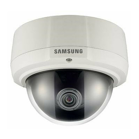
  9. Samsung C4203(P) User manual

Samsung C4203(P) User manual

This manual suits for next models

10

Other Samsung Security Camera manuals

Samsung SCC-C7453P User manual

Samsung

Samsung SCC-C7453P User manual

Samsung SCB-2010 User manual

Samsung

Samsung SCB-2010 User manual

Samsung SID-500 User manual

Samsung

Samsung SID-500 User manual

Samsung SCB-3001 User manual

Samsung

Samsung SCB-3001 User manual

Samsung SCC-B9371 User manual

Samsung

Samsung SCC-B9371 User manual

Samsung SCO-2080 User manual

Samsung

Samsung SCO-2080 User manual

Samsung C4303(P) User manual

Samsung

Samsung C4303(P) User manual

Samsung SCD-6081R User manual

Samsung

Samsung SCD-6081R User manual

Samsung SCC-C7433(P) User manual

Samsung

Samsung SCC-C7433(P) User manual

Samsung SNP-3430H User manual

Samsung

Samsung SNP-3430H User manual

Samsung SNP-6320RH User manual

Samsung

Samsung SNP-6320RH User manual

Samsung iPolis SNV-7080R User manual

Samsung

Samsung iPolis SNV-7080R User manual

Samsung SCC-B5395 User manual

Samsung

Samsung SCC-B5395 User manual

Samsung SCC-5395 User manual

Samsung

Samsung SCC-5395 User manual

Samsung Techwin SCP-2270H User manual

Samsung

Samsung Techwin SCP-2270H User manual

Samsung SND-6083 User manual

Samsung

Samsung SND-6083 User manual

Samsung SNC-B2335 User manual

Samsung

Samsung SNC-B2335 User manual

Samsung SNB-1000 User manual

Samsung

Samsung SNB-1000 User manual

Samsung SCC-B2315 User manual

Samsung

Samsung SCC-B2315 User manual

Samsung SmartThings Vision User manual

Samsung

Samsung SmartThings Vision User manual

Samsung SMARTCAM SNH-V6414BN User manual

Samsung

Samsung SMARTCAM SNH-V6414BN User manual

Samsung SCC-B5353 User manual

Samsung

Samsung SCC-B5353 User manual

Samsung SND-7084 User manual

Samsung

Samsung SND-7084 User manual

Samsung SCC-4235(P) User manual

Samsung

Samsung SCC-4235(P) User manual

Popular Security Camera manuals by other brands

ADEMCO RapidDome Owners Operating & Installation Guide

ADEMCO

ADEMCO RapidDome Owners Operating & Installation Guide

EverFocus EBA2880 user manual

EverFocus

EverFocus EBA2880 user manual

Honeywell OptiCAM-IR Installation and setup guide

Honeywell

Honeywell OptiCAM-IR Installation and setup guide

Uniq UC-600 user manual

Uniq

Uniq UC-600 user manual

OPTICOM NVD-120-S datasheet

OPTICOM

OPTICOM NVD-120-S datasheet

Steren CCTV-221 instruction manual

Steren

Steren CCTV-221 instruction manual

Arm Electronics C420BCDNVFIR Features

Arm Electronics

Arm Electronics C420BCDNVFIR Features

Eneo PLD-2036PTZ installation guide

Eneo

Eneo PLD-2036PTZ installation guide

Axis AXIS M20 Series installation guide

Axis

Axis AXIS M20 Series installation guide

Panasonic KX-HCM230 operating instructions

Panasonic

Panasonic KX-HCM230 operating instructions

COP-USA CC15NV-SL Specifications

COP-USA

COP-USA CC15NV-SL Specifications

Active Silicon HARRIER H.264 quick start guide

Active Silicon

Active Silicon HARRIER H.264 quick start guide

Motorola Avigilon 1.3C-H5SL-BO1-IR installation guide

Motorola

Motorola Avigilon 1.3C-H5SL-BO1-IR installation guide

INSTEON 2864-232 user manual

INSTEON

INSTEON 2864-232 user manual

Wisenet XNB-6002 quick start guide

Wisenet

Wisenet XNB-6002 quick start guide

Axis M5525-E user manual

Axis

Axis M5525-E user manual

Vitek VTC-IR62NZ922 user guide

Vitek

Vitek VTC-IR62NZ922 user guide

Panasonic WV-SF342 Specifications

Panasonic

Panasonic WV-SF342 Specifications

manuals.online logo
manuals.online logoBrands
  • About & Mission
  • Contact us
  • Privacy Policy
  • Terms and Conditions

Copyright 2025 Manuals.Online. All Rights Reserved.

E
D
F
Es
I
Part : AB68-00366A
Printed in Korea
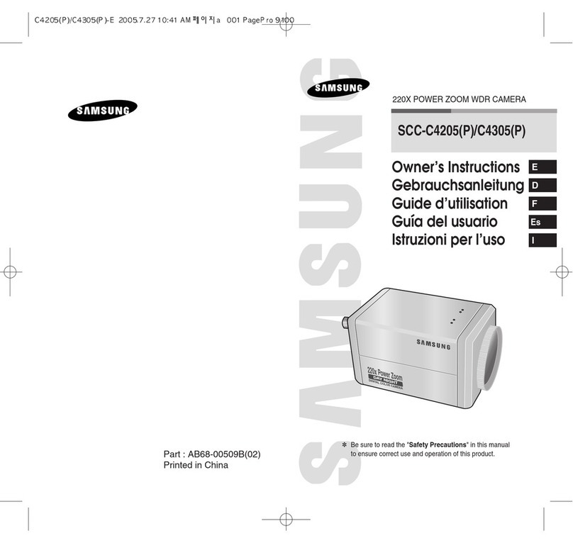
220X POWER ZOOM CAMERA
220x Power Zoom
LOW LIGHT
DIGITAL COLOR CAMERA
SCC-C4201(P , C4203(P ,
C4301(P , C4303(P
Owner’s Instructions
Gebrauchsanleitung
Guide d’utilisation
Guía del usuario
Istruzioni per l’uso
✽Be sure to read the Safety Precautions in this manual
to ensure correct use and operation of this product.
E
1
Safety Precautions
2
The purpose of safety precautions is to prevent
accidental injury or property damage. Always observe
all safety precautions.
✽
The precautions are divided into Warnings and
Cautions as distinguished below:
Warning
Ignoring this precaution
may result in death or
serious injury.
Caution
Ignoring this precaution
may result in injury or
damage to property.
4. Securely plug the power cord into the power
receptacle. (A loose connection may result in fire.)
5. When mounting the camera on a wall or ceiling,
fasten it safely and securely. (A falling camera may
cause personal injury.)
6. Do not place conductive objects (e.g.,
screwdrivers, coins, and metal things) or containers
filled with water on top of the camera. (Serious
injury may result from fire, electrical shock, or
falling objects.)
7. Do not install the unit in humid, dusty, or sooty
locations. (Doing so may cause fire or electrical
shock.)
8. If any unusual smells or smoke come from the unit,
stop using the product. In such case, immediately
disconnect the power source and contact the
service center. (Continued use in such a condition
may cause fire or electrical shock.)
9. If this product fails to operate normally, contact the
store of purchase or your nearest service center.
Never disassemble or modify this product in any
way. (Problems caused by unauthorized user
disassembly or repairs are not covered by your
warranty.)
10. When cleaning, do not spray water directly onto
parts of the product. (Doing so may cause fire or
electrical shock.) Gently wipe the surface with a dry
cloth. Never use detergents or chemical cleaners
on the product, as this may result in discoloration
of surface or cause damage to the finish.
Warnings
1. Be sure to use only the standard adapter which is
specified in the specification sheet. (page 28~31)
Using any other adapter could cause fire, electrical
shock, or damage to the product.
2. Check the external connection terminals first before
connecting the power source and signal wires.
Connect the alarm signal wires to the alarm
terminals. Connect the DC12V power adapter to
the SCC-C4201(P)/C4203(P) power input, making
sure that the currect polarity is observed.
Connect the DC12V or AC24V power adapter to
the SCC-C4301(P)/C4303(P) power input.
3. Do not connect multiple cameras to a single
adapter. (Exceeding the capacity may cause
abnormal heat generation or fire.)
E
3 4
Contents
Cautions
1. Do not drop objects on the product or apply strong
shock to it. Keep away from a location subject to
excessive vibration or magnetic interference.
2. Do not install in a location subject to high
temperature, low temperature, or high humidity.
(Doing so may cause fire or electrical shock.)
3. Avoid a location which is exposed to direct sunlight,
or near heat sources such as heaters or radiators.
(Neglecting to do so may result in a risk of fire.)
4. If you want to relocate the already installed product,
be sure to turn off the power before moving or
reinstalling it.
5. Install in a well-ventilated location.
6. Remove the power plug from the outlet when there
is a lightning storm. (Neglecting to do so may cause
fire or damage to the product.)
1. Overview.............................................................5
2. Part Names and Functions ...............................6
3. Installation........................................................ 8
Checking the Package Contents ....................... 8
Preparing the Cables ........................................ 9
Connecting the Cables .................................... 10
4. Navigating the Setup Menu........................... 12
Structure of the Setup Menu ........................... 12
- CAMERA ID................................................... 16
- IRIS................................................................ 17
- BLC................................................................ 17
- ALC ............................................................... 17
- MANU ............................................................ 18
- SHUTTER...................................................... 19
- AGC (MOTION) ............................................. 20
- WHITE BAL ................................................... 21
- SPECIAL ....................................................... 22
- AUTO FOCUS ............................................... 24
- MOTION DET ................................................ 24
- PRESET ........................................................ 25
- COLOR/ BW .................................................. 26
- EXIT............................................................... 28
5. Specifications ............................................... 29
6. Others ............................................................ 33
5
Overview
1
6
Part Names and Functions
2
E
This camera is a high performance surveillance camera that
provides a maximum of 220x zoom surveillance capability
with its 22x optical zoom lens and digital zoom IC.
It is a multifunction camera that is equipped with all of the
key features of the existing surveillance cameras :
●Day & Night function (SCC-C4203(P), C4303(P)) that
ensures sharp and clear images even at night.
●Low - Light Surveillance function that enables image
capture even under extremely low light conditions.
●White Balance function that provides accurate color
rendition under any light conditions.
●BLC function that enables effective back light
compensation even under a spotlight or a very bright
incident light.
●Auto Focus function that automatically tracks and focuses
on the moving subject.
●RS485/ Wired remote control function.
Broadcast System
●SCC-C4201/ C4203/ C4301/ C4303 : NTSC System
●SCC-C4201P/ C4203P/ C4301P/ C4303P : PAL System
Power System/Power Consumption
●SCC-C4201(P), C4203(P) : DC 12V/5.0W
●SCC-C4301(P), C4303(P) : AC 24V, DC 12V/5.5W
220x Power Zoom
LOW LIGHT
DIGITAL COLOR CAMERA
REMOTE RS-485 POWER
SET-UP button
The function of the SET-UP button varies depending on
whether you are currently in Normal Operation mode (i.e.,
the Setup Menu is not displayed) or Setup Menu mode.
☞In Normal Operation Mode
- UP/ DOWN buttons : Use as the ZOOM Tele button
and the ZOOM Wide button respectively.
- LEFT/ RIGHT buttons : Use as the FOCUS Near
button and the FOCUS Far button respectively.
- SET- UP button: Use to enter the Setup Menu.
Hold the SET- UP button for longer than 3 seconds to
enter the Setup Menu.
SET-UP button
Instead of “POWER”, “DC IN”
is writtern in
SCC-C4201(P)/4203(P).
Instead of “POWER”, “PWR
IN” and instead of “GND”,
“DC12&AC24V” is writtern in
SCC-C4301(P)/4303(P).
8
E
7
Installation
3
Checking the Package Contents
Make sure that the following accessories are included in
the package.
220x Power Zoom
LOW LIGHT
DIGITAL COLOR CAMERA
SCC-C4201(P),C4203(P),
C4301(P),C4303(P)
User's Guide
Before Installation
Mount Adapter
Screw (2)
Terminal Block
☞In Setup Menu Mode
- UP/ DOWN buttons: Use to move the cursor up or down.
- LEFT/ RIGHT buttons: Use to move the cursor left or
right, or to sequentially view the values that can be
assigned to a parameter.
- ENTER button: Use to select a Sub Menu item, and to
accept the current value.
ZOOM/ FOCUS REMOTE terminals
Use to control ZOOM/ FOCUS from an external controller.
Depending on the input conditions, the terminals can be
set to 4 different modes.
(Operating Voltage Range : +3V ~+13V, -3V~-13V)
ALARM OUT terminal
An alarm signal is output from this terminal when the
MOTION DET mode is activated or BW mode is activated.
(Open Collector
:
DC24V 40mA Max)
VIDEO OUT terminal
Connect the monitor's VIDEO IN. The video signal from
the camera is transmitted to the monitor via this terminal.
RS485 terminal
RS485 remote control terminal.
Power LED
Lights when power is on.
POWER IN terminal
Plug in the power adapter here.
Code Item
A
B
C
D
Tele
-6V
-6V
+6V
+6V
Wide
+6V
+6V
-6V
-6V
Far
+6V
-6V
+6V
-6V
Near
-6V
+6V
-6V
+6V
Caution : In the event of a simultaneous input of RS485 and
wired remote control signal, whichever was input first
will be activated.
(For a camera with the ROM version 1.2 or above,
please refer to page 33.)
910
E
1. Connect one end of the BNC cable to the VIDEO OUT.
2. Connect the other end of the BNC cable to the VIDEO IN
of the monitor.
3.
Plug in the power adapter. Use a minus screwdriver to
connect one part of the power adapter, which consists of two
lines, to the POWER terminal of the camera as follows :
REMOTE RS-485 POWER
REMOTE RS-485 POWER
Connecting the Cables
Video terminals on the back
of the monitor
BNC cable
POWER SELECTION switch
underneath the power adapte
POWER SELECTION
switch underneath the
power adapte
Preparing the Cables
To install and use the camera, first prepare the following
cables.
The requirements for the power adapter, which connects to
the camera's POWER IN terminal, are as follows:
●SCC-C4201(P), SCC-C4203(P) : DC12V 600mA
●SCC-C4301(P), SCC-C4303(P) : AC24V 300mA
DC12V 600mA
Video Cable
Use a BNC cable, such as the one shown below, to connect
the camera's VIDEO OUT to the monitor.
11 12
E
Navigating the Setup Menu
4
In this chapter, we will take a look at the menu system of the
SCC-C4201(P), C4203(P), C4301(P), and C4303(P). First,
we will take a look at the structure of the Setup Menu and
then describe the functions of each menu item in the menu.
●Structure of the Setup Menu of the SCC-C4201(P
Structure of the Setup Menu
CAMERA ID
IRIS
SHUTTER
AGC
WHITE BAL
SPECIAL
AUTO FOCUS
MOTION DET
PRESET
EXIT
OFF/ON...
ALC.../MANU...
OFF/1/100(1/120) ~ 1/10K
/AUTO X2~X128/FIX X2~X128
OFF/LOW/HIGH
MOTION S.S/SLOW/NORMAL/FAST/F.F
ATW/AWC/MANU...
...
CTRL TYPE A/B/C/D
LANGUAGE ENGLISH
RS-485 ...
PIP OFF/ON...
MIRROR OFF/ON
D-ZOOM OFF/X2 ~ X10
POSI/NEGA +/-
ZOOM SPEED 1/2/3/4
DETAIL(0) ---- I----
RET
AF/MF/ONEAF
OFF/ON...
...
QUIT/SAVE/PRESET
6. The requirements for RS485 control is as follows :
●Signaling Speed: 9600 bps
●Data Bit : 8 bits
●Stop Bit : 1 bit
●Parity Bit : none
SAMSUNG PROTOCOL
ADDR : 0
TYPE : RS-485, HALF
BAUD : 9600
LENS CHECK : OK!
4. Determine the type of power supply and set the POWER
SELECTION switch accordingly. Next, plug the power
adapter into a wall outlet.
The requirements for the power adapter for each model are
as follows:
●SCC-C4201(P), SCC-C4203(P) : DC12V 600mA
●SCC-C4301(P), SCC-C4303(P) : AC24V 300mA
DC12V 600mA
5. If the camera operates normally, the following screen will
be displayed for 5 seconds and then disappears.
13 14
E
Structure of the Setup Menu
●Structure of the Setup Menu of the SCC-C4301(P
CAMERA ID
IRIS
SHUTTER
AGC
WHITE BAL
SPECIAL
AUTO FOCUS
MOTION DET
PRESET
OFF/ON...
ALC.../MANU...
OFF/1/100(1/120) ~ 1/10K
/AUTO X2~X128/FIX X2~X128
OFF/LOW/HIGH
ATW/AWC/MANU...
...
V-SYNC INT/LINE...
LANGUAGE ENGLISH
CTRL TYPE A/B/C/D
RS-485 ...
PIP OFF/ON...
MIRROR OFF/ON
D-ZOOM OFF/X2 ~ X10
POSI/NEGA +/-
ZOOM SPEED 1/2/3/4
DETAIL(0) ----I----
RET
AF/MF/ONEAF
OFF/ON...
...
EXIT QUIT/SAVE/PRESET
MOTION S.S/SLOW/NORMAL/FAST/F.F
●Structure of the Setup Menu of the SCC-C4203(P
CAMERA ID
IRIS
SHUTTER
AGC
WHITE BAL
SPECIAL
AUTO FOCUS
MOTION DET
PRESET
COLOR/BW
OFF/ON...
ALC.../MANU...
OFF/1/100(1/120) ~ 1/10K
/AUTO X2~X128/FIX X2~X128
OFF/LOW/HIGH
ATW/AWC/MANU...
...
CTRL TYPE A/B/C/D
LANGUAGE ENGLISH
RS-485 ...
PIP OFF/ON...
MIRROR OFF/ON
D-ZOOM OFF/X2 ~ X10
POSI/NEGA +/-
ZOOM SPEED 1/2/3/4
DETAIL(0) ---- I----
RET
AF/MF/ONEAF
OFF/ON...
...
COLOR/BW/AUTO...
EXIT QUIT/SAVE/PRESET
MOTION S.S/SLOW/NORMAL/FAST/F.F
15 16
E
[SCC-C4201(P ,SCC-C4301(P ] [SCC-C4203(P ,SCC-C4303(P ]
The COLOR/BW option is available only with the
SCC-C4203(P) and C4303(P).
CAMERA ID
In the CAMERA ID menu, you can assign an ID to the camera
that appears on the monitor screen. If you select ON...
for CAMERA ID and press the ENTER button, a screen from
which you can assign a camera ID will appear.
You can use alphanumeric characters and a few special
characters that are displayed on the screen to assign a
maximum of 20 characters for the CAMERA ID.
You can use the LOCATION option to place the camera ID
anywhere on the screen.
(SET UP)
CAMERA ID OFF
IRIS ALC...
SHUTTER OFF
AGC LOW
WHITE BAL ATW
SPECIAL ...
AUTO FOCUS ONEAF
MOTION DET OFF
PRESET ...
EXIT QUIT
(SET UP)
CAMERA ID OFF
IRIS ALC...
SHUTTER OFF
AGC LOW
WHITE BAL ATW
SPECIAL ...
AUTO FOCUS ONEAF
MOTION DET OFF
PRESET ...
COLOR/BW COLOR
EXIT QUIT
(SET UP)
CAMERA ID ON...
IRIS ALC...
SHUTTER OFF
AGC LOW
WHITE BAL ATW
SPECIAL ...
AUTO FOCUS ONEAF
MOTION DET OFF
PRESET ...
COLOR/BW COLOR
EXIT QUIT
(CAMERA ID)
ABCDEFGH I JKL
MNOPQR S T U VWX
YZ0123456789
:!-+*()/
SP SP
LOCATION...
RET
ZOOM.CAMERA.........
Press the
ENTER
button.
●Structure of the Setup Menu of the SCC-C4303(P
CAMERA ID
IRIS
SHUTTER
AGC
WHITE BAL
SPECIAL
AUTO FOCUS
MOTION DET
PRESET
OFF/ON...
ALC.../MANU...
OFF/1/100(1/120) ~ 1/10K
/AUTO X2~X128/FIX X2~X128
OFF/LOW/HIGH
ATW/AWC/MANU...
...
V-SYNC INT/LINE...
LANGUAGE ENGLISH
CTRL TYPE A/B/C/D
RS-485 ...
PIP OFF/ON...
MIRROR OFF/ON
D-ZOOM OFF/X2 ~ X10
POSI/NEGA +/-
ZOOM SPEED 1/2/3/4
DETAIL(0) ----I----
RET
AF/MF/ONEAF
OFF/ON...
...
COLOR/BW COLOR/BW/AUTO...
EXIT QUIT/SAVE/PRESET
MOTION S.S/SLOW/NORMAL/FAST/F.F
Structure of the Setup Menu
17 18
E
If you set the AREA option to USER and press the ENTER
button, you can customize the area to which the BLC function
will be applied. You can specify the size of the area by using
the UP, DOWN, LEFT, and RIGHT buttons. After setting the
size of the area, press the ENTER button. The specified area
will start flashing. Then, you can use the UP, DOWN, LEFT
and RIGHT buttons to specify the location of the area.
Use the ENTER button and the UP, DOWN, LEFT and
RIGHT buttons to specify the size of the area and to position
the area. Press the ENTER button again to exit the AREA
setting menu.
MANU
If you select MANU for IRIS and press the ENTER button, a
screen from which you can manually adjust the iris to a
desired level will appear. In the LEVEL option, you can use
the LEFT/ RIGHT buttons to set the manual opening and
closing of the iris.
Press the
ENTER
button.
Use the UP,
DOWN,
LEFT, and
RIGHT
buttons.
(MANUAL)
LEVEL ( 00) ----I----
RET
(SET UP)
CAMERA ID OFF
IRIS MANU...
SHUTTER OFF
AGC LOW
WHITE BAL ATW
SPECIAL ...
AUTO FOCUS ONEAF
MOTION DET OFF
PRESET ...
COLOR/BW COLOR
EXIT QUIT
SIZE
POSITION
SIZE
POSITION
➞
➞
➞
➞
IRIS
The level of video output to the monitor can be controlled by
the iris lens according to the intensity of the incoming light.
This product is equipped with an iris lens. In the ALC (Auto
Light Compensation) menu, you can set the video output
level. In the MANU menu, you can manually set the opening
and closing of the iris.
BLC (Option in the ALC Menu)
If you use an ordinary camera when a strong light source,
such as a spot light, is shining from behind the subject, the
subject will appear dark on the monitor because of the back
light. For the SCC-C4201(P), C4203(P), C4301(P), and
C4303(P), appropriately set the BLC in the ALC menu to
solve the back -light problem and have a clear picture even
under a spotlight or a very bright incident light.
ALC
If you select ALC for IRIS and press the ENTER button, a
screen from which you can set the video output level and BLC
will appear. In the LEVEL option, you can use the LEFT/
RIGHT buttons to set the video output level. If you set the
BLC to ON, the BLC function will be applied to the screen
area specified in the AREA option. The AREA option can be
set to either PRESET or USER to specify the screen area to
which the BLC function will be applied. If you set the AREA
option to PRESET, the BLC function will be applied to the
area specified at the time of factory shipment.
(SET UP)
CAMERA ID OFF
IRIS ALC...
SHUTTER OFF
AGC LOW
WHITE BAL ATW
SPECIAL ...
AUTO FOCUS ONEAF
MOTION DET OFF
PRESET ...
COLOR/BW COLOR
EXIT QUIT
Press the
ENTER
button.
(ALC)
AREA PRESET...
BLC OFF
LEVEL ( 0) ----I----
RET