Heterence
Information
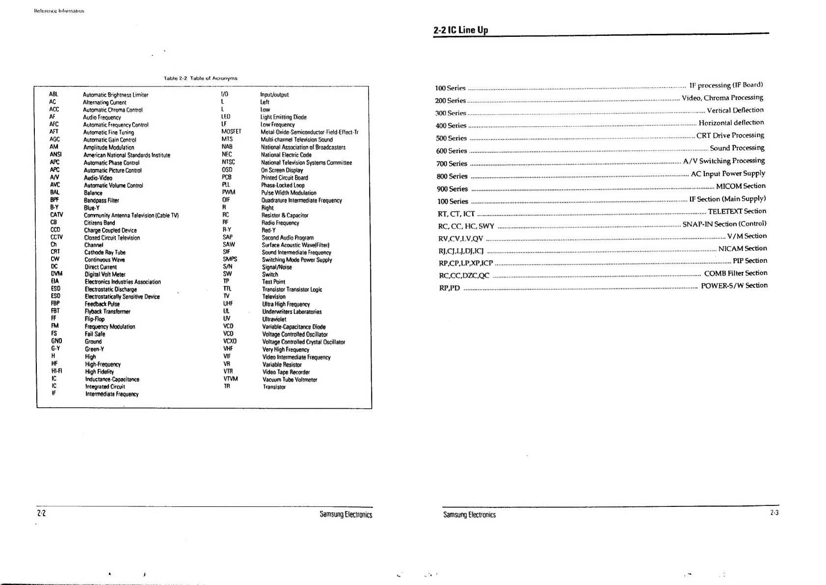
Table
2-2
Table
of
Acronyms
Automatic
Brightness
Limiter
70
Alternating
Current
L
Automatic
Chroma
Control
L
Audio
Frequency
LED
Automatic
Frequency
Control
LF
Automatic
Fine
Tuning
MOSFET
Automatic
Gain
Control
MIS
Amplitude
Modulation
NAB
American
National
Standards
Institute
NEC
Automatic
Phase
Control
NTSC
Automatic
Picture
Control
OsD
Audio-Video
PCB
Automatic
Volume
Control
PLL
Balance
PWM
Bandpass
Filter
OIF
Blue-Y
R
Community
Antenna
Television
(Cable
TV)
RC
Citizens
Band
RF
Charge
Coupted
Device
R-Y
Closed
Circuit
Television
Channet
Cathode
Ray
Tube
Continuous
Wave
Direct
Current
Digital
Volt
Meter
Electronics
Industries
Association
Etectrostatic
Discharge
Electrostatically
Sensitive
Device
Feedback
Pulse
Flyback
Transformer
Flip-Flop
Frequency
Modulation
Fail
Safe
Ground
Green-Y
High
High-Frequency
High
Fidelity
Inductance-Capacitance
Integrated
Circuit
Intermediate
Frequency
22
{input/output
left
Low
Light
Emitting
Diode
Low
Frequency
Metal-Oxide-Semiconductor-Field-Effect-Tr
Multi-channel
Tetevision
Sound
National
Association
of
Broadcasters
National
Electric
Code
Nationa!
Television
Systems
Committee
On
Screen
Display
Printed
Circuit
Board
Phase-Locked
Loop
Putse
Width
Modulation
Quadrature
Intermediate
Frequency
Right
Resistor
&
Capacitor
Radio
Frequency
Red-Y
Second
Audio
Program
Surface
Acoustic
Wavelfilter)
Sound
intermediate
Frequency
Switching
Mode
Power
Supply
Signal/Noise
Switch
Test
Point
Transistor Transistor
Logic
Television
Ultra
High
Frequency
Underwriters
Laboratories
Ultraviolet
Variable-Capacitance
Diode
Voltage
Controfied
Oscillator
Voltage
Controlled
Crystal
Oscillator
Very
High
Frequency
Video
Intermediate
Frequency
Variable
Resistor
Video
Tape
Recorder
Vacuum
Tube
Voltmeter
Transistor
Samsung
Electronics
2-2
1C
Line
Up
SS
JOO
Series
coecccecceccssescsscsecscseesesesecseecesecnsacenssesesesanseesessseeneneqecneterevsrsisenensrsstisesemeeretennrarearastes
IF
processing
(IF
Board)
200
Series
.....scccescscsssscsessssesessnssesesecerescsesseseeaesesssaesacseaeseesassecessasscescaeaveseeravennansacersessnsereeses
Video,
Chroma
Processing
BOO
Series
o.ccccecccseceessesesecsesesesscseseeseenescesceceueeeensaesieitenenersimsseaceecseanseesans
addarrseestetieeehie
ss
Vertical
Deflection
400
Series
oo.
cccecessecsssecsscesseesssececeveneescnsevesecseseanenssesnensacnnacsucssneensacanenanenncaaes
...
Horizontal
deflection
SOO
Series
ooececsssccesesseecsesesssessesseconseseneesesscensssesacssssnersanececnessersessesnesseesssesesseesstassnenavenaesctaneaeeess
CRT
Drive
Processing
600
Series
o..ceeccccsccsssesssessessecneestcnveneensssesstsaneseesessssaeanssesesonsevenaesneersaucaensaneancqneesanecnisancareeratesestecaeesstss
Sound
Processing
JOO
Series
..cscecssssesseessecseeeeeeesessrsneescsscsacsseesesseanensessenscssenssenssscaresnseacaneneenseneenecgtenagerensnents
A/V
Switching
Processing
BOO
Series
oovceeccescsesssssssccsecesecceeesuceneecsscsnsscsessesesecneesecsnessseussasecanecaesaveesecssessseasseneeanensenareastenes
AC
Input
Power
Supply
QOO
Series
coeccsssscsscsesseessecssessncesncsessescccssceveeneesessessessassnsssssnecsscssuecueesucsnrasecesosessasssnecananseeseennennesseeasennes
MICOM
Section
WOO
Series
...ceccsecccsssscseesssecsseesssessnscsssssssuessanecnssessessacesnsessesansecunessansessosessnnecsaseesnserensgnanstensy
IF
Section
(Main
Supply)
RT,
CT,
ICT
eessecsessssesssesescoucssssconesuceveeseesstssscasvecncsussnseneeaccnsecanecuseanecuessnesosesneanecanesssenecsanseaseaeeansnnees
TELETEXT
Section
RC,
CO,
HC,
SWY
cesesssssssscssessesceresseesessnssscesssvseseasensesaneenecanetaeccnceunssuecsscanssavanseenscoassens
SNAP-IN
Section
(Control)
RV,
CV,
LV
OV.
eecssesssesssscsnessecsssesneessccasssseenuessssuesscanscarsneessessneenscanecananussncsneasenssscavecnnensscevenveenseaenaarasnne
tine
V/M
Section
RY
CI
LJ
DY
ACI
oesseseessssessssssccsessesesnscsessssenesnsecssnsccsnscssnsesnasscsssusesssersenssceenncassncereeneetensansnrcssicasiansaseses
NICAM
Section
RP,CP,LP,XPACP
...ceessesssscseeecsessesessscuscsesssvcsscsecersceusencescssucsusenscanscascenensccassssensecsnecnscesesassensransnsenecnoganens
ness
PIP
Section
RCE,CO,DZC,QC
creeccsecssssssscsesnnessessnessesssensnsesesssecsscaneseensssnessncansssnsnsanvecersencenscanacanerncsaveqnesancnnets
COMB
Filter
Section
RP,PD
oocccsseccsssescsseessesensesesseccsscsscssssssssessssessvecsnecescceseeasesnanersnsssavonevecencesnensnasaressansennenonsetnrteaee
POWER-S/W
Section
i
Samsung
Electronics
2:3