Samsung WF520ABP/XAA User manual

# tsWF520 RevB 03/21/2011 1
Fast Track Troubleshooting
Model:
WF520ABP/XAA
WF520ABW/XAA
Publication # tsWF520 Revision Date 03/21/2011
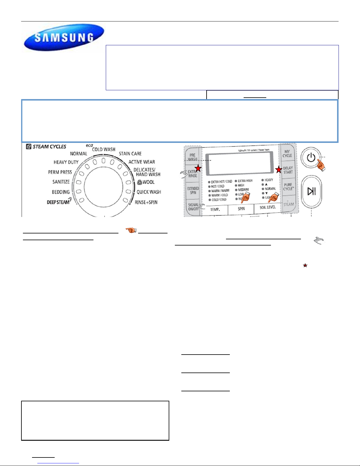
Quick Test Mode
To enter press Spin, Soil, & Power simultane-
ously with the power off.
1. All LED’s light up and the washer beeps as it
enters the Quick Test Mode.
2. After the displaying the software version, LCD
will display Model information. If EEEE is displayed
the PCB ass’y is defective.
4. When the version is displayed, turn the Jog-Dial
CCW so that the version disappears. Press the fol-
lowing keys to test the various components:
Press Temp Key to cycle through the Water Valves
circuit test (lock the door first) in this order: Pre-Wash,
Bleach, Cold Main, Hot, & Steam, then off.
Press Spin Key to test Door Lock/Unlock circuit
Press Steam Level Key to test Circulation/Drain Pump.
Press Soil Key to test the Water/Steam Heater.
When either Test or Spin is displayed on the LCD,
press Start/Pause key to conduct the motor test.
In Test mode, you can test the clockwise and counter-
clockwise movement of the motor. In Spin mode, you
can test the motor at a high rpm.
Service Mode:
This mode allows more detailed operation tests and trouble-
shooting, to enter press Signal & Extra Rinse
simultaneously with the power on.
While in Service Mode the following tests can be performed:
Quick Spin Test = Delay Start & Extra Rinse: This accel-
erates the drum motor from 0 to maximum RPM over a few
minutes. Note: Stay with the washer during this test, out of
balance detection may be bypassed. Press the Start/Pause
button during the test to hold its spinning speed for 10 minutes
before going back to Quick Spin Test Mode. Press and hold the
Delay Start & Extra Rinse button to continue.
Cycle Count = Press Signal button to see # of times used.
Soft Ware # = Press Soil button to see software version info.
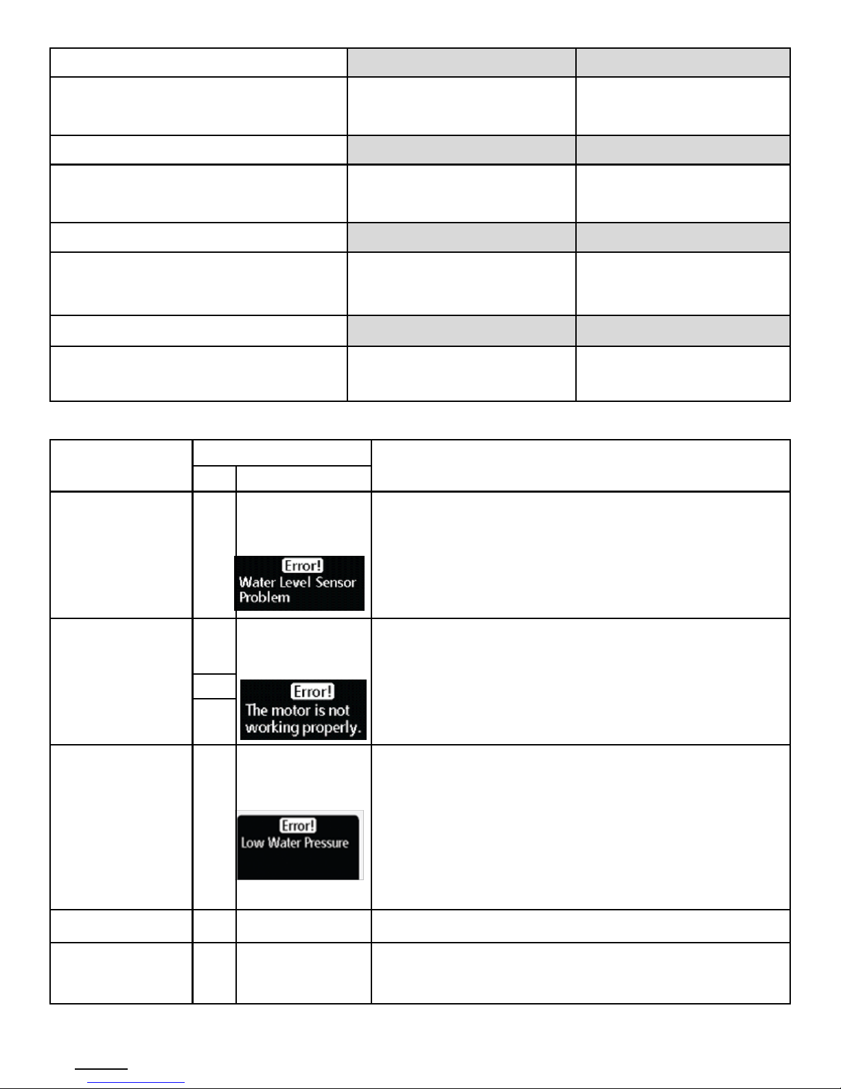
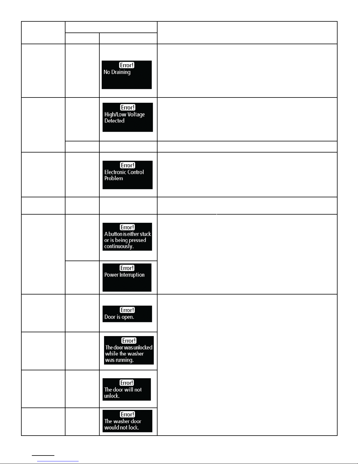
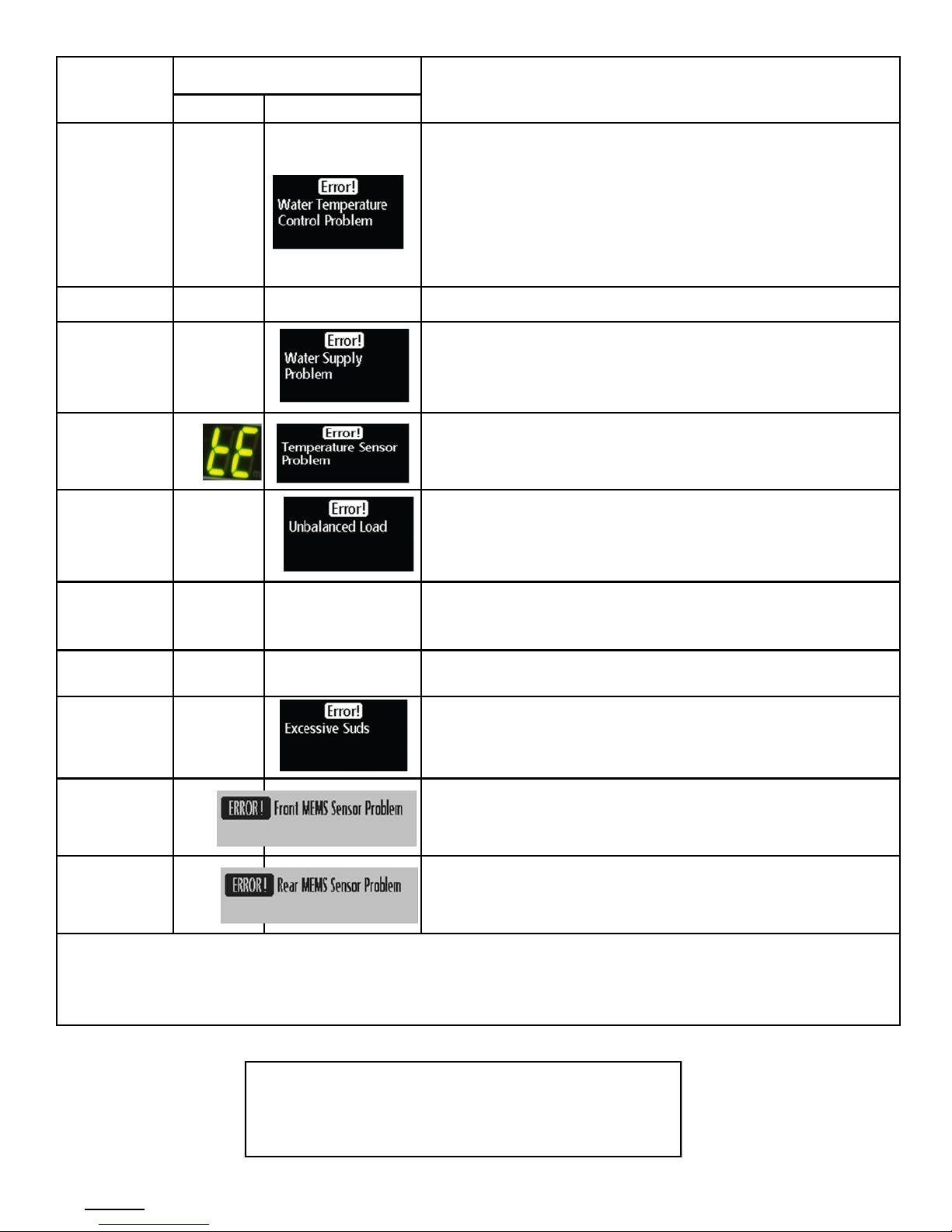
Fault Code Test = Press the Spin button to view the stored fault
codes –then turn Jog Dial to view error codes (Push Start/
Pause while the code is displayed to view the number of cycles
since the error occurred, Push Start/Pause to go back to faults)
Peripheral (Main PCB) input Tests
1. Select Extra Wash. Then turn the Jog-Dial so that the Heavy
Duty LED is turned on. Next, press the Start/Pause Key. The
Water Temperature will be displayed in Fahrenheit.
2. Select Extra Wash. Then turn the Jog-Dial so that the Perma-
nent Press LED is turned on. The door status will be displayed
(OP if open, CL if closed).
3. Select Extra Wash. Then turn the Jog-Dial so that the Sani-
tize LED is turned on. The door lock Switch status will be dis-
played (UL if unlocked, Lo if locked).
4. Water Frequency/Water Sensor Testing - Select a cycle &
start the washer, enter Service Mode & press Extra Wash.
Turn the Dial so that the Bedding LED is turned on. Next, press
the Start/Pause Key. The Water Frequency will be displayed.
The frequency will change as the unit fills.
IMPORTANT SAFETY NOTICE –“For Technicians Only” This service data sheet is
intended for use by persons having electrical, electronic, and mechanical experience
and knowledge at a level generally considered acceptable in the appliance repair trade.
Any attempt to repair a major appliance may result in personal injury and property
damage. The manufacturer or seller cannot be responsible, nor assume any liability for
injury or damage of any kind arising from the use of this data sheet.
EEPROM Clear Check
Power off, Press Delay Start, Signal and Power Key at
the same time. Good = Good Fail = FAiL
All memory will be cleared, including Fault Codes
This should be done when a new Main PCB is installed
SUPPORT INFORMATION
Training —Plus One http://my.plus1solutions.net/clientPortals/samsung/
Help —GSPN http://service.samsungportal.com/
Samsung Product Support TV http://support-us.samsung.com/spstv/howto.jsp
Customer information videos and chat programs. Programs for Fridges, Laundry, Ranges & D/W

# tsWF520 RevB 03/21/2011 2
CN8 CN7 CN6
CN10
CN1
CN3
CN6
CN2
RY1
RY11 RY13
To MEMS
connector
on Main
PCB CN11
To MEMS
connector
on outer
tub
CN11
PNK
BLU
YEL
RED
VIO
WHT
ORG
Door Ck Sw
Thermistor
CN7

# tsWF520 RevB 03/21/2011 3
Washer Connector Checks WF520
CN1
1 Door Lock Close (Blk)
2 Door Lock Open (Wht)
3 Drain Pump (Vio)
4 Steam Valve (Brn)
5 Bleach Valve (Pnk)
6 Bubble Pump (Gry)
7 Pre Valve (Yel)
8 Main Valve (Blu)
9 Hot Valve (Red)
CN6
1 AC Pwr (L1) (Blk)
2 Door Lock Detection (Gry)
CN7
1 Reactor Connector Port (Red)
2 Reactor Connector Port (Red)
RY11 Steam Htr Relay
1 Heater (Wht)
2 L1 (Blk)
RY1 Power Relay
1 (Blu)
2 (Wht)
RY13 Washer Htr Relay
1 L1 (Blk)
2 Heater (Red)
CN8
1 Motor Pwr U Phase (Red)
2 Motor Pwr V Phase (Wht)
3 Motor Pwr W Phase (Blu)
CN3 (Hall Sensor)
1 +5 vdc (Pnk)
2 Sensor Signal (Red)
3 Sensor Signal (Blu)
4 Ground (Org)
CN11 Mems Boards
1 3.3vdc (Red)
2 Chip Select 1 (Yel)
3 Chip Select 2 (Vio)
4 Output Signal (Blu)
5 Input Signal (Wht)
6 Clock Signal (Pnk)
7 DC Common (Org)
CN10
1 Tx Disp pcb(Vio)CN7 2 Rx Disp pcb(S/Blu)CN7
3 Reset Signal Disp(Pnk)CN7 4 5vdc (Brn) CN7
5 DC Common (Org) CN7 6 15vdc (Blk)
7 Main Reset (Yel) 8 Water Level (Blu)
9 Watchdog Signal (Wht)
Steam Heater Relay Check Test 1 Test 2
Connector CN6 Pin 2 (Gray) and RY11 (heater re-
lay) Pin 1 (White)
120VAC with the Heater On and 0VAC
with the Heater off
Power Off, heater resistance is
15.6 Ω
Heater Relay Check Test 1 Test 2
Connector CN6 Pin 2 (Gray) and RY13 (heater re-
lay) Pin 2 (Red)
120VAC with the Heater On and 0VAC
with the Heater off
Power Off, heater resistance is
16.6 Ω
Hall Sensor Check Test 1 Test 2
Connector CN3 Pin 4 (Orange) and Pin 2 (Red) ad-
ditionally Pin 4 (Orange) and Pin 3 (blue)
Manually spin the drum to see the volt-
age change, Power On
N/A
0Vdc or 3.75Vdc
Motor Check Test 1 Test 2
Connector CN8 Pin 1 (Red), Pin 2 (White) and Pin 3
(Blue)
Power Off 11.5Ω across Pins 1-2, Pins 1
-3, & Pins 2-3
N/A
A/C Power Check Test 1 Test 2
Connector CN 6 Pin 1 (Black) and RY1 Pin 1 (Blu) Power On 120VAC N/A

# tsWF520 RevB 03/21/2011 4
Door Lock Check Test 1 Test 2
Connector CN6 Pin 2 (Gray) and CN1 Pin 1 (Black) When Door is Locked or Unlocked
there is a pulse of 120VAC for a few
milliseconds.
With Power Off, the resistance
between CN1 Pin 1 (Blk) and Power
Relay pin 2 (Blu) will be between
47 - 57Ω
Door Unlock Check Test 1 Test 2
Connector CN6 Pin 2 (Gray) and CN1 Pin 2
(White)
When Door is Locked or Unlocked
there is a pulse of 120VAC for a few
milliseconds.
With Power Off, the resistance
between CN1 Pin 2 (Wht) and
Power Relay pin 2 (Blu) will be be-
tween 47 - 57Ω
Drain Motor Check Test 1 Test 2
Connector CN1 Pin 3 (Vio) and RY1 Pin 1 (Blu) 120VAC with the pump On and 0VAC
with the pump off
With Power Off, the resistance
between CN1 Pin 3 (Vio) and
Power Relay pin 2 (Blu) should be
13.9Ω
Water Valve Check Test 1 Test 2
Connector CN6 Pin 2 (Gray) to CN1 Pin 5 (Pink),
Pin 4 (Brown) , Pin 7 (Yellow), Pin 8 (Blue), Pin 9
(Red)
120VAC with the Valve On and 0VAC
with the Valve off
Power Off, valve resistance is from
1202Ω - 1245Ω
Error Type Error Mode Details
LED LCD
Water Level Sensor
LE
8
Check the Hose where the sensor is connected, may be loose,
pinched, damaged or clogged. Also check the sensor it may be
disconnected or defective. The Main PCB may also be defective
Motor Drive Error or
Hall Sensor error
3E
Check the motor drive connector, it may be loose. The hall sensor
may be disconnected, loose or damaged . Check for a foreign ob-
ject inside the motor or motor damage. The stator might be loose
or damaged. The drum might be overloaded from too many clothes
or the relay or PCB might be defective.
E3
bE
25
Water Supply
Error
nF
3
Check the water valve wiring harness.
Check whether the water supply valve is clogged with foreign ma-
terial and whether water is supplied properly.
Check for reversed fill hoses
Check water temperature, if sensed as higher than 50 ˚C in the
Wool or Lingerie cycle it will create error.
Check the relays, if they operate correctly replace the Main PCB.
Fill Hoses Reversed nF1 Correct Hot/Cold hose connections
System Error SF1
SF2
SF3
Replace PCB

# tsWF520 RevB 03/21/2011 5
Error Type Error Mode Details
LED LCD
Drain Error
nD
1
Check for Foreign material entering the pump or hoses.
Check to make sure the wiring harness is connected properly.
Check the water pump terminal .
Check for freezing
Power Error
2E
91
92
Make sure to check the operating voltage. (An error occurs when
under or over voltage is supplied.) Check whether a plug recepta-
cle is used. When the connecting wires are too small (extension
cord use), a momentary low voltage may drop up to 10 V
Main PBA fault (sometimes)
PF Momentary Power Failure
Communica-
tion Error
AE Check the wire connections and terminal contacts between the sub
and main PBAs.
Check for disconnected wires.
Check whether the sub PCB is short circuited because of moisture.
If the main PCB’s communication circuit is faulty, replace it.
EEPROM
Fault.
11 Go to ―EEPROM Clear Mode‖ If display shows ―FAiL‖, Replace Ma-
chine Control Board
Switch Error
(Main Relay
Error)
E2
15
Check whether either the Power switch or a tact switch (any button)
is stuck down.
Check whether the service PBA holding screws are fastened too
tight pinching the contacts
If the main PBA switching IC on/off error has occurred, replace the
main PBA.
The ―E2‖ error occurs if the main relay connections are incorrect.
Check the connections. If there is no error in the connections, re-
place the main PBA
SR
dS
22
(Before
operation)
Check the door switch and latch alignment .
Check the latch for damage
Check the wiring harness to the latch.
Check the door switch. Replace if faulty.
Check the main PBA door sensing circuit. Replace if faulty.
Finally verify he operation of the Main PCB
Door Error dL
18
(During
operation)
LO
2
(Unlock
Fail)
FL
4
(Lock Fail)

# tsWF520 RevB 03/21/2011 6
Laundry Touch Up Paints
TOUCH UP PAINT, BLUE ONYX DH81-11980A
TOUCH UP PAINT, IMPERIAL SILVER DH81-11981A
TOUCH UP PAINT, NEAT WHITE DH81-11982A
TOUCH UP PAINT, STRATUS GRAY DH81-11983A
TOUCH UP PAINT, TANGO RED DH81-11984A
Error Type Error Mode Details
LED LCD
Heater Error
Hr
36
(Heater
Relay)
This can be a short or a wire disconnected to the heater circuit. This
can also be problem with the tub contacting the heater or if the wa-
ter in the tub is frozen or there is no water. The error is triggered by
temperatures above 145C. If the heater has no error, this occurs
because of a PBA relay malfunction. Check the wiring harness to
the heater.
An Hr error occurs if the steam heater, is faulty, replace it.
9E1 EMC Filter issue or a noise spike from an external device
Overflow error
OE
1E
Water is supplied continually because the water level detection
does not work. - Verify the drain is working properly, the water level
detection does not work and water is supplied continually. Verify the
water valves shut off fully. Finally check the water level sensor.
Temperature
Sensor Error
29 The washing heater temperature sensor in the tub has an error.
Check the connections for the washing heater temperature sensor
connector.
Unbalance
Error
dC
10
Check the type of laundry. Check whether it may cause an unbal-
anced situation.- Educate the consumer in this case, to press
pause, reposition the load or remove a few items. Press start to
continue and complete the wash cycle.
Silver Care Kit
(Silver Care
PCB) Failure.
7E Check Silver Care PCB ,Main PCB & Wire-harness
Mems or Har-
ness Failure
8E Check MEMS PCB ,Main PCB & Wire-harness
Foaming
Detected
SUdS
Sd
This occurs when too much foaming is detected. It is also displayed
while foaming is removed. When the removal is finished, the normal
cycle proceeds. (This is one of the normal operations. It is an error
for preventing non-sensing faults.)
8E1 Front MEMS Sensor problem: Restart the cycle
If the error continues,
Replace Mems sensor
8E2 Rear MEMS Sensor problem: Restart the cycle
If the error continues,
Replace Mems sensor
Check whether the washing machine is level to the floor with respect to the original position of the washing machine prior
to service. Doing this now will reduce the need for a redo call and customer dissatisfaction.
✔ Vibrations can shorten the lifetime of the product.

# tsWF520 RevB 03/21/2011 7
Pre Wash
Main Wash Softener
Bleach
Path #2
Path #1
Path #3
Path #4
Path #5
V#1 V#2 V#3 V#4 V#5
MAIN(H) PRE WASH BLEACH MAIN(C) STEAM
Water valve connections for the Detergent Drawer
When installing a washer and dryer on
the first, or second floor, do not exceed
this leg adjustment height for stability.
Stacking Kit : (Model No : SK-5A/XAA)
Samsung washers and dryers can be stacked to maximize usable space.
An optional stacking kit is available for purchase from your Samsung retailer
Items Packed With Washer
BOLT-SPANER (10-13mm Wrench) DC60-40146A
ASSY HOSE WATER HOT DC97-15648B
ASSY HOSE WATER COLD DC97-15648A
MANUAL-BOOK DC68-02838A
CAP-FIXER DC67-00307A
HOSE-HANGER DC62-10278A
When using non-HE
detergents, or using
too much detergent
for the water hard-
ness and soil level of
the clothing, over
sudsing will occur.
When this happens
there will be leaks out
of the detergent
drawer and door.
Please advise con-
sumer of proper de-
tergent usage.
It is normal for a small amount of water
remaining in Detergent Drawer after it
completes washing. Bleach is usually
flushed out into the tub at the beginning
of the washing. Also, its compartment is
washed again during the following rinse
cycle, removing any remnants.
Location considerations
Do not install your washer
in areas where water
may freeze, since your
washer will always main-
tain some water in its wa-
ter valve, pump, and hose
areas. This can cause
damage the belts, the
pump, hoses and other
components. Operating
temperature should be
above 60°F/16°C.
This manual suits for next models
1
Table of contents
Other Samsung Washer Dryer manuals
Popular Washer Dryer manuals by other brands

montpellier
montpellier MWDI7555 Installation and operating instructions

Maytag
Maytag MLE20PDAYW installation instructions

Beko
Beko HTV 7716 DSW BT user manual

Bosch
Bosch WFT2806GB Instruction manual and installation instructions

Frigidaire
Frigidaire GLET1142CS0 installation instructions

Indesit
Indesit IWDE 7125 S Instructions for use