SAMUEL JACKSON HO-4-1118 User manual

01
L-
FI
R
ED
H
EATERS
EO-4-1118
AND
HO-
7-1
11
4A
\SAMUEL
JACKSON
DRYAIRE HEATER

17400
TEMPERATURE
CONTROL
ASSEMBLY
OPERATION
NOTES
This assembly incorporatesUDC
3000
digitaltemperature controllers. To keep controloutputsfrom
increasingduring the preburn routine, they take their power from the flame signal.
If
the heateris
equippedwith
the
16910 ModulatingHighTemperature Limit to controltemperaturebeforethe mix
point,there
will
be
two
digital controllers(one on the left and one on the right). If the 16910 isnot
used, there
will
beasinglecontrollermountedon the left. The same assembly isusedon all heaters,
whether they have relayor microprocessorcombustioncontrols.
This assembly hastwoindicatorlights, STATUS and FLAME. Their operationisas follows:
STATUS LIGHT
--
When used with
the
HG-3-1110heater, this light will be
ON
duringpreburnroutine
and operation.
On all other heaters, which have microprocessorcombustioncontrols, this light will be
ON
while in
operationand preburn and OFF during postburnroutine.
It
will
indicatealarm and error conditions
byblinkingas explainedbelow.
FLAME LIGHT
--
With allheaters, this lightwill be
ON
when flame isestablished.
ALARMSAND ERRORS
ALARMS
--
Problems notseriousenough toshut downoperation.
ERRORS
--
Problems which requirethat operationscease.
ALARM PROCEDURE
--
Duringoperation, the STATUS light will blink at the rate of one pulse every
twosecondsfor
5
minutesthen revertto
ON.
Duringthe 5-minuteinterval, the ALARM light on the
local
panel will
be
ON.
The counter will display the code number corresponding to the alarm
problem,and
will
resetto zero at theend of the interval.
ERROR PROCEDURE
--
The burner will shut downand cannotberestartedunlessthe RESET button
on the localpanelispushed. The counter
will
displaythe appropriatecode number and the ALARM
lightwill
be
ON
until
the
RESET
button
is pushed. The STATUS light will blink at the rate of one
pulse per second for
5
minutes, then go
OFF.
If
an attempt is made to start the burner before
RESET, theSTATUS lightwill blinkfor 10
seconds
thengo OFF.
17400
901108

USING
THE
17400
DIGITAL
TIEMPEBATURl3
CONTROL
(WITHTHE
16910
MODULATING HIGH TEMPERATURELIMIT)
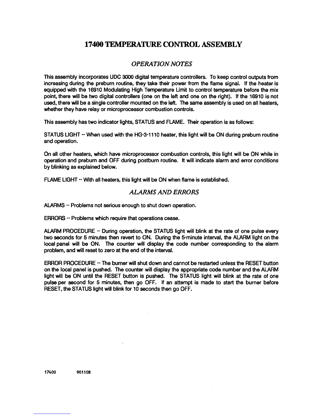
The
17400
Temperature Control Assembly for Samuel Jackson Dryaire Heaters can be used with the
16910
ModulatingHighTemperature Limitto preventhightemperatureswhich canharm cottonqualityand, inextreme
cases, cause fires. These instructionswill provideoperating guidelinesfor use of this control arrangementwith
allSamuelJacksonDryaireHeaters.
PRINCIPLE
OF
OPERATION
The
17400
control assemblyuses two HoneywellUDC-3000digitaltemperaturecontrollers. The controlleron
the
!&
as you face the controlassembly is designatedthe "PRIMARY controller. The controller on the
riaht
is
designatedthe "HIGH LIMIT" controller. The PRIMARY controller has its thermocouple temperature sensor
mountedDOWNSTREAMof the mixpointinthe drying system. The MIGH LIMITcontroller has itsthermocouple
mountedupstream of the mixpoint. The PRIMARY controller watches the temperature after cotton has mixed
withthe air.
If
wet cotton isfed intothe system, the air iscooled and the PRIMARY controllersignalsthe HIGH
LIMITcontroller that more heat is needed to compensatefor this cooling. The HIGH LIMIT controller operates
the burner's gas valve to supply this heat, but in no case will the temperature be permittedto exceedthe limit
whichthe ginner has previouslyspecified. If drycottonisfed intothe systemthe reverse occurs. Inthe case of
achoke
or
large air leak, the HIGH LIMIT controller may not be able to contain the temperature within the
specifiedlimits and
it
will then shut down the burner to prevent a fire (with an appropriate ERROR code
on
burnerswith microprocessorcombustioncontrols).
NORM& OPERATIONPROCEDURE
There isaspring returnselector switchlocatedbelowthe PRIMARYcontrollerwith a
"1"
on the rightand a
"0"
on
the
left.
These are symbolsfor START-STOPoperations. Turnthe switchto
"1"
andrelease itto start the burner.
Turnthe switchto
"0"
to shut downthe burner. After turningthe switchto
"l",
pleasenotethat there isa preset
time delay to allowthe burner head and pipingto be purgedwith air. Followingthis delay, ignitionis triedand
shouldoccur immediately.
If
ignition is not successful and your model has microprocessor combustion
controls, observe the STATUS lightto see
if
it isflashing. If
it
is, go to the burner'scontrolcabinetand notethe
ERROR/AIARM code displayed on the localpanel. There is a decal at the controlcabinet and a page in each
servicemanual explainingthe numbers. It will be necessaryto pressthe RESET button on the burner's local
panelin orderto clearthe
ERROR
andrestartthe burner. Inthe case of failure inignition
or
failure inoperation,
the burner will automatically attempt to restart itself for a maximum of three attempts. Neither digital
temperaturecontroller will come on untilflame has beenestablishedinthe burner. This isto preventthe highly
responsivecontrolsfrom "windingup"duringthe air purgedelaytime and causingthe burner to come on with a
roar. When they do energize, the controllers will take
12
seconds to perform self-check operationsand then
displaythetemperatures.
There are four temperatures displayed at all times during burner operation. The PRIMARY control on the
left
shows twoandthe HIGH LIMITcontrolon the rightshowstwoas well. The lowerdisplayonthe PRIMARYisthe
temperaturewhich the ginner sets and is the only one he will adjust under normal circumstances. It isthe
temperaturedesired after the mixpoint. It is raisedand loweredwith the orange buttons below it. The upper
displayshows the actual temperature being reported by the downstreamthermocouple. On the HIGH LIMIT
controller,the lower display is the temperature which the PRIMARY control is feeding it (See "Principle
of
Operation"Section). The upperdisplayon the rightisthe actualtemperaturebeforethe mixpoint. By observing
the upper display on both controllers,it is possibleto estimate the wetness of the incoming cotton as they
will
movefarther apart asthe cottongets wetter.
Page
1

17400 CONTROLWITH 16910 HIGHLIMIT 11
/90
17600
CONTROLINTERFACE
OPTION
When the 17400 controlisusedwiththe 17600 Control InterfaceOption,
it
isnot necessaryfor the ginner to use
the arrow buttonson the PRIMARY controllerto adjust the desiredtemperaturedownstream. The PRIMARY
will
obtainthis value from the 17600 (whichiscoming from a GranberrySeries
800
Moisture Monitor).
If
the ginner
disagreeswith the suggested temperature coming from the 17600, he should use the arrow buttons on the
17600to adjust
it
to his preference. Pressing the DOWN ARROW buttonon the 17600tells the control that he
desiresa lower cotton moisture content at the feeder apron and it will turn UP the temperature on the 17400
controlto achieveit. Pressingthe UP ARROW buttonworks inreversetothis.
If
it isever desiredto bypassthe Series
800
andthe 17600 Control Interface,operatingthe burner with manual
setpointentry by the ginner can be done easily. Remove the button cover on the upper left button on the
PRIMARYcontrol. This isthe FUNC button. Pressingthis buttonwill tell the PRIMARY controller to ignorethe
incomingsignal from the 17600 (designated
"RSP
on the lower display) and take its temperaturecommands
from the ginner. The new lower display will be designated "SP".
"RSP
stands for Remote Set Point and "SP"
standsfor Set Point.
ADJUSTING THEMODULATING LIMIT
The modulating limit is the temperature before the mixpoint which the control is programed not to exceed.
Please note that the burner will not be killed,
it
will simply not be allowedto go over this setting. This setting is
factorypreset at
350
F (176 C) as there is general agreement in the industrythat temperaturesinexcessof this
levelpermanentlydamage cottonfibers. The procedurefor changingthissettingfollows.
The programmingis done on the HIGH LIMIT controller. Remove the button covers on the lefthandtop and
bottombuttons. These are labelled FUNC and SETUP. First, unlock the controller by pressingSETUP 1time
and FUNC 4 times. LOCKOUT shouldbe displayed in the lower display. Press either ARROW button untilthe
upperdisplaysays NONE. Press LOWR DISP one timeto unlockthe control.
Now pressSETUP
5
times until INPUT2 isdisplayedinthe lowerdisplayarea. Press FUNC 2times untilIN2
HI
isinthe lowerdisplay. This isyour modulatinghighlimitvalue. Use the ARROW buttonsto set itat the desired
level. Please note that the controller will not operate correctlyif this value is set higher than 400 F (204 C)
or
lowerthan 200
F
(93 C). PressLOWR DlSPto set the newvalue.
Relockthe control by repeatingthe above procedurebut pressingthe ARROW buttonsuntil MAX LOCKOUT is
displayed. Replacethe buttoncoverstodiscourageuse byunauthorizedpersonnel.
ADJUSTING THE
CUTOFF
SAFETY
LIMIT
This limit is set on the HIGH LIMIT controller in a similar fashion to the modulating limit. Remove the button
coverson the lefthand top and bottom buttons. These are labelled FUNC and SETUP. First, unlock the
controllerby pressingSETUP one time and FUNC 4times. LOCKOUTshouldbedisplayedinthe lower display.
Presseither ARROW button until the upper display says NONE. Press
LOWR
DlSP one time to unlockthe
control.
Now press SETUP
8
times untilALARMS is displayed in the lower displayarea. Press FUNC 1time untilAlSl
VAL is inthe lower display. This is your cutoff high limitvalue. Use the ARROW buttonsto set it at the desired
level. We recommend setting this value approximately 25-50 degrees
F
above the modulating limit. Press
LOWR DlSPto set the newvalue.
Relock the control by repeatingthe above procedurebut pressingthe ARROW buttonsuntil LOCKOUT MAX is
displayed. Replacethe buttoncoversto discourageuse byunauthorizedpersonnel.
17400-H
1
I
Page2

3550
5-91
HO-4-1118 AND HO-7-1114A OIL-FIRED HEATERS
WITH
16910
HIGH TEMPERATURE LIMIT
STUB-UPS
-
NO. DESCRIPTION
1
BURNER POWER
BURNER TEMPERATURE CONTROL
THERMOCOUPLES
PRIMARY
HIGH LIMIT
FUEL OIL SUPPLY FOR BURNER
FOR DUAL-FUEL VERSIONS ONLY:
BURNER
GAS
SUPPLY
ROUTING AND NOTES
FROM ELECTRIC SERVICE TO BURNER
3
WIRES 380 V
50
HZ OR
3
WIRES 415 V
50
HZ OR
3
WIRES 480 V
60
HZ
6
HP
4.5
KW
MOTOR STARTERS AND 120 V CONTROL
TRANSFORMER ARE IN BURNER CABINET
FROM BURNER CABINET TO
TEMPERATURE CONTROL AT CONSOLE
9
-
16
GA WIRES
FROM CONSOLE TO ENTRANCE OF
TOWER OR EXIT OF FOUNTAIN AND
TO HOT AIR BEFORE MIX POINT
2
PAIRS TYPE-J THERMOCOUPLE WIRE.
DO
NOT RUN WITH A-C WIRES.
0
K
WITH OTHER T/C OR DC WIRES.
1/2"
PIPE
NO. 2 DIESEL OR KEROSENE
1
1/2" PIPE FOR HO-4-1118
2" PIPE FOR HO-7-1114A
NATURAL GAS OR PROPANE
5
TO 20
PSI,
.3 TO
1.4
BARS
IF
16910
HIGH LIMIT NOT USED:
OMIT T/C WIRE GOING TO THERMOCOUPLE BEFORE MIX POINT.
CAT3550
5-91

0
x
f
c
n
fn
[12
W
7
-
1
'4
cr!
t
r.7
Y
wz
1
8fn
fns
z
fn
5
n

EXTERNAL ELECTRICAL CONNECTIONS
HO-7-
11
14B/HO-4-
11
18
3622A
12-90
OIL-FIRED HEATERS WITH
17400
CONTROL
AND
16910
MODULATING HIGH LIMIT
61
60
58
56
53
52
50
51
9
QA
400.
415,
380
VAC
r
3-PHASE POWER
DISCONNECT
~
THERMOCOUPLE TEMPERATURE SENSOR
USE ONLY
TYPE
"J"
THERMOCOUPLE
EXTENSION WIRE FURNISHED
WITH
HEATER. BsERVF COlOBs;ppE,
RUN IN SEPARATE CONDUIT
FROM
120
VAC
WIRES.
SEVERAL T/C EXT. MRES
MAY BE RUN IN THE SAME CONDUIT.
RED
>.
THERMOCOUPLE (AFER MIX POINT)
II
60
iI
t-
I
I
'56
I
I
I
I
-
53
52
-
(SEE NOTE
A)
+
I
I
I
I
1
17
18
1
o+
11-
L1
L2
2
1
16401
DIG.
CONTROLLER
ll-
104
1
2
L1
I2
5
6
17
17090
DIG. CONTROLLER
FOR
16910
HIGH
LIMIT
OPTION
I
rlQ6
17400
REMOTE
THERMOCOUPLE (BEFORE MIX POINT)
-
-
ASSEMBLY
NOTF
&
INSTALLING ELECTRICIAN MUST CONNECT COIL
OF
FAN
SAFElY
RELAY TO
ME
TERMINALS
OF
THE PILOT
LIGHT
FOR
MEPUSH
OR
PULL FAN MOTOR.
MAKE
SURE
RELAY COIL VOLTAGE AGREES
WITH
PILOT LIGHT VOLTAGE.

EXTERNAL ELECTRICAL CONNECTIONS
HO-7-
11
14A/HO-4-
11
18
3621A
12-90
OIL-FIRED HEATERS
WITH
17400
CONTROL
6'
6C
5E
5[
51
5:
8
MRES
r
RED
THERMOCOUPLE TEMPERATURE SENSOR
USE ONLY TYPE
'J'
THERMOCOUPLE
EXTENSION WlRE FURNISHED WlTH
HEATER.
QBSFRM
COIQB CODF
RUN IN SEPARATE CONDUIT FROM
120
VAC WIRES. SEVERAL T/C EXT. WlRES
MAY BE RUN IN THE SAME CONDUIT-
.
WHITE THERMOCOUPLE (mR
MIX
POIm
r
II
99
98
61
60
58
17
18
I
#+i
50A
DISCONNECT
SMTCH
2
16401
L1
DIG. CONTROUR
L2
1
o+
11-
17400
REMOTE
J4OTF
A:
FAN SAFEN RELAY TO THE TERMINALS OF THE PILOT
UGHT FOR THE PUSH OR PULL FAN MOTOR. MAKE SURE
RELAY COIL VOLTAGE AGREES WlTH PILOT UGHT VOLTAGE.
INSTALLING ELECTRICIAN MUST CONNECT COIL
OF

LT
LT
LT
LT
1,
2,
3,
4,
STATUS
ALARM
SPARK
FLAME
5-AMP CIRCUIT BRKR
I
h
PLC RESET BUTTON
B
URNER START/STOP
START
im
120
VAC NEUTRAL
HIGH
SPEED
COUNT
LOW
SPEED
COUNT
RESET
COMMON
BROWN
ORANGE
BLACK
d
SWITCH
-
LCD ALARM CODE DISPLAY

103
120
BLACK BLACK-BLUE
-
WHITE-BLUE
-
BROWN
-
YELLOW
-
ORANGE
-
-
VlOLET
-
BLUE
-
SUPPRESSOR
00
n
CIRCUIT
[
Bum
BRKR
GREEN
_-
--
2
--
3
--
4
--6--
--
7
--
8
--
L2
--
Ll
I
00
@
@
BUCK
RESET
BLACK
FAN
RELAY
00
01
08
0109
0110
START
*
AIR FLOW SWITCH, AFS
OIL LOW PRESSURE SWITCH, OLP
OIL HIGH PRESSURE SWITCH, OHP
C NO
yo
BLACK GRAY
ATOMIZING AIR PRESSURE SWITCH, AAP
96
I
x
95
A1 A2
YI
v
MOLl MCl
96
I
x
95
A1 A2
YI
v
MOL2 MC2
C,
-
"
NC
AHT
EXTERNAL HIGH TEMP.
BLACK
5"
GRAY
-
C NO
LIMIT SWTCH (OP'IIONAL)
-o
BLACK GRAY
*
COMBUSTION AIR PRESSURE SWITCH. CAP
c\
NC
BUCKw-
GRAY
8
LOW FIRE SW., LFS
@
STOP
L-0
p5iJ
LOCAL
START
GRAY
(OPTIONAL) AIR SCREEN SWITCH. ASC
-
L1
L2
PLC INPUT:
3
BLACK
7
FLR R7023C
a
BLUE
-
G
-
0002
0003
0004
0005
0006
0007
0008
0009
001
0
0011
001
2
001
3
001
4
001
5
COI
VAC
2
I?
LT
4
FLAME
uv
FLAME
SCANNER
I
I
I
I
EBLACK
'OM
:OM 0104
0105
.
01
06
:OM
1
~
TO TERM.
11
SEE NOTE 1.
REMOTE
STATUS LT
LT 1. STATUS
LT
2.
ALARM
REMOTE
FLAME LT
IGNITION
TRANSFORMER
LT
3.
SPARK
M1
COMBUSTION
AIR FAN
M2
FUEL PUMP
ATOMIZING AIR
SOLENOID VALVE
FUEL OIL
SOLENOID VALVE
NOTE
1:
ONLY FOR SERIAL NUMBERS
5200
AND 5201
WITHOUT SEPARATE LOW FIRE SWITCH. LFS.
NOTE
2:
FOR
SERIAL NO. 5676 AND BELOW
LFS
IS
NORMALLY OPEN.
SAMUEL JACKSON, INC.
ELECTRICAL SCHEMATIC FOR
I
DECAL PART 10-16842A
0
I
L
-
FI
RED
H
EATERS
3
*
EXTERNAL COMPONENTS
.

SUPPRESSOR
CIRCUIT BRKR
BLACK
1
I
Ll L2
1
a
00
@
RESET
00
53
I
START
*
C NO
AIR
FLOW
SWITCH, AFS
OIL LOW PRESSURE SWITCH. OLP
C NC
BLACK
~YEL
OIL HIGH PRESSURE SWITCH. OHP
ATOMIZING AIR PRESSURE SWITCH, AAP
rcTNoGRAY
@
COMBUSllON AIR PRESSURE SWITCH. CAP
C NC
3LACK
060
GRAY
LOW FIRE
SW..
LFS
,
LOCAL
L
-0
GAS/OIL
1;;1
SEL SWCH
R
PRESS SWITCH
3
BLACK
ELGiNe.L!E
0002
0003
0004
0005
0006
0007
0008
0009
001
0
001
1
001
2
0013
001
4
0015
Cot4
0200
cob
0202
0203
Cob
FLR R7023C
GREEN
EXTERNAL COMPONENTS
1
;REEN
LT
6
FLAME
uv
FLAME
SCANNER
+El--
[
-b
I
I
:OM
0108
0109
0110
MOL2 MC2
:OM
:OM
I
0111
0302
~o~~
I
NOTE
1:
ONLY FOR SERIAL NUMBERS
5200
AND
5201
WITHOUT SEPARATE
LOW
FIRE SWITCH. LFS.
-
TO TERM.
11
SEE NOTE
1.
REMOK
STATUS LT
LT
1.
STATUS
LT 2. ALARM
REMOTE
FLAME LT
IGNlllON
TRANSFORMER
LT
3.
SPARK
M1
COMBUSllON
AIR FAN
M2
FUEL PUMP
ATOMIZING AIR
SOLENOID VALVE
FUEL OIL
SOLENOID VALVE
GAS SSOV VALVE
MAIN GAS VALVE
PILOT GAS VALVE
SAMUEL
JACKSON,
INC.
DECAL
PART
10-17268~

ERROR
20
ALARM
21
ERROR
22
ERROR23
ERROR
24
ERROR25
ERROR
26
ERROR27
ERROR
28
ERROR
29
ERROR 30
ERROR
31
'
ERROR32
ERROR
33
ALARM
34
ERROR35
ERROR36
ALARM
37
ALARIvf
38
ERROR
39
ERROR40
ERROR
41
ERROR
42
ERROR43
ERROR44
ERROR
50
H0-7-1114B/H0-4-1118
AIR FLOW SWITCH NOT
OFF
IN
24
HOURS.
LOW AIR FLOW FOR LESS
THAN
3
SECONDS.
LOW AIR FLOW FOR MORE THAN
3
SECONDS.
AIR INLETSCREENCLOGGED (PULL-THROUGH ONLY).
OILHIGH PRESSURE.
OILLOW PRESSURE.
OILLOW PRESSURESWITCHNOT WORKING.
OILPUMP
RAN20
MINUTES WITH OILVALVE SHUT.
LOW ATOMIZINGAIR PRESSURE.
ATOMIZINGAIR PRESSURESWITCH NOT WORKING.
MODULATING MOTOR FAILS TO GO TOLOW FIRE.
MODULATING MOTOR FAILS TO OPEN.
LOW COMBUSTIONAIR PRESSURE.
COMBUSTION AIR PRESSURESWITCH NOT WORKING.
HIGH TEMPERATURELIMITTURNED BURNER DOWN.
HIGH TEMPERATURECONDITIONLASTED TOO LONG.
EXCESSIVE FLAME FAILURES.
FLAME WAS NOTESTABLISHED.
FLAME
FAILED DURING OPERATION.
FLAME
SIGNALBEFORE FUELBEFORESPARK.
FLAME
SIGNALBEFOREFUELDURING SPARK.
FLAME
STAYSTOOLONG AFTER SHUTDOWN.
GAS LOW TEMPERATURE.
GAS LOW PRESSURE.
MISSING
FAN
INTERLOCK.
CALL FACTORY.
NOTE: PLEASE SEETHE SERVICEMANUAL FOR A DETAILED
DESCRIPTION
OF
EACH ALARM/ERROR.
1118ALM

EXPLANATION
OF
ERROR
AND
ALARM
CODES
H0-7-1114B/H0-4-1118
(FOR
SOFIlwARE
VERSIONS
2.2
AN..
LATER)
PRELIMINARIES
--
As
explained
in
the OperationNotesfor the
17400
Temperature Control, ERRORS
will
cause
theburner to shut down. ALARMS will permitthe burner to continueoperation, but will warn of conditionswhich
maybecome serious. In each case, a number
will
be shown on the digital display inside the burner's control
cabinet. This numberwill refereitherto an ALARM or an E
R.
The numberdisplayedwill bethe FIRSTalarm
or error to occur
in
a five minutetime interval. This could that
an
ALARM code isdisplayed, yet the burner
mayhaveshutdownduetoan ERROR.
*
ERROR
20
--
AIR FLOWSWITCH NOT OFF
IN
24
HOURS. The air flowswitchmustbeoperatedperiodicallyto
test itsproper operation. If the burnerandfans have runcontinuouslyfor over
24
hours,the burnerwill NOTshut
downdue to this ERROR However,
if
the burner is turned
off
and
an
attempt isthen madeto restart
it
without
turning
off
the fans,
it
will notstartandwilldisplay ERROR
20.
The RESETbuttonwill NOTallowrestart. The fans
mustbeturned
off
andthenbackontoallowthe burnertostartagain.
ALARM
21
--
LOW AIR FLOW. This ALARM isan indicationthat a partialchoke of the air flow isoccurring.
It
is
displayedwhen the air flowswitchgoes
off
andcomesbackon
in
lessthan
3
seconds.
ERROR
22
--
LOW AIR FLOW. The air flow was interruptedfor morethan
3
seconds. Verify proper air flowand
adjustswitch
if
necessary.
ERROR
23
--
AIR INLETSCREEN CLOGGED. This applies only to pull-throughsystems. The air inlet screen is
chokedandrequirescleaning.
ERROR
24
--
01
dischargeconn
settingof the OilHighPressureSwitchOHP.
ERROR
25
--
OIL LOW PRESSURE. See
if
fuel pump rotateswhen restartisattempted.
If
not, presswhite reset
buttonon motor overload relay MOL2. If fuel pump runs, check the following: Check for empty oilsupplytank.
Lookfor a closedvalve insupplypipe. Clean bothof the oilfilter screens(inthe lowercabinetandonthe burner).
Check for oilleakswhichcouldletair leak intosupply pipe
and
cause pressuretofluctuate. Runthe test program
toadjustthe oil pressure. Remember that the oil pressuredeterminesthe maximumheat output andthat the oil
pressureshouldbeadjustedequalto the air pressure.
Oil
pressurehigher than air pressurecan resultinsmoky
operation.
bethat the Fuel Pressure Relief Valve FP
It
may be that
it
is
simply adjusted to a as jammed shut or its
ssure higher than the
*
ERROR
26
--
OILLOW PRESSURE SWITCH NOTWORKING. The oil low pressureswitchOLP failedtoturnoff
when the fuel pumpwas
off.
Check the OLP tosee thatitscontactshave notbeenbridgedandthat
it
isadjusted
properly. Runthe test programtocheckitsadjustment.
ERROR
27
--
OIL PUMP RAN
20
MINUTES WITH OILVALVE SHUT. There
is
no oil return pipe on this burner.
Forthis reason, prolongedrunningof the fuel pumpwith the fuel valve shut can causeoverheatingof the fuel line
inthe lowercabinet.
ERROR
28
--
LOWATOMIZING AIR PRESSURE. The atomizingair pressurefell below
45
psi
(3
bars). This may
becausedbyan inadequateair compressor,aclosedvalve inthe supplyline or an unusualusage of compressed
air elsewhere
in
the plant. Dependableatomizingair pressureisessentialfor the proper operationof the burner.
The pressureshown on the air pressuregauge on the burner headshouldbe equalto the oil pressure, normally
about
60
psi(4.0 bars).
*
ERROR
29
--
ATOMIZING AIR PRESSURE SWITCH NOT WORKING. In Step
5,
the atomizing air pressure
switchAAP toldthe PLC that air pressurewas presentalthoughthe air valve had not beenopened. Check for a
leakingair valve or defectiveAAP.

ERROR
AND
ALARM
CODE
WLANATION
PG
2
ERROR
30
--
MODULATING MOTOR FAILS TO GO TO LOW FIRE. There is a limit switch indicatingwhen the
burneris
in
the lowfire position. On dder units, this switch is insidethe motor. Now
it
isaseparatelimitswitch.
The PLC demandsthatthis switch
be
ON
in
the lowfire positionand OFF asthe valve opens. If burnerthrottleis
inlow fire position, check lowfire switch adjustment.
If
lowfire positionisnot attained, run the test programto
Step
5
and test the operationof the modulatingmotor
MM.
Check for proper voltage on terminalsL1 and
L2
of
MM.
*
ERROR
31
--
MODULATING MOTOR FAILS TO OPEN. This is similar to ERROR
30,
and the same things
shouldbechecked.
ERROR
32
--
LOW COMBUSTION AIR PRESSURE. This error occurswhen the combustion air pressureswitch
CAP sees insufficientcombustion air pressureduring certain steps of the operating program. Check for proper
rotationof the combustionair fan motorM1, and makesure the overloadrelayMOLl for thismotorisnottripped.
Resetit with the white push button. After verifying good combustion air pressure (through the tubes goingto
CAP), checkfor properoperation
of
CAP.
ERROR33
--
COMBUSTION AIR PRESSURE SWITCH NOT WORKING.
In
Step 13, the combustion air fan is
killedpriorto trialfor ignition. The pressuremust fall to 1" (25 mm) and turn
off
combustionair pressureswitch
CAP within 15 seconds or this error
will
be activated. Look for wrong adjustment of CAP or bridging of its
contacts.
ALARM
34
--
HIGH TEMPERATURE LIMIT TURNED BURNER DOWN. This alarm is valid only for combustion
controlsoftware versions prior to version
2.0.
Its purpose is to give notice that the throttling valve is reducing
burneroutputinresponseto a hightemperaturecondition.
ause of ahightemperature
igh Temperature Limit
e blowbox which the
ir leakintothe system.
ERROR
36
--
EXCESSIVEFLAME FAILURES. The burnerwas shut down becausemorethanthree flame failures
(inignitionor operation) occurred after the burner was started. Normally,the burner will attemptto restartona
flame failure of any kind. If the lastflame failure occurredlessthan five minutesbeforethe shutdown, ALARM 37
or ALARM
38
maybedisplayedfor this ERROR.
ALARM
37
--
FLAMEWAS NOT ESTABLISHED. Step 15reachedthe endof itsmaximumtime,
but
flamewas not
established. Reset the PLC and startthe programagain. Lookfor a proper sparkthroughtheviewingport
in
the
burnerbody oppositethe spark electrode. If you do not see a spark, look for oil on the spark igniter or wrong
adjustmentof the spark igniter. See drawing of proper clampingposition
of
igniter. If you see a spark but
no
flame, observethe oil flow meter for inadequateoilflow at low fire or air or water in the
oil.
If you see aflame in
theviewing window of the burner, but the flame light does not come on, we can suspect a defective UV Flame
DetectorMP or a defective Flame Relay FLR. Unscrew MP and test
it
with a lightedmatch while watching input
light 15onthe PLC.
ALARM
38
--
FLAME FAILED DURING OPERATION. Flame was establishedthen failed. This can becausedby
air or water
in
the oillineor atomizingair pressurehigherthan oil pressure.
ERROR
39
--
FLAME SIGNAL BEFORE FUEL BEFORE SPARK. This error is usually caused bytamperingwith
the FlameRelay FLR. Check to see thatthe contactsof FLR have notbeenbridgedorjammed.
ERROR
40
--
FLAME SIGNAL BEFORE FUEL DURING SPARK. This error is caused by the UV Flame Scanner
MP seeing the spark as a flame. Removethe scanner andverifythat the small orificedisk isinfront of the lens.
If
the diskisthere, the
3
mmholemayneedto be smaller.

ERROR
AND
ALARM
CODE
MPLANATlON
PG
3
ERROR
41
--
FLAME STAYS TOO LONGAFTER SHUTDOWN. This error occurswhen flameisstillpresentatthe
endof Step
20,
the toleratedafterburnperiod. Normally, one should
stop
the burneras described
in
Step
19
of
the operationsequence. Look at the flowmeter to see if the Fuel
Oil
Valve FOV
in
the lower cabinet is closing
properly. See if
oil
pressureiswithinthe recommendedrange
(60
to
80
psior
4
to
5.4
bars).
ERROR42
--
GAS
LOW TEMPERATURE. This error is valid only for heaters equipped with the DUAL-FUEL
OPTIONto
burn
bothoiland gas.
It
occurswhen a propanevaporizerfails and allowsliquidpropanetoreachthe
gas pipingof the burner. The lowtemperatureof the liquidpropanecauses the switchto open, killingthe burner,
andpreventinga fire.
ERROR
43
--
GAS
LOW PRESSURE. This error isvalid only for heatersequippedwith the DUAL-FUELOPTION
to burn both
oil
and gas. It occurs when gas pressure is too low for proper heater operation. Check all gas
supplyvalves toverify thatthey are openandcheckthe operationof the propanevaporizer.
ERROR
44
--
MISSING FAN INTERLOCK. This ERROR is caused when an attempt
is
madeto start the burner
when nofan interlock relayis present.
A
fan interlockrelay issupplied with the
17400
remote controlto provide
instantshutdownof the burner when the fans are stopped. The installingelectricianisresponsiblefor wiring the
coilof thisrelayto thefan circuits.
ERROR
50
--
CALL FACTORY.
800-862-9966
(US. Only) or
806-795-5218.
Telefax:
806-795-8240.
Refer to
heater model
HO-4-1118
or
HO-7-1114B
andprovideserial number of machinewhen calling.
*
Indicatesan ERROR conditionthat can betemporarilybypassed. To bypassthe ERROR, performthefollowing
steps. These stepswill haveto be performedin order to bypassthe ERROR eachtimethe heater isstarteduntil
the conditionisfixed. While the ALARM lightisON andthe STATUS lightisflashing:
-
Turnthe localSTART-STOPswitchtothe left(STOP)
3
times.
-
Pressthe RESETbuttontoclearthe ERROR andattemptto restartthe heater.
11
14BALX
930112

TEST
SEQUENCE
EXPLANATION
H0-7-1114A/H0-4-1118
(FOR
COMBUSTIONCONTROL
SOWARE
VERSION
2.1
OR
LATER)
PRELIMINARIES
--
To test a newinstallation,first checkthatallnecessaryconnectionsare made. Standardthree-
phaseelectricalpowersuppliesare
380
V
50
HZ,
415
V
50
HZ,
380
V
60
HZ
and
480
V
60
HZ.
The compressedair
supplyshouldbe
80
psi
(5.4
bars)minimum. The fuelsupplymaybeeither No.
2
fuel oil, dieseloilor kerosene.
If
you tryto usea lowergrade
of
oil, youmaysmoke the cotton. Loosenthe fuelfilter assemblyinthe lowercabinet
andcarefullydrainenoughfuel towash outanydebrisaccumulatedinthe pipe.
The explanationbelowreferstothe Test Sequence Outline. The factory hasmadethe adjustmentsdescribedbefore
shipment. Itwill beadvisableto repeatStep
6
after installationto purgeair fromthefuellineand makesure motors
are runninginproperdirection.
The procedurecanbeusedas a methodicalway tocorrectproblems.
TO ENTERTEST SEQUENCE
--
PressRESETbuttonwhile turninglocalselectorswitchto
"0"
(STOP). Holdbothin
for
5
seconds. Watch the STATUS lightfor secondscount. While stillpressingRESETbutton, brieflyoperateSTART
switch. This putsyou
in
Step
0
of thetest sequence. The STATUS lightwill confirmthisbyblinkingonceper second.
The presence
of
variousinputscanbeverifiedbyobservingthe numberedlightsatthe rightend of the heater's PLC.
INPUTSare atthe bottom. OUTPUTS are atthe top. The STEP NUMBERwill beshownon the LCD digitaldisplay
on
the sequence panelSP.
STEP
0
--
After releasingRESETbutton,press
it
onceto proceed.
STEP
1
--
Observethe conditionof inputsoutlinedinTEST SEQUENCE. The operationof the remoteandlocalstart-
stopswitchesand other inputscanbetestedwhile observingthe inputLED'S. Turningthestart-stopswitchtothe
"1"
will
test lights
1,2,
andRemote Flame.
Press RESETto proceed.
STEP
2
--
Thisstepteststhe modulatingmotoronthe fuelvalve at the burnerhead. Inaddition, itteststhe electronic
drivefor the motor. Turningthe localstart-stopswitchtothe startpositionapplies20mA DC tothe drive, which
should openthe valve to thefull fire position. Releasingthe switchor turning
it
tostopremovesthe DC currentfrom
the drive, whichshouldbringittothe lowfireposition. As the valve approachesthe lowfireposition,observeinput
light
11
(low
fire switch)onthe PLCto makesure that itturnson onlyatthe lowfire position. The operationof the
lowfire switchLFSischecked bythe PLC duringthe preburnroutine.
As
withthe combustionair switch,the PLC will
notpermitthe burnertostartunless
LFS
operatesproperly. Adjustthe switchbyrotatingitscamonthe shaft.
PressRESETto proceedto Step
3.
STEP
3
--
The fuelpumpisstartedat thisstep. Verify thatthe motoristurning
in
the properdirection(indicatedby
thearrowonthe motor).
If
not, killpowerandreversetwo of the leadsatthe motorstarter (assumingthatthe
combustionair fan motorisrunning
in
the properdirection). Returnto thisstep inthetest program.
If
thisisa new installation,
it
will
benecessaryto purgethefuel line. Openthe cock atthe burnerheadandplacea
containerbeneaththe clearplastictube comingfromthe cock. Turn the START-STOPselector switch atthe burner
controlpanelto the startposition. This
will
openthefuelvalve inthe lowercabinetand beginopeningthe fuel valve
at the burnerhead. Earlier softwareversionsdo notopenthevalve atthe burner head. Ifthisisthe case, use a
7/
16
wrench todisconnectthe linkageatthe head and manuallymove
it
byhand. Watch thefuelriseinthe flowmeterand
spillintothe container. When
it
becomesclearwith noair bubbles, releasethe switch,thenclosethe cock. The oil

TESTSEQUENCED(PLANATI0N
--
PAGE
2
pressureshouldbesteady. Reconnectthe linkage.
Observethe oilpressure, which normallyshouldbe
60
psi
(4
bars)butmayberaisedas highas
80
psi
(5.4
bars)
if
youcannotget sufficient heatoutput
in
actualoperation. This pressuredeterminesthe maximumheatoutput of the
burner. If necessary, adjustthe pressurewith thefuel pressurereliefvalve FPR inthe lowercabinet. FPR has an
adjustingscrew underitscap.
The oillowpressureswitchOLP shouldturnOFFinputlight6onthe PLC when the pressure
falls
below
45
psi
(3
bars). Adjust OLP
if
necessary.
PressRESETtoproceedtoStep
4.
STEP
4
--
Step
4
opensthe atomizingair valve. Adjustair pressureregulatorAPR
so
air pressureatthe gauge on
the burnerheadisequaltothe fuel pressure. Now, slowlyclosethe gate valve inthe air supplypipeto reducethe air
pressure. Atomizingair pressureswitchAAP shouldturnOFF inputlight8 onthe PLC when the pressurefalls below
45 psi
(3
bars). AdjustAAP
if
necessary.
PressRESETto proceedto Step
5.
STEP
5
--
This stepwill startthe combustionair fan. Verify thatthe fan motoristurning
in
the properdirection(arrow
on fan motor).
If
not, reverseanytwo leadsatthe maindisconnectswitchonthe sideof the controlcabinet. The
combustionair pressureswitchCAP has been adjustedto operateat a pressureof
1"
(25
mm)pressure. Input
10
on
the PLC shouldbe
ON
when thecombustionair fan is
ON,
andbeOFFwhen combustionair pressureisnot present.
Inthe operationsequence, the PLCteststhis switchfor Error
33.
Ifthe switchisstuckclosed,the burnerwill not
start.
PressRESETto proceedtoStep
6.
STEP
6
--
Startthe mainfan. Verify thatall pushand/or pullfans are runningintheproper directionandthatthereis
sufficientair flow. Ifthe heater isattachedto apushfan itmayneedto beisolated
or
stabilizedto minimizevibration.
A
flexibleconnectionto the pushfan ispreferred. Adjustthe air flowswitchAFS
so
PLC inputlight
5
showsitto be
ON
withthe mainfans running.
Press RESETto proceedto step
7.
(Input
5
and
3
mustbe
ON.)
STEP
7
--
(Dual FuelOnly) Test gasvalves. Turnthe Start-Stopswitchtothe
"1"
(start)to openthe slow opening
gas safety shut-offvalve. Notethe readingonthe gas pressuregage locatedbetweenthe valves. Turn the Start-
Stopswitchtothe
"0
(stop)to closethe safety shut-offvalve and openthe pilotgasvalve. This exhauststhe gas
trappedinthe cavityandthe gage shouldnowread
0
PSI.
If
the gage showsa pressureincreasewhen neithervalve
isenergized, itisan indicationof a gas leak inthe safety shut-offvalve andshouldbecorrectedbeforeoperationof
the heater.
If
the gage showsan pressuredecrease when neithervalve isenergized,
it
isan indicationof a gas leak
inthe maingasvalve or pilotvalve. Althoughthisisnotas serious
as
aleakingsafetyshut-offvalve, the problem
doesrequirecorrection.
Adjustthe gas pressureat the regulatorto readapproximately
3.5
PSIusingthe methodjust described. The gas
pressureisadjustedbyunscrewingthe topcap of the gas pressureregulatorand, usinga
1
/2
driveon a socket
wrench, turningthe adjustmentclockwiseto increasethe pressureandcounterclockwisetodecrease
it.
PressRESETto proceedto step
8.
(Input
5
and
3
must also beON.)
STEP
8
--
Ifthisheater isequippedwiththe dualfuel option, turnthe fuelselector switchtothe desiredfuel source. If
thisoptionisnotapplicable,do nothing.
PressRESETto proceedto step
9.

TESTSEQUENCED(PLANAT0N
--
PAGE
3
STEP
9
--
This stepwilltestthe ignitiontransformerandthe ignitionlight. Turn the start-stopselectorswitchto
STARTtotestthe ignitiontransformerandlight. The flame lightmustremain
OFF
withthe spark
ON
orthe PLC
will,
duringthe operatingsequence, shutdownthe burnerwith Error
40.
Iftheflamelightis
ON,
the orificedisk inthe
UV
FlameScanner MP ismissingor istoo large.
PressRESETto proceedto step
10.
(Input
5
and3 mustalsobe
ON.)
STEP
10
--
Steps
10
through 13will bedone automaticallybythe PLC. The combustionairfan isturnedOFF inStep
10 (Oiloperationonly). Input10onthe PLC must go OFFfor the sequence to proceed.
STEP
11
--
The fueloilvalve isopenedandignitionisstarted. There isa limitof
15
secondspermittedfor thisstep.
STEP
12
--
The combustionair fan isrestartedwhen flame isestablished.
STEP
13
--
The modulatingmotor onthefuelvalve isfreedto respondtothe digitaltemperaturecontroller. Keyin
temperatureset pointhighenoughto make burnervalve goto maximum. Observe fuelflow rateat maximum.
Btu/hr outputwill be 132,000 for each gallon/hr or 35,000 for each liter/hr. The burner
will
runa maximumof 10
minutesonthisstep.
It
willalsoshutdownon
loss
of flame, STOP, or
RESET.
1118-21
910618

L
n
+
[;'
+
-
t
f
+ +
0
t
I
6
I
-
m
0
0
03
cc,
I
0
c\1
c

FOV
/
FPR
/
SCR2.
1
SAMUEL
JACKSON
MFG.
CO.
FUEL DELIVERY
ASSEMBLY
REF
1114A, 1118
DRAWNG NO.
Dw-
SK
BY
DATE
7-13-89
10-1
6942
This manual suits for next models
1
Table of contents
Other SAMUEL JACKSON Heater manuals