SAMUEL JACKSON HO-7-1237 User manual

PAGE-2of61 HO-7-1237 & HO-4-1234 OIL-FIRED HEATERS
© SAMUEL JACKSON, INCORPORATED 2003 ALL RIGHTS RESERVED
SERVICE MANUAL
SAMUEL JACKSON
DRYAIRE HEATER
HO-7-1237
OIL-FIRED HEATERS
&
HO-4-1234

PAGE-1of61 HO-7-1237 & HO-4-1234 OIL-FIRED HEATERS
© SAMUEL JACKSON, INCORPORATED 2003 ALL RIGHTS RESERVED

PAGE0of61 HO-7-1237 & HO-4-1234 OIL-FIREDHEATERS
© SAMUEL JACKSON, INCORPORATED 2003 ALL RIGHTS RESERVED
TABLE OF CONTENTS
Heater Operation ....................................................................3
Error and Alarm Logging System..........................................10
Error and Alarm Diagnostic Codes ........................................11
Error and Alarm Explanations ...............................................13
Test Sequence Explanation....................................................22
Test Sequence ......................................................................26
Installation Stub-Ups ............................................................28
HO-4-1234 Stub-Ups Drawing ..............................................30
HO-7-1237 Stub-Ups Drawing ..............................................31
External Wiring Connections.................................................32
External Wiring Connections for Options ...............................33
Electrical Schematic for PLC Inputs ......................................34
Electrical Schematic for PLC Outputs....................................35
Control Panel Components....................................................36
Fuel Train Components.........................................................37
Oil Burner Head Components................................................38
Dual-Fuel Train Components ................................................39
Component List....................................................................40
20000 Remote Control Components.......................................44
20000 Remote Control Wiring Schematic ..............................45
20000 Remote Control Dimensions........................................46
20050 Diagnostic Module Dimensions ...................................47
Adjustment of 12796 and 14200 Spark Ignitors ......................48
HO-7-1237 Fuel Valve Linkage Adjustment...........................49
HO-4-1234 Fuel Valve Linkage Adjustment...........................50
Maintenance and Inspection Procedures for Burner Head........51
HO-7-1237 Heater Dimensions (Vertical Discharge)...............53
HO-7-1234 Heater Dimensions (HorizontalDischarge)...........54
Inlet and Outlet Hole Patterns for HO-7-1237.........................55
HO-4-1234 Heater Dimensions..............................................56
Inlet and Outlet Hole Patterns for HO-4-1234.........................57
Discharge Spout Options for HO-4-1234................................58
Assembly Detail for 80080 Inlet Screen Stand........................59
Outlet Bolt Hole Pattern for 80080 Inlet Screen Stand.............60
Copyright © 2003 SAMUEL JACKSON, INCORPORATED. All rights reserved.

PAGE1of61 HO-7-1237 & HO-4-1234 OIL-FIREDHEATERS
© SAMUEL JACKSON, INCORPORATED 2003 ALL RIGHTS RESERVED
We appreciate your business and hope you enjoy your
Samuel Jackson Oil-Fired Heater
This manual contains information on the installation, startup, and operation of your heater.
Included is information on:
•Electrical installation.
•Oil and compressed air piping and supply.
•Heater and Control Cabinet dimensions.
•Maintenance and troubleshooting.
When taking delivery of your new Oil-Fired Heater, take a moment to familiarize yourself with
the location of the less obvious items in the shipment. This service manual is normally shipped in
the box of control parts. Included in the box of control parts are the thermocouples and
thermocouple wire. The remote temperature control assembly is normally shipped in a separate
box.
We suggest that you check the contents of these two boxes and then store them in a safe place
until installation time. This will help prevent some of the items from being misplaced or being
used for other jobs. Heater installation will then go smoothly with no delays waiting or looking
for missing parts.
This manual gives general information on the location of thermocouples and optional moisture
sensing equipment and the temperature control logic. If the heater is part of a Samuel Jackson
Drying System, more detailed information will be shipped to you under separate cover
specifically for your system.
IS STARTUP ASSISTANCE PROVIDED?
Depending upon your location, a startup and inspection service may be provided with your new
heater, free of charge, by Samuel Jackson, Inc. Please contact us to make arrangements or for
questions.
In the future when you require service, technical support or parts, contact us by phone, fax or E-
Mail. Our engineers and service people are available to assist you in obtaining the best
performance from your Samuel Jackson, Inc. products.
Again, thanks for choosing a Samuel Jackson Oil-Fired Heater.
SAMUEL JACKSON, INCORPORATED
MAIL: P.O. BOX16587 LUBBOCK, TEXAS 79490
COURIER: 3900 UPLAND AVENUE LUBBOCK, TEXAS 79407
TELEPHONE 806-795-5218 OR 800-862-9966
TELEFAX 806-795-8240
E-Mail: [email protected]
Internet: www:samjackson.com

PAGE2of61 HO-7-1237 & HO-4-1234 OIL-FIREDHEATERS
© SAMUEL JACKSON, INCORPORATED 2003 ALL RIGHTS RESERVED
SAFETY FEATURES
OF
SAMUEL JACKSON OIL-FIRED HEATERS
Many of the traditional safety features designed into drying heaters can be tampered with
and circumvented if the operating personnel are desperate to maintain production. An
important, but hidden, safety feature in all Samuel Jackson heaters is their dependable
performance. Each heater is completely assembled in the factory and tested before
shipment. Depending upon your location, a factory representative may perform startup
of the heater in the field to insure trouble-free performance and customer satisfaction.
Safety features which are not ordinarily used on drying heaters for the cotton industry
are outlined below:
♦A static pressure switch is often used on older heaters to infer that air is moving
through the dryer. If a chokeup occurs, static pressure is still present and the burner
continues to operate. This can cause a fire. All Samuel Jackson heaters use an air
flow switch which measures the difference in pressure sensed by orifices pointing
upstream and downstream. In order to give immediate burner shutoff, and serve as a
safety backup for the air flow switch, we include a fan interlock device for each
burner.
♦The combustion control system performs six air flow tests and interlocks, including
tests for a jammed or jumpered air flow switch, presence of electrical fan interlocks,
and warnings of impending chokages in the air stream.
♦To prevent any debris from jamming a gas valve in the open position or causing it to
leak when closed, we use two internationally approved gas shutoff valves in series.
The burner’s PLC control system checks these valves for leaks following each
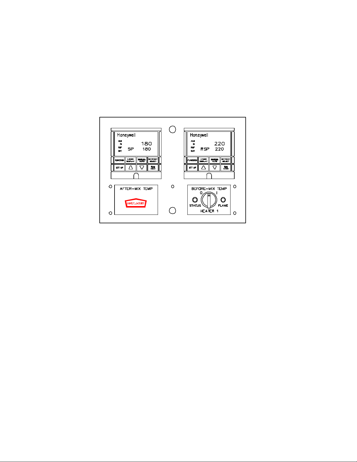
shutdown of the burner. If the valves fail a test, an alphanumeric display notifies the
operator, at both the console and burner cabinet, of the problem and more
specifically, where to look for the suspect valve. If the valves pass the test, an
alternate test is used following the next shutdown. This routine is repeated for the life
of the heater. The combustion control computer checks for other safety and
performance problems and notifies the operator with clear alphanumeric descriptions.
The PLC maintains an error history with the time and date that each problem
occurred. (DUAL-FUEL ONLY)
♦When the burner flame goes out during operation on older heaters, it is customary for
the flame safeguard relay to fire the sparkplug immediately in an attempt to reignite.
If air flow has been choked enough to produce an explosive mixture, this can be
serious. If our burner should flameout, it will first close all fuel valves, then wait for
air to purge the drying system. It then proceeds to restart the burner, observing all
safety precautions, including checking for flame relay problems.

PAGE3of61 HO-7-1237 & HO-4-1234 OIL-FIREDHEATERS
© SAMUEL JACKSON, INCORPORATED 2003 ALL RIGHTS RESERVED
HEATER OPERATION
HOW DO I TURN IT ON?
The heater is turned on by momentarily turning the START-STOP (O -I) selector switch to the
right and releasing it. This can be done either at the remote control station or at the "LOCAL
PANEL" (Figure 1) in the Heater's upper cabinet.
Figure 1 –Local Panel 14-3567.6
After the switch is turned and released, observe the display. The alphanumeric display at the
remote control (optional) and control cabinet are identical. The heater’s various operations will be
displayed as the self-checks and ignition sequence are performed. The digital temperature
controllers will energize during this sequence and complete their self-checks just before flame is
established. The STATUS light will remain on throughout this process. After approximately 20
seconds, the burner will attempt ignition. If ignition fails, the heater controls will automatically
make two more attempts following appropriate air purge delays.
BLINKS TO INDICATE ERROR OR
ALARM CONDITION AND
ACCESS TO TEST PROGRAM
DISPLAYS OPERATION MODE AND
ERRORS OR ALARMS
PRESS TO RESET
ALARM OR ERROR
USED TO VIEW ERROR
LOG AND ACCESS
TEST PROGRAM
TURN RIGHT MOMENTARILY TO START
TURN LEFT MOMENTARILY TO STOP

PAGE4of61 HO-7-1237 & HO-4-1234 OIL-FIREDHEATERS
© SAMUEL JACKSON, INCORPORATED 2003 ALL RIGHTS RESERVED
WHY IS THERE A DELAY AFTER I TURN IT ON?
When the STATUS light comes on, the combustion control computer begins opening and closing
valves to test the integrity of various safety switches located in the heater's control cabinet. If it
finds a problem with one of these devices, it alerts the operator on the displays with a description
of the problem.
These diagnostics are performed every time the heater is started and continue during operation
until approximately 10 minutes after the heater is turned off. The status of post-burn testing is
shown on the displays with the time remaining.
TIPS
Always leave power on the heater during gin season. There is a permanent memory in the
combustion control computer that remembers when you turned off the power and did not permit
the computer perform its safety switch test. It will result in ERROR 456 after 6 shutdowns with
no safety switch test.
To prevent lightning damage to the surge protector and controls in the off season, it is a good
idea to turn power off to the control cabinet until it is needed again.
ALARMS and ERRORS are fully described later in this manual. They may also be found on a
decal in the burner cabinet. The decal will be helpful when reviewing error history of the heater
as only time, date, and error number are displayed. ALARMS will warn the operator of an
impending problem and ERRORS will cause an immediate shutdown.
The STATUS light at the remote control station will blink to indicate an ALARM or ERROR. A
PLC low battery alert may occasionally be displayed which will not shut down the heater or be
recorded in its error history.
WHAT IS THE “TEST PROGRAM”?
The “Test Program” can be activated by a qualified service man or trained user to test the heater.
It is always performed in the Samuel Jackson factory before shipment of a new heater and
occasionally in the field when necessary for troubleshooting. This program allows the service
man to proceed step-by-step, through a series of tests where individual components of the heater
can be tested, calibrated, and adjusted.
The test program is described fully in the TEST SEQUENCE EXPLANATION section of the
manual.

PAGE5of61 HO-7-1237 & HO-4-1234 OIL-FIREDHEATERS
© SAMUEL JACKSON, INCORPORATED 2003 ALL RIGHTS RESERVED
WHERE DO I INSTALL THE THERMOCOUPLES?
The thermocouples are color-coded to assist the user in the installation of the correct
thermocouple in the before and after-mix locations. A thermocouple with red on the mounting
threads is for installation before the mix-point. This is the high limit thermocouple. The stainless
protection sheath is trimmed back exposing the sensing tip for fast response. This exposed
thermocouple should not be used in pipes with cotton flow.
A thermocouple with blue paint on the pipe threads is for installation after the mix-point. This is
the primary temperature sensor. The stainless sheath is left intact over the sensor bulb to protect it
from abrasion.
Referring to Figure 2, placement of the primary thermocouple on the inner radius side after an
elbow will protect it from abrasion. Angling the thermocouple 45 degrees in the direction of
cotton flow will prevent cotton and trash from tagging on the thermocouple.
In Samuel Jackson drying systems, the blue primary thermocouple is placed after the dryer’s
skimmer in the skimmed air. For tower drying systems, this thermocouple should be placed in the
top of the tower or in the transition immediately before the tower. Due to the responsiveness of
the temperature controls, placing this thermocouple farther down in the tower will cause control
instability.
For heaters operating with Hot Boxes and module feeders, with the cotton going to an unloading
separator, place the primary thermocouple in the seed cotton pipe before the unloading separator.
Call the factory for information on feed control operation when used in conjunction with a
module feeder and heater.
Figure 2 –Basic Temperature Control 14-3567.3

PAGE6of61 HO-7-1237 & HO-4-1234 OIL-FIREDHEATERS
© SAMUEL JACKSON, INCORPORATED 2003 ALL RIGHTS RESERVED
HOW DO I SET THE TEMPERATURE?
The temperature is set using the UP ARROW and DOWN ARROW buttons on the left
digital temperature controller on the 20000 Temperature Control (Figure 3) located at the
remote control station. The left controller is called the PRIMARY TEMP
CONTROLLER (After-Mix Temp). The controls must be energized before the
temperature can be changed. The last temperature set and held for one minute is
remembered by the controller.
As the temperature is changed on the left controller, this action will cause the HIGH
LIMIT CONTROLLER (Before-Mix Temp) on the right to respond. The HIGH LIMIT
CONTROLLER insures that the burner operates within a temperature range that is safe
for the product being dried (for example, 3500F, 1770C, is normally the high
temperature limit for cotton fiber).
There are two temperatures displayed on each controller during burner operation. The
bottom number is the desired temperature. It is called the setpoint temperature (SP). The
top number is the measured temperature. It is called the process variable (PV).
Both of the controllers have arrow buttons. In addition, both controllers have a button
marked SETPOINT SELECT. To bypass the modulating high limit setting, press the
SETPOINT SELECT button and use the arrow buttons to set the desired temperature.
The letters RSP (for remote setpoint) preceding the setpoint temperature will be replaced
with the letters SP when the SETPOINT SELECT button is pressed. The operation of the
automatic shutdown high temperature limit is preserved even when the modulating high
limit setting is bypassed.
Pressing SETPOINT SELECT button again will put the controller back into RSP mode.
A bright rectangle will appear on the left of the control display indicating when the
Figure 3 -20000 Temperature Control 14-3567.2

PAGE7of61 HO-7-1237 & HO-4-1234 OIL-FIREDHEATERS
© SAMUEL JACKSON, INCORPORATED 2003 ALL RIGHTS RESERVED
controller is communicating with another controller and is ignoring the arrow buttons.
This is the normal operating mode for the high limit controller. The HIGH LIMIT
CONTROLLER will automatically energize in the RSP mode regardless of whether the
controller was in SP or RSP mode before shutdown.
High temperature limit values of 3500 F (1770 C) are preset at the factory as normal
limits. Contact the factory for help in changing these limits if needed.
HOW DO I USE THE OPTIONAL AUTOMATIC MOISTURE CONTROL?
With our optional automatic moisture controls, the temperature on the PRIMARY TEMP
CONTROLLER is automatically adjusted based on incoming moisture content of the
cotton. We call this arrangement “Feed-Forward Control”.
To bypass the automatic moisture controls, press the SETPOINT SELECT button to
make the rectangle disappear on the PRIMARY TEMP CONTROLLER and use the
arrow buttons to set the desired temperature. The letters RSP (for remote setpoint)
preceding the setpoint temperature will be replaced with the letters SP when the
SETPOINT SELECT button is pressed. The high limit controller will still operate in this
mode.
Figure 4 shows the feed-forward control with a moisture sensor in the storage bin of a
feed control. The moisture control is adjusting the temperature of one heater that may be
part of either a Samuel Jackson drying system or tower drying system.
Figure 4 –Basic Feed-Forward Moisture Control 14-3567.4

PAGE8of61 HO-7-1237 & HO-4-1234 OIL-FIREDHEATERS
© SAMUEL JACKSON, INCORPORATED 2003 ALL RIGHTS RESERVED
Other sensor arrangements are available including a floating sensor (called the SLED) for
cotton module feeder belt conveyors. Call the factory for more information.
During automatic moisture control, the PRIMARY TEMP CONTROLLER also has RSP
displayed in front of the setpoint temperature indicating that it is communicating with the
moisture control system. A setpoint (SP) is provided on the moisture control to allow the
ginner to bias the general drying temperature level upward or downward.
Raising the SP up on the moisture control will provide lower drying temperatures, while
lowering the SP will provide higher temperatures. A decal is provided on the face of the
moisture control as a reminder of the SP logic.
Notes:
A -Use this arrangement for tower drying systems where both first and
second stage heater temperatures are adjusted automatically with the
moisture control.
B -This arrangement is used for Samuel Jackson drying systems using more
than one heater. One PRIMARY TEMP CONTROLLER is used for
measuring the temperature after a dryer. Its SP temperature is
automatically adjusted by the moisture control as before. The one
PRIMARY TEMP CONTROLLER adjusts the temperature RSP’s of each
of the heaters’ HIGH TEMPERATURE LIMIT CONTROLLERS.

PAGE9of61 HO-7-1237 & HO-4-1234 OIL-FIREDHEATERS
© SAMUEL JACKSON, INCORPORATED 2003 ALL RIGHTS RESERVED
WHAT IS THE OPTIONAL 20050 DIAGNOSTIC MODULE?
The optional “20050 DIAGNOSTIC MODULE” (Figure 5) is located at the remote
control station with the TEMPERATURE CONTROL. The alphanumeric display shows
the heater’s status, errors, and alarms when they occur.
Figure 5 -20050 Diagnostic Module 14-3567.9
The reset button and +/-switch have identical functions on both the DIAGNOSTIC
MODULE and the LOCAL PANEL located in the heater cabinet. This arrangement
allows access to the test program from the remote control station as well as the heater
cabinet. See section on TEST SEQUENCE EXPLANATION for full details on using the
test program.
The ALARM and ERROR history can also be viewed at the console. See the section on
ERROR and ALARM LOGGING SYSTEM for information on using this special feature.
DISPLAYS OPERATION MODE
AND ERRORS OR ALARMS
PRESS TO RESET
ALARM OR ERROR
USED TO VIEW ERROR
LOG AND ACCESS TEST
PROGRAM

PAGE10 of 61 HO-7-1237 & HO-4-1234 OIL-FIRED HEATERS
© SAMUEL JACKSON, INCORPORATED 2003 ALL RIGHTS RESERVED
ERROR AND ALARM LOGGING SYSTEM
The ERROR and ALARM LOGGING SYSTEM is a new feature for the Oil-Fired Heaters and
is designed to make troubleshooting easier for both the user and Samuel Jackson service
personnel. This system remembers the last 500 ERRORS and ALARMS, thus showing a
history of past problems. Alphanumeric displays located in the LOCAL PANEL (See Figure
1) and at the optional DIAGNOSTIC MODULE (See Figure 5) show the code number for the
ERROR or ALARM along with the month, day and time of occurrence.
Access to the system is easy and can be done at either display with the burner on or off. Turn
the +/-switch to the right (+) and hold for 5 seconds, then release. The display changes to
show Error Log #001 which is the most recent ERROR OR ALARM to occur. Use the +/-
switch to increment (+) to earlier logs or decrement (-) to the latest. Log entries are in a first-
in first-out stack, therefore Error Log #500 is replaced when another log event occurs.
Figure 6 shows a typical Error Log display. Error Log #002 is shown with a code of 421 that
occurred on 08/19 (August 19) at 16:49 (4:49 PM). Referring to the DIAGNOSTIC CODES
decal located on the heater cabinet door, Code 421 is an ALARM that air flow went off for a
moment. A more detailed description of the codes are given in the ERROR and ALARM
EXPLANATIONS section of the Service Manual. For the Error Log, no distinction is made
between ALARMS or ERRORS.
Figure 6 -Error Log Display 14-3567-7
To quickly advance through earlier logs, press the RESET button while in the logging
system. Each press of the RESET button will increment the log number to the next 50th
entry.
There are two ways to exit the logging system. Turn the +/-switch to the left (-) and hold for
5 seconds. Also, the display will change back to the normal operation mode screen after two
minutes of inactivity.
The time and date can be set in Step 1 of the Test Program described later in this manual.

PAGE11 of 61 HO-7-1237 & HO-4-1234 OIL-FIRED HEATERS
© SAMUEL JACKSON, INCORPORATED 2003 ALL RIGHTS RESERVED
ERRORS AND ALARMS
HO-7-1237 & HO-4-1234 OIL-FIRED HEATERS
CODE ERR/ALM DESCRIPTION
420 EAIR FLOW SWITCH ON MORE THAN 24 HOURS
421 AMOMENTARY LOW AIR FLOW POSSIBLE CHOKE
422 ELOW AIR FLOW FOR MORE THAN 3 SECONDS
425 EOIL LOW PRESSURE CHECK SUPPLY AND FILTERS
426 EOIL HIGH PRESSURE
430 EOIL LOW PRESSURE SWITCH FAILED
431 ELOW ATOMIZING AIR PRESSURE
432 EATOMIZING AIR PRESSURE SWITCH FAILED
433 EMODULATING MOTOR FAILS TO CLOSE
434 EMODULATING MOTOR FAILS TO OPEN
435 ELOW COMBUSTION AIR PRESSURE
436 ECOMBUSTION AIR PRESSURE SWITCH FAILED
441 EFAN INTERLOCK HAS BEEN BYPASSED
442 EAIR FLOW SWITCH HAS BEEN BYPASSED
443 ENO FAN INTERLOCK. IS FAN ON?
444 EEXCESSIVE FLAME FAILURES
446 AFLAME NOT ESTABLISHED
451 AFLAME FAILED IN OPERATION
453 EFLAME SIGNAL BEFORE SPARK BEFORE FUEL
455 EFLAME SIGNAL DURING SPARK BEFORE FUEL
456 ENO SAFETY SWITCH TEST PERFORMED LAST SIX SHUT
DOWNS
457 * EGAS LOW PRESSURE (DUAL-FUEL MODEL)
458 * EGAS VALVE LEAK, UPSTREAM (DUAL-FUEL MODEL)
459 * EGAS VALVE LEAK, DOWNSTREAM (DUAL-FUEL MODEL)
460 * EGAS LOW PRESSURE SWITCH NOT WORKING (DUAL-
FUEL MODEL)

PAGE12 of 61 HO-7-1237 & HO-4-1234 OIL-FIRED HEATERS
© SAMUEL JACKSON, INCORPORATED 2003 ALL RIGHTS RESERVED
ERRORS AND ALARMS, continued
HO-7-1237 & HO-4-1234 OIL-FIRED HEATERS
CODE ERR/ALM DESCRIPTION
461 * EGAS HIGH PRESSURE. CHECK GAS REGULATOR
(DUAL-FUEL MODEL)
462 EHIGH TEMPERATURE LIMIT WIRING ERROR
463 EAIR HIGH TEMPERATURE LIMIT EXCEEDED
464 EHIGH TEMPERATURE AT BURNER HEAD
470 ALERT † LOW PLC BATTERY
472 AFLAME SIGNAL LASTS TOO LONG AFTER SHUTDOWN
480 AHOT BOX TRASH GATE OPEN MORE THAN 20 SECONDS
481 EHOT BOX TRASH GATE OPEN MORE THAN 2 MINUTES
484 ECOMBUSTION FAN MOTOR OVERLOAD
485 EFUEL PUMP MOTOR OVERLOAD
490 EPOWER FAULT DURING OPERATION STAGE
499 EUSER SPECIFIED TIME FOR SHUTDOWN
E320 TIME OUT
E042 NO CPU BATTERY
† ALERTS ARE NOT LOGGED
* DUAL-FUEL OPTION ONLY

PAGE13 of 61 HO-7-1237 & HO-4-1234 OIL-FIRED HEATERS
© SAMUEL JACKSON, INCORPORATED 2003 ALL RIGHTS RESERVED
ERROR AND ALARM EXPLANATIONS
HO-7-1237 & HO-4-1234 OIL-FIRED HEATERS
(FOR SOFTWARE VERSIONS 1.0 AND LATER)
PRELIMINARIES -- As explained in the Heater Operation section, ERRORS will cause the
burner to automatically shut down. ALARMS will permit the burner to continue operation but
warn of conditions which may cause a shutdown if left unattended. In each case, the
DIAGNOSTIC CODE with a brief description of the ERROR or ALARM will be shown on the
display screen (Figure 7) located on the LOCAL PANEL in the heater cabinet and on the optional
20050 DIAGNOSTIC MODULE located at the remote control station.
Figure 7 -ERROR and ALARM Condition Display 14-3567.8
The display will continue to show the ALARM or ERROR until the RESET button is
pressed. Only one ALARM or ERROR condition is displayed at a time. The oldest
unacknowledged ALARM condition is shown even if the burner shuts down due to an
ERROR. Pressing the RESET button will show consecutive ALARM conditions leading
up to the shutdown ERROR.
* ERROR 420
AIR FLOW SWITCH ON MORE THAN 24 HOURS: The air flow switch (AFS) must be
exercised periodically to insure its proper operation. If the burner and fans have run
continuously for over 24 hours, the burner will NOT shut down due to this ERROR,
however if the burner is turned off and an attempt is made to restart it without turning off
the fans, it will not start and will display ERROR 420. The RESET button will NOT
allow restart. The fans MUST be turned off and then back on to allow the burner to start
again. If the operator is aware of the safety reasons for this air flow switch check and
desires to not turn the fans off, a passcode to bypass this ERROR
is described in the footnote for this section.

PAGE14 of 61 HO-7-1237 & HO-4-1234 OIL-FIRED HEATERS
© SAMUEL JACKSON, INCORPORATED 2003 ALL RIGHTS RESERVED
ALARM 421
MOMENTARY LOW AIR FLOW: This ALARM is an indication that a choke of the
airflow is occurring. It is displayed when the air flow switch goes off and comes back on
in less than 3 seconds.
ERROR 422
LOW AIR FLOW MORE THAN 3 SECONDS: This ERROR occurs when the airflow is
interrupted for more than 3 seconds. Verify proper airflow and adjust switch if
necessary.
ERROR 425
OIL LOW PRESSURE: The oil pressure fell below 45 psi. Check fuel pump rotation
when restart is attempted. If fuel pump rotates correctly, check the following: Check for
empty oil supply tank. Look for a closed valve in the supply pipe. Clean both of the oil
filter screens (in the lower cabinet and on the burner). Check for oil leaks which could let
air leak into supply pipe and cause pressure to fluctuate. Run the test program to adjust
the oil pressure. Remember that the oil pressure determines the maximum heat output and
that the oil pressure should be adjusted equal to the air pressure. Oil pressure higher than
air pressure can result in smoky operation and difficulty in starting.
ERROR 426
OIL HIGH PRESSURE: A shutdown due to this error is to prevent rupturing the fuel line
hoses from high oil pressure (over 90 psi). Check to see if the Fuel Pressure Relief Valve
(FPR) is jammed shut or its discharge connection is closed off. If this is not the case,
check to see if the Oil High Pressure Switch (OHP) has been adjusted to a pressure lower
than the setting of the FPR.
ERROR 430 *
OIL LOW PRESSURE SWITCH FAILED: The Oil Low Pressure Switch (OLP) failed to
turn off when the fuel pump was off. Check the OLP to see that its contacts have not been
bridged and that it is adjusted properly. Run the test program to check its adjustment.
ERROR 431
LOW ATOMIZING AIR PRESSURE: The atomizing air pressure fell below 45 psi. This
may be caused by an inadequate air compressor, a closed valve in the supply line or an
unusual usage of compressed air elsewhere in the plant. Dependable air pressure is
essential for the proper operation of the burner. The pressure shown on the air pressure
gage in the cabinet should be equal to the oil pressure, normally about 60 psi.

PAGE15 of 61 HO-7-1237 & HO-4-1234 OIL-FIRED HEATERS
© SAMUEL JACKSON, INCORPORATED 2003 ALL RIGHTS RESERVED
ERROR 432 *
ATOMIZING AIR PRESSURE SWITCH NOT WORKING: The Atomizing Air Pressure
Switch (AAP) told the PLC that air pressure was present although the air valve had not
been opened. Check for a leaking air valve, defective AAP, or a bridged circuit in the
AAP.
ERROR 433
MODULATING MOTOR FAILS TO GO TO CLOSE: There is a limit switch indicating
when the burner is in the low fire position. The PLC demands that this switch be ON in
the low fire position and OFF as the valve opens. If burner throttle is in the low fire
position, check low fire switch adjustment. If low fire position is not attained, run the test
program to Step 6 and test the operation of the Modulating Motor (MM). Check for
proper voltage on terminals L1 and L2 of MM.
ERROR 434 *
MODULATING MOTOR FAILS TO OPEN: This is similar to ERROR 433, and the same
things should be checked.
ERROR 435
LOW COMBUSTION AIR PRESSURE: This error occurs when the Combustion Air
Pressure Switch (CAP) senses insufficient combustion air pressure (less than 1 inch w.c.)
during certain steps of the operating program. Check for proper rotation of the
combustion air fan motor FM, and make sure the overload relay MOL1 for this motor is
not tripped. Reset MOL1 if tripped. After verifying good combustion air pressure
(through the tubes going to CAP), check for proper operation of CAP.
ERROR 436
COMBUSTION AIR PRESSURE SWITCH FAILED: The combustion air fan is killed
prior to trial for ignition. The pressure must fall to 1 inch w.c. (25 mm) and turn off
Combustion Air Pressure Switch (CAP) within 15 seconds or this error will be activated.
Look for wrong adjustment of CAP or bridging of its contacts. See Step 9 in the test
program.
ERROR 441
FAN INTERLOCK HAS BEEN BYPASSED: Samuel Jackson Heaters are provided with a
fan interlock to provide immediate shutdown of the heater when the fans are turned off.
This error indicates that an electrical signal is being received through the fan interlock
with no airflow present, effectively bypassing this important safety feature.

PAGE16 of 61 HO-7-1237 & HO-4-1234 OIL-FIRED HEATERS
© SAMUEL JACKSON, INCORPORATED 2003 ALL RIGHTS RESERVED
The external electrical connection diagram shows the fan interlock between terminals 50
and 10 on the 20000 remote temperature control. Sometimes the installing electrician
substitutes an electrical interlock on the motor starter or a relay contact output from a
central PLC control system to accomplish the same task. Any of these methods of fan
interlocking is acceptable. A fan interlock of some sort must be present to avoid this
error.
ERROR 442
AIR FLOW SWITCH HAS BEEN BYPASSED: This error indicates that an electrical
signal is being received from the air flow switch with no fan interlock signal present 2
minutes after turning the Heater off, effectively bypassing this important safety feature.
Check the adjustment of the air flow switch (AFS) and verify its operation.
ERROR 443 *
NO FAN INTERLOCK. IS FAN ON?: This ERROR is caused when an attempt is made to
start the heater when no fan interlock signal is present. A fan interlock relay is supplied
with the 20000 remote control to provide instant shutdown of the burner when the fan is
stopped. The installing electrician is responsible for wiring the coil of this relay to the
fan circuit. Sometimes the installing electrician substitutes an electrical interlock on the
motor starter or a relay contact output from a central PLC control system to accomplish
the same purpose. Any of these methods of fan interlocking is acceptable.
ERROR 444
EXCESSIVE FLAME FAILURES: During ignition and operation, flame failures are
counted. When the total comes to 3, the PLC shuts the Heater down on ERROR 444.
Use the error log to determine which alarms the flame failure triggered. Knowing which
three alarms caused the error will help determine the problem.
ALARM 446
FLAME NOT ESTABLISHED: This ERROR means that the burner failed to light during
its ignition sequence. See the maintenance tips later in this section. The Heater will not
attempt to restart if ERROR 456 NO SAFETY SWITCH TEST PERFORMED LAST SIX
SHUTDOWNS occurs and is reset without allowing time for test.
ALARM 451
FLAME FAILED IN OPERATION: This ALARM means that the burner failed after the
flame had been established. See maintenance tips below. The Heater will not attempt to
restart if ERROR 456 NO SAFETY SWITCH TEST PERFORMED LAST SIX
SHUTDOWNS occurs and is reset without allowing time for test.

PAGE17 of 61 HO-7-1237 & HO-4-1234 OIL-FIRED HEATERS
© SAMUEL JACKSON, INCORPORATED 2003 ALL RIGHTS RESERVED
TIPS
THE FOLLOWING MAINTENANCE TIPS WILL HELP TO MINIMIZE FLAME
FAILURE ALARMS:
•Clean the spark ignitor if it appears dirty. Look for oil on the spark ignitor. See
drawing in Service Manual entitled ADJUSTMENT OF 12796 AND 14200 SPARK
IGNITORS for correct adjustment.
•Check for proper clamping position of the spark ignitor. See drawing referenced
above for this adjustment.
•Make sure that the oil purge in the test program was complete and that you see fuel
rising in the flowmeter without air bubbles when ignition is attempted. Verify that the
small purge cock at the burner head is closed.
•If you see a flame in the viewing window of the burner, but the flame light does not
come on, suspect a defective Flame Scanner (FS) or a defective Flame Relay (FLR).
Unscrew FS and test it with a lighted match while watching Input # 14 on the PLC or
the light on the Flame Relay.
ERROR 453
FLAME SIGNAL BEFORE SPARK BEFORE FUEL: This ERROR is normally caused
by a malfunction or tampering with the flame relay (FLR).
ERROR 455
FLAME SIGNAL DURING SPARK BEFORE FUEL: This ERROR is caused by the
Flame Scanner (FS) seeing the spark as a flame. Remove the scanner and verify that the
small orifice disk is in front of the lens. If the disk is there, the 3mm hole may need to be
smaller.
ERROR 456
NO SAFETY SWITCH TEST PERFORMED LAST SIX SHUTDOWNS: Automatic tests
for gas valve leaks (Dual-Fuel only) and bypassed air flow switch (AFS) or fan interlock
relay have been interrupted for the past 6 shutdowns. Each time the heater is turned off,
the PLC attempts to spend about 2 minutes (10 minutes for dual-fuel) performing these
tests. These tests can be interrupted by simply turning off the power or restarting the
heater before the 2 minutes (10 minutes for dual-fuel) has ended. The PLC demands
however, that these tests be performed at least once every 7 shutdowns. If each of the past
6 shutdowns have had the tests interrupted, the PLC will not start until the RESET button
is pressed (ERROR 456 will be displayed).
This manual suits for next models
1
Table of contents
Other SAMUEL JACKSON Heater manuals