USSC Wondercoal 2941 User manual

OWNERS MANUAL
Model 2941
WONDERWOOD
THERMOSTAT CONTROLLED WOOD BURNING CIRCULATOR
SAFETY NOTICE:
If this heater is not properly installed, a house fire may result.
For your safety, follow the installation directions.
Contact local building or fire officials about restrictions and
inspection requirements in your area.
CAUTION:
Read all instructions carefully before starting the installation
or operation of this heater.
Improper installation may void your warranty.
*ASSEMBLY
*INSTALLATION
*OPERATION
*REPAIR PARTS
C
O
M
P
A
N
Y
U
N
I
T
E
D
S
T
A
T
E
S
S
T
O
V
E
C
S
S
U
85947-J
HOW TO ORDER REPAIR PARTS
Thismanualwillhelpyoutoobtainefficient,dependableservice
from the heater, and enable you to order repair parts correctly.
Keep this manual in a safe place for future reference.
Whenwriting,alwaysgivethefullmodelnumberwhichisonthe
nameplate attached to the inside of the cabinet door of the
heater.
WONDERWOOD
When ordering repair parts or options, always
givethefollowinginformationasshowninthislist:
1. The PART NUMBER
2. The PART DESCRIPTION
3. The MODEL NUMBER: 2941
4. The SERIAL NUMBER:________________
Before installing your heater, fill in the serial number of your
heater in the space provided above.
United States Stove Company
227 Industrial Park Rd.
P.O.Box 151
South Pittsburg, TN 37380
(423) 837-2100
www.USSTOVE.com
United States Stove Company
227 Industrial Park Rd.
P.O.Box 151
South Pittsburg, TN 37380
(423) 837-2100
www.USSTOVE.com
DO NOT USE THIS HEATER IN A MOBILE HOME OR TRAILER
Tested to UL 1482 & CAN/ULC-S627

219
F36 BLOWER KIT
An Optional Blower kit is available for the 2941 Wonderwood
automatic wood burning circulator heater. If this kit is not available
where you have purchased this Wonderwood heater, you can
purchase the F36 Blower Kit directly from the factory. To order
contact the United States Stove Company at the address and
telephone number given on the back page.
TOOLS AND MATERIAL NEEDED
TOOLS
Pencil
6 Foot Folding rule or tape
Tin Snips
Drill, hand or electric
Drill bit, 1/8" dia.
(for sheet metal screws)
Gloves
Screwdriver (blade-type)
5/16" Nut Driver or
5/16" Socket w/Ratchet
MATERIALS
Chimney Connection- 6" Dia. Black
Steel (24 Ga. minimum): Straight or
corrugated elbow (as required)*
1/2" Sheet Metal Screws
6" Inside Diameter Underwriters
Laboratories (UL) listed Residential
Type and Building Heating Appliance
Chimney, Type "HT", or 6" existing
Masonry Chimney with flue liner.
Floor Protector Material: 3' x 4'-6" as
specified on page 4.
Furnace Cement (Manufacturer
recommends: Rutland Code 78 or
Equivalent)
* Avoid adjustable elbows, they leak!
CIRCULATOR DIMENSIONS
Fig. 1
32 1/4
12 1/2
33 1/2
4 1/8
4 1/4
19 1/4
CENTER LINE OF 6"
CHIMNEY CONNECTOR
24
TOP OF FLOOR PROTECTOR
CENTER LINE
OF 6"
CHIMNEY
CONNECTOR
WONDERWOOD
RULESFORSAFEINSTALLATIONANDOPERATION
Read these rules and the instructions carefully.
SAFETYNOTICE:Ifthisheaterisnotproperlyinstalled,ahousefiremayresult. For
your safety, follow the installation directions. Contact local building or fire officials
about restrictions and installation inspection requirements in your area.
1.
Check local codes. The installation must
complywiththeirrulings.Donotinstallthis
heaterin a mobilehome or trailer.
2. Alwaysconnectthisheatertoachimneyor
vent to the outside. Never vent to another
roomor insidea building.
3. DonotconnectaWOODburningheaterto
an aluminum Type B gas vent. This is not
safe and is prohibited by all codes. This
heater requires connection to approved
chimneys:Eitherafactorybuilt6"UL103HT
or a lined and approved and recently in
spected and cleaned masonry chimney
with a 6" flue, preferably round. A larger
masonry flue may be used, so long as the
flue-sectiondiameterisnotgreaterthan50
sq. in.
Thechimneyportion(whetherfactory-built

18 3
BAROMETRIC DRAFT REGULATOR
Model DR6
SAFETY NOTICE
In the unlikely event that your 2941 "overfires" (a condition evidenced by elbows,
stovepipes, and connectors glowing red in appearance or otherwise discoloring),
thenyourinstallationissubjecttoexcessivedraftcreatedbyeitherachimneytootall
or too great in diameter in conjunction with its height, or some other factor of an
indeterminate cause. In this event, you should install a barometric draft regulator.
Such installation will preclude any overfiring and/or any hazardous consequences
of potential overfiring.
Barometricdraftregulatorsaregenerallyavailablewhereyoupurchasedyourstove
ormay be ordereddirectly from UnitedStates Stove Companyat a nominalcharge.
2001 Consumer Price:
$24.00 - Includes Shipping and Handling
NOTE:
DURING OPENING AND CLOSING OF THE FEED AND ASH DOORS
OF THIS HEATER, IT MAY SEEM THAT THE FIT OF THE DOOR IS
"TOO TIGHT". AS THE HEATER IS FIRED, THE GASKETING
"SETTLES" OR "SEATS" ITSELF IN THE DOOR. THE TIGHT FIT AT
THE FACTORY AND BEFORE THE HEATER'S INITIAL FIRING IS TO
INSURE A GOOD SEAL AFTER THE GASKETING "SETTLES".
NOTE:
FOR YOUR SAFETY, WE RECOMMEND INSTALLING SMOKE
DETECTORS IN YOUR HOME IF NOT ALREADY INSTALLED.
ormasonry)mustbetallenoughtoprovide
sufficient draft and safe exit of smoke and
combustionproducts.PleaserefertoPage
5.
4. Be sure that your Chimney is safely con
structedand ingood repair. Havethe chim
ney inspected by the Fire Department or a
qualifiedinspector (such as a Chimney
sweep).Your insurance company may be
abletorecommendaqualified inspector.
5. Inspectchimneyconnector and chimney
twicemonthlyduringtheheatingseasonfor
anydepositofcreosote orsootwhichmust
beremoved.
6. Provideairforcombustionfromoutsidethe
house into the room where the heater is
located.Iftheintakeisnotinthesameroom,
air must have free access to the room.
7. CAST IRON PARTS MUST BE "SEA
SONED" TO AVOID CRACKING. BUILD
ONLY SMALL FIRES ON FIRST USE.
8. To prevent injury, do not allow anyone to
use this heater who is unfamiliar with the
correctoperationoftheheater.Donotallow
children to use or in any way operate this
heater.
9. Forfurtherinformationonusingyourheater
safely, obtain a copy of the National Fire
ProtectionAssociation(NFPA)publication
"UsingCoalandWoodStovesSafely"NFPA
No.HS-10-1978.TheaddressoftheNFPA
isBatteryMarchPark,Quincy,MA.02269.
10.
Keep the ash pit section free of excess
ashes. Do not allow ashes to stack higher
than the sides of the ash pan.*
11.
DISPOSAL OF ASHES- Ashes should be
placedinametalcontainerwithatightfitting
lid. Keep the closed container on a non-
combustible floor or on the ground, well
awayfromall combustiblematerials. Keep
the ashes in the closed container until all
cindershavethoroughlycooled.Theashes
may be buried in the ground or used as
fertilizer.
12.CAUTION:Thespecialpaintsusedonyour
heatermaygive offsomesmokewhilethey
are curing during first few fires. Build small
firesatfirst. Themetalused inconstruction
of the heater has a light coating of oil. This
could give off smoke and/or odors when
heater is used for the first couple of times.
Thisshould disappear after a shortperiod.
Once this burn-off has occurred, it should
notreoccur.
13.CARING FOR PAINTED PARTS- This
heaterhasapaintedoutsidejacket,whichis
durablebutwillnotstandroughhandlingor
abuse.Wheninstalling yourheater, use
careinhandling.Cleanwithsoapandwarm
water when heater is not hot. DO NOT use
any harsh chemicals (acids or caustics) or
scouringpowder,asthesewearanddullthe
finish.
14.KEEPTHEFEEDDOOR,ASHDOORAND
CABINETDOORCLOSEDATALLTIMES
EXCEPTWHILETENDINGTHEHEATER.
DO NOT OVERFIRE THE HEATER. THIS
WILL HAPPEN IF THE FEED DOOR, OR
PARTICULARLYTHEASHDOOR,ISLEFT
OPENDURINGOPERATION.UNDEREX
TREME CONDITIONS THIS CAN PRO
DUCE DANGEROUS RESULTS. AT A
MINIMUM,ITWILLALLOWTHEPAINTTO
DISCOLOR.
* Never allow ashes to contact the grate(s).
CAUTION: DO NOT TOUCH THE
HEATER UNTIL IT HAS COOLED.
ALWAYS WEAR GLOVES WHEN
REFUELING THIS UNIT OR WORKING
WITH METAL CABINET PARTS.
MINIMUM CLEARANCES TO COMBUSTIBLE WALLS AND CEILINGS
Minimumclearancestounprotectedcombustiblewallsandceilingsasnotedbyfigures2through
4mustbemaintained. Drapes,curtains,furnitureandothercombustiblematerialsshouldbekept
muchfurtherawayfromtheheatertoavoidfire. Ifyouchooseto,youmayinstalltheheaterand
chimney connector closer to combustible surfaces than indicated by Figures 2 through 4 IF a
clearance reduction system is also installed to protect combustible ceilings and walls near the
heaterandchimneyconnector. However, therearelimits to howclosethe heaterandchimney
connectorcanbeinstalledtocombustiblesurfacesprotectedbyaclearancereductionsystem.
Acorrectlyinstalledclearancereductionsystemprotectsthecombustiblesurfaceswellbeyond
thesidesandabovethetopoftheheaterandbeyondthesidesandtopofthechimneyconnector
pipe.
Twocommontypesof clearancereductionsystemsuse sheetmetalwitha minimum thickness
of28gauge(galvanizedsteel,aluminum,copper)ora3-1/2inch(4inchnominal)thickmasonry
wall. Eitherof these materials mustbe spaced out 1 inch from the combustible surfaces. With
sheetmetal,non-combustiblespacersareusedtomaintainthe1inchairspace. Withamasonry
wall,metalwalltiesandfurringstrips,ifneededareusedtoanchorthebricktothewall. Toavoid
excessive heat transmission, the spacers or wall ties should not be placed directly behind the

25"
35"
16"
26"
54"
19 1/4"
36"
4 3/4"
NOTE: DASHED LINES SHOW
STRAIGHT UP AND THROUGH
THE WALL INSTALLATION
17" 32 1/4" 16"
FLOOR PROTECTOR
(TOP VIEW)
SIDEWALL
NON-COMBUSTIBLE
CONSTRUCTION IN
ACCORDANCE WITH
NFPA 211
12"
12"
WONDERWOOD
Fig. 2
Fig. 4
Fig. 3
4
REPAIR PARTS LIST - MODEL 2941 (SEE PAGE 18)
AUTOMATIC WOOD BURNING CIRCULATOR
Key No. Description Qty. Part No.
1 Heat Jacket Assembly 1 68619
2 Base Weldment 1 67859
3 Smoke Curtain 1 22090
* Smoke Curtain Bracket 2 22171
4 Flue Collar 1 40246
5 Flue Collar Gasket 1 88032
6 Draft Damper Frame 1 40075
7 Draft Control Damper 1 23476
8 Draft Damper Hinge Pin 1 17200
9 Clip Spring 1 83818
10 Fire Grate 2 40076
11 Liner 3 40100
12 Firebrick 10 89066
13 Top Brick Retainer 2 40132
FeedDoor Assembly 68621
Ash Door Assembly 68620
14 FeedDoor 1 40199
15 Ash Door 1 40289
16 DoorLatch 2 22108
17 DoorHandle 2 40091
18 FeedDoorRope Gasket 3.75FT 88033
19 Ash Door Rope Gasket 2.5FT 88033
20 1/4-20Kep Nut 2 83250
21 5/16 ID, 3/4 OD Washer 2 83045
22 LatchSpacer 2 21467
23 DoorHinge Pin (Short) 1 83872
24 DoorHinge Pin(Long) 1 23441
25 HeatShield 1 23475
26 DropWoodenHandle 1 89523
27 Ash Pan 1 67444
28 SolidDamper 1 D6
29 TopLiner 1 23474
30 HeatShield 1 22110
31 SecondaryHeatShield 1 22030
* NOT SHOWN
17
1. The chimney connection should be as airtight as possible. The heater must have its own
chimney flue. Do not connect this unit to a chimney flue serving another appliance. If there
is no chimney near where you wish to place the heater, you can use a UL 103HT Residential
Type and Building Heating Appliance Chimney (Fig. 5, 6, 6A & 6B).
2. Place the heater on solid masonry or solid concrete. When the heater is used on a
combustible floor protector of one layer of 3/8" millboard having a thermal conductivity of
K=0.84 BTU in./ft. 2 hr. Deg. F with 28-gauge sheet metal or a UL Listed floor protector. Have
thefloor protector extend 16" beyondthe door side of theheater and under the connectorpipe
in the back.
3. Check Figures 2, 3, and 4. Be sure you have the clearances shown from the heater and
the connector pipe to combustible surfaces. If you have a solid brick or stone wall behind your
heater, you can place the heater as close as you wish to the wall. If the wall is only faced with
brick or stone, treat it as a combustible wall.
LOCATING THE HEATER
AS A LOCATION IS SELECTED,
KEEP THE FOLLOWING IN MIND:
heaterorchimneyconnector. The1inchairspaceprovidesfreeaircirculation. Itisessentialthat
therebeopeningsatthetopandbottomoftheseclearancereducerssocoolaircanenteratthe
bottomand hotair exit at the top. It is the"chimney effect"whereby whenthe airin thespace is
heated,itrisesexitingfromthetopandbeingreplacedbycoolerairatthebottom,thatmakesthese
shieldseffective.
Masonry,orothernon-combustibleproducts,attacheddirectlytoacombustiblesurfacewithout
an air space offer very little protection and cannot be considered a clearance reducer unless
specifiedmaterials havebeen testedand listed for direct attachmentto acombustible surface.
Thesameappliesto thinveneerbrick andstonecoverings. These materials provideadequate
protection only when mounted on sheet metal with a 1 inch spacing to the wall.
A variety or prefabricated clearance reduction systems which have been tested and listed are
available through heater dealers. Always look for a safety listing label on the product when
selectingaclearancereductionsystemandmakesureitisdesignedforsolidfuelappliances. The
manufactures of these systems provide specific installation instructions that must be followed
exactlyfor a safe installation.

5
17
8
9
10
11
12
13
14
7
6
4
5
3
2
1
15
16
17
18
32
19
20 21
23
24
29
25
26
27 22
REPAIR PARTS
AUTOMATIC WOOD BURNING CIRCULATOR HEATER
MODEL 2941 - INTERIOR
16
22
21
20
30
31
28
16
of which is apparent: The chimney
providesameansforexhaustingsmoke
andfluegasesresultingfromcombustion
of the fuel. Secondarily, though, the
chimney provides "Draft" which allows
oxygen to be continuously introduced
into the appliance, so that proper
combustion is possible. As of April 1,
1987, all heaters and furnaces
manufactured by United States Stove
Company should be installed using a
factory built chimney that meets the
"TypeHT"requirementofUL103(when
a factory - built chimney is used).
IMPORTANT
*Size the chimney to the flue outlet on
the stove. (6" outlet = 6" I.D. chimney)
*Avoid using elbows except as
necessary (they reduce draft).
*Make sure all horizontal runs of con-
nector pipe go up hill (1/4" elevation for
each horizontal foot).
CHIMNEY CONNECTION
Two basic types of chimneys are ap-
proved for use with solid fuel: Factory-
builtandmasonry.Factory-builtchimney
must comply with UL103HT standard.
Do not expect your stove or furnace to
createdraft.Draftisnotafunctionofthe
appliance. Draft is purely a function of
the chimney. Modern stoves and
furnaces are much more air-tight and
efficient than those of the past and,
therefore require greater draft. A
minimum of .05, measured in water
column (gauges to measure chimney
draftarereadilyavailableatstoveshops
andareeconomicaltopurchaseorrent)
isrequiredforproperdraftingtoprevent
back-puffing, smoke spillage, and to
maximize performance.
Chimneys perform two functions - one
FIG. 5 FIG. 6
Cathedral Ceiling - Chimney
Cap Mandatory
PIPE
FLOOR PROTECTOR
REFER TO CHIMNEY
MANUFACTURERS PARTS
AND INSTRUCTIONS
2 FT MIN.
10 FT. 3 FT.
MIN.
BAROMETRIC
DRAFT CONTROL
(OPTIONAL)
11 FT. MIN.
CHIMNEY CAP MANDATORY
PIPE
FLOOR PROTECTOR
REFER TO CHIMNEY
MANUFACTURERS PARTS
AND INSTRUCTIONS
2 FT MIN.
10 FT. 3 FT.
MIN.
BAROMETRIC
DRAFT CONTROL
(OPTIONAL)
11 FT. MIN.
CHIMNEY CAP MANDATORY
31
30
DAMPER DAMPER

FLOOR PROTECTOR
2 FT MIN.
10 FT.
MINIMUM 3 FT.
MIN.
APPROVED COWL
6"
MIN.
6" MIN. APPROVED
THIMBLE
60" MIN.
615
FIG. 6B - Typical Masonry Chimney Installation
FIG. 6A - Thru-The-Wall Installation
THIMBLE
COLLAR
PIPE
NON-COMBUSTIBLE
WALL
FLOOR PROTECTOR CLASS A UL 103HT
CHIMNEY KIT INCLUDING
WALL THIMBLE.
BAROMETRIC
DRAFT CONTROL
(OPTIONAL)
KEY NO. PART NO. DESCRIPTION QTY.
1 89062 Cabinet Door Knob 1
2 83005 Screw (10-24 x 1/2) FL 1
3 83033 Screw (8-32 x 1/4) PH,TR,HD,Z 1
4 83093 Spring Latch 1
5 83244 Kep Nut (10-24) 1
6 67968 Cabinet Door Frame 1
7 86191 Thermostat Linkage 1
8 85381W Control Panel Plate 1
9 89142 Thermostat Knob 1
10 67725 Cabinet Front Assembly 1
11 67967 Cabinet Left Side 1
12 21593 Hinge Support 1
13 83833 Hinge Clip 1
14 67966 Cabinet Top 1
15 67743 Thermostat Assembly 1
16 21063 Back Brace 2
17 67514 Cabinet Back 1
18 89065 Door Hinge 4
19 67969 Cabinet Door 1
20 23477 Top Thermostat Shield 1
21 83406 10-16 x 3/4 TORX, WAF, HD,DP,Z 2
REPAIR PARTS
AUTOMATIC WOOD BURNING CIRCULATOR HEATER
MODEL NUMBER 2941
(SEE PAGE 16)
REPAIR PARTS LIST
DAMPER
DAMPER
BAROMETRIC DRAFT
CONTROL

14 7
CAUTION:
NOT ALL FIREPLACES
ARE SUITABLE FOR
INSTALLATION OF A WOOD
HEATER.
Many people may wish to convert an
existingfireplacetoheateruse.Usually,
safe connection of stovepipe to a ma-
sonrychimneyrequiresmoreeffortthan
connection to a prefabricated chimney.
Thefireplacemustbeclosedandsealed
atthedamperintheflue.Goodsealants
arehigh temperature caulking,ceramic
wool, and furnace cement. Always re-
member to inspect the masonry chim-
ney and fireplace. If necessary, clean
the flue and smoke shelf before begin-
ning your installation. Install the heater
intothechimneyso that the system can
be dismantled for cleaning and inspec-
tion.
Before deciding to convert your fire-
placeor existing chimney, keepinmind
thatolderfireplaces and their chimneys
are unsafe. They must be structurally
sound,andthefluelinermustbeingood
condition.Donotuse achimney if itis
unlined (should have a tile clay liner
to protect brickwork), have it relined
professionally.Clearancestocombus-
tiblesare explainedintheprevious sec-
tion on masonry chimneys. If you have
any questions regarding the condition
ofthe chimney,consultaqualified engi-
neer,competentmason,certifiedChim-
ney Sweep, or knowledgeable inspec-
tor.
Many prefabricated fireplaces fall into
the"zero-clearancefireplace"category.
This is a factory metal fireplace with
multi-layeredconstruction.Itisdesigned
to provide enough insulation and/or air
coolingsothatthebase,backandsides
can be safely placed in close contact
with combustible floors and walls. Al-
though many prefabricated fireplaces
have been tested by nationally recog-
nized organizations for use as fire-
places, they have not been tested to
acceptheaters.Infact,theiruseassuch
may void the manufacturer's warranty.
Steel-lined fireplaces, on the other
hand, can be used with heaters. These
unitsuse a 1/4-inchfireboxlinerand an
airchamberinconnectionwith8inches
of masonry to meet code. They contain
all the essential parts of a fireplace,
firebox, damper, throat, smoke shelf,
andsmokechamber.Manyofthemlook
exactly like a masonry fireplace and
must be checked closely for above re-
quirements before installing a coal
heater into them.
Another method frequently used by
some people is to vent the heater di-
rectly into the fireplace. This does not
meet code since the heater is being
vented into another appliance - the
fireplace. This method should not be
attempted because combustion prod-
ucts will deposit and build up in the
firebox or fireplace. Be certain not to
install a hazard in you house. You will
void your warranty with this installa-
tion.
VENTING INTO A FIREPLACE
(Not recommended)
18
15
1
2
17
6
3
5
16
10
19
13
12
9
7
4
8
11
REPAIR PARTS
AUTOMATIC WOOD BURNING CIRCULATOR HEATER
MODEL 2941 - EXTERIOR
14
21
WONDERWOOD

8
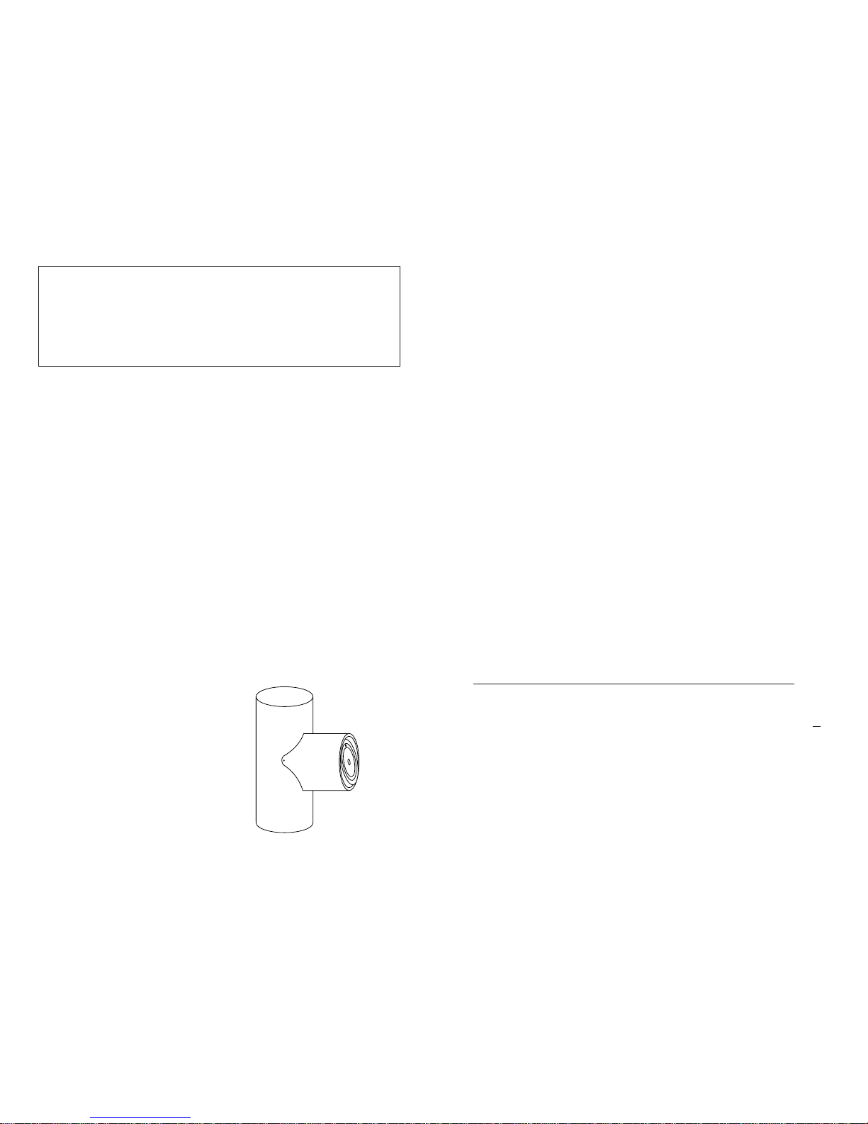
Install the stovepipe as far as possible
into the thimble, but not past the inside
of the flue lining. There should be a
small air space (approximately 1/2 in.)
between the stovepipe and thimble, al-
lowing for expansion of the stovepipe.
Seal this airspace with high-tempera-
ture caulking or ceramic wool. Finally,
be sure to wire the damper closed and
apply the same sealant you used at the
stovepipe and thimble junction.
Do not vent up through the fireplace
opening,regardlessof whether the fire-
place opening is closed.
MASONRY CHIMNEY have several
positiveattributes: If properly built, they
arequitedurable,andmosthomeowners
consider them more attractive perhaps
than a non-enclosed factory built
chimney. And,ifthechimney is located
withintheconfinesof the house (that is,
not attached to an exterior wall), its
mass alone will store heat longer and
continue to release the heat long after
the fire has died. Masonry chimneys
have many disadvantages though.
Masonry chimneys constructed on an
exterior wall are exposed to cold out-
door temperatures, promoting greater
heater loss, higher accumulations of
creosote,andreduceddraftwhichleads
topoorerheaterorfurnaceperformance.
FIREPLACE INSTALLATION
Connectionofthestovepipedirectlyinto
the existing masonry chimney over the
fireplace opening is the only approved
method. This installation performs bet-
ter, yielding easy to clean and inspect
forcreosote.Before beginning this type
of installation plan carefully; a high de-
gree of skill is required to insure safety.
An entry port for the stovepipe must be
cut through the chimney with minimum
damage to the fire clay liner. Some
involvedmeasurementsmayberequired
to locate the flue liner exactly. Before
cutting, take time to mark the size and
position of the entry port. Position the
entryport so that at least 8 inches ofthe
flue liner remains below the port.
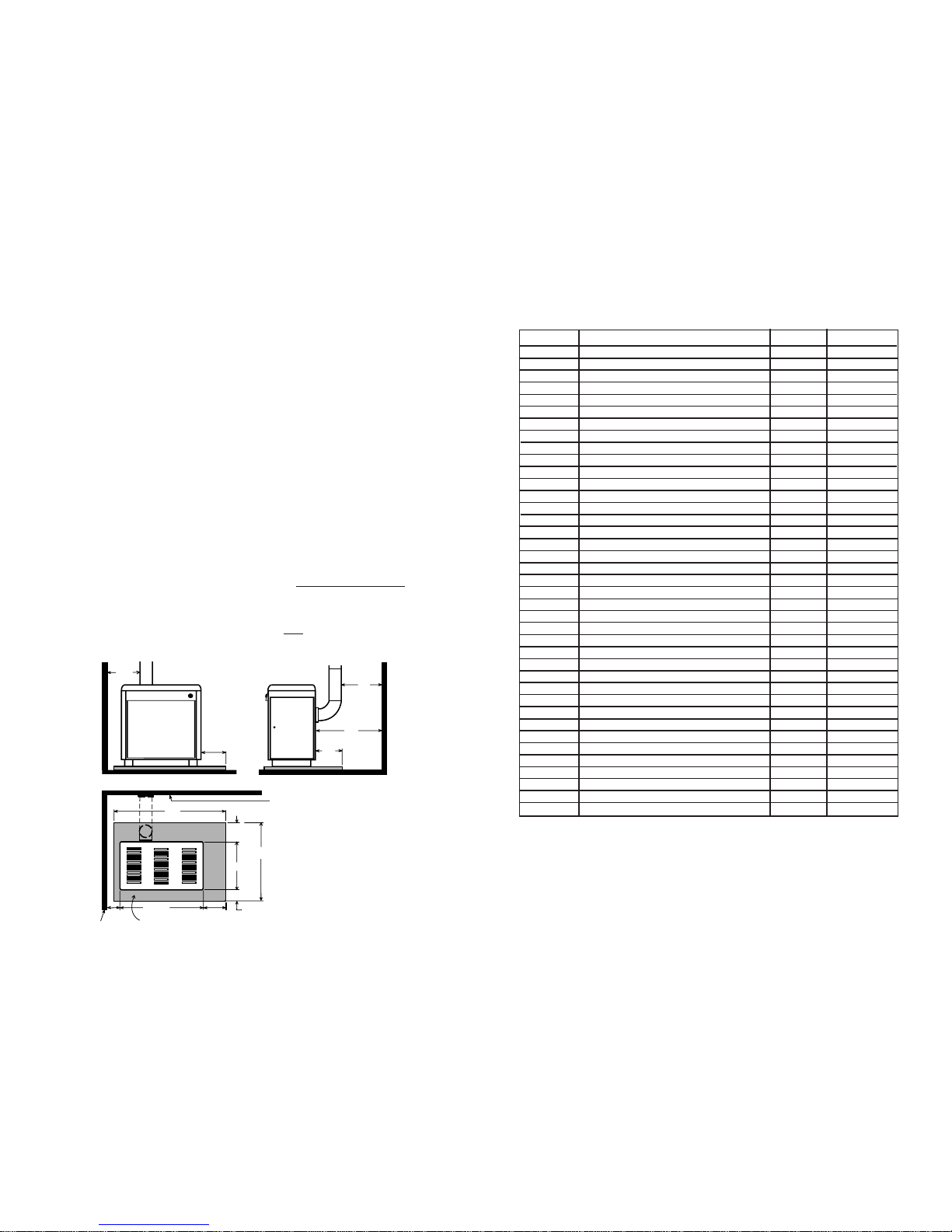
Keep in mind that wood mantels and
combustible trim around the fireplace
must have adequate clearances from
the heater and stovepipe or must be
protectedinanapprovedmanner.Also,
be sure to leave at least 24" clearance
between the top of the stovepipe and
the combustible ceiling or other com-
bustibles.Placingthecenteroftheentry
port 2 feet below the ceiling will insure
proper clearance for 6 inch, 8 inch, and
10 inch stovepipes. Next, install a fire
clay (at least 5/8 in. thick) or metal
thimble, being sure that the thimble is
flush with the inner flue lining. Secure
thethimbleinplacewithrefractorymor-
tar. The thimble should be surrounded
on all sides with 8 inches of brickwork
(solid masonry units) or 24 inches of
stone.
CAUTION
A chimney fire may cause ignition of wall studs or rafters which you
thought were safe distance from the chimney. If you have a chimney fire,
have your chimney inspected by a qualified person before using again.
Do not expect a heater to draw. It is the
chimney that creates the draft. Smoke
spillage into the house or excessive
build-up of water or creosote in the
chimneyare warnings that the chimney
is not functioning properly. Possible
causes are:
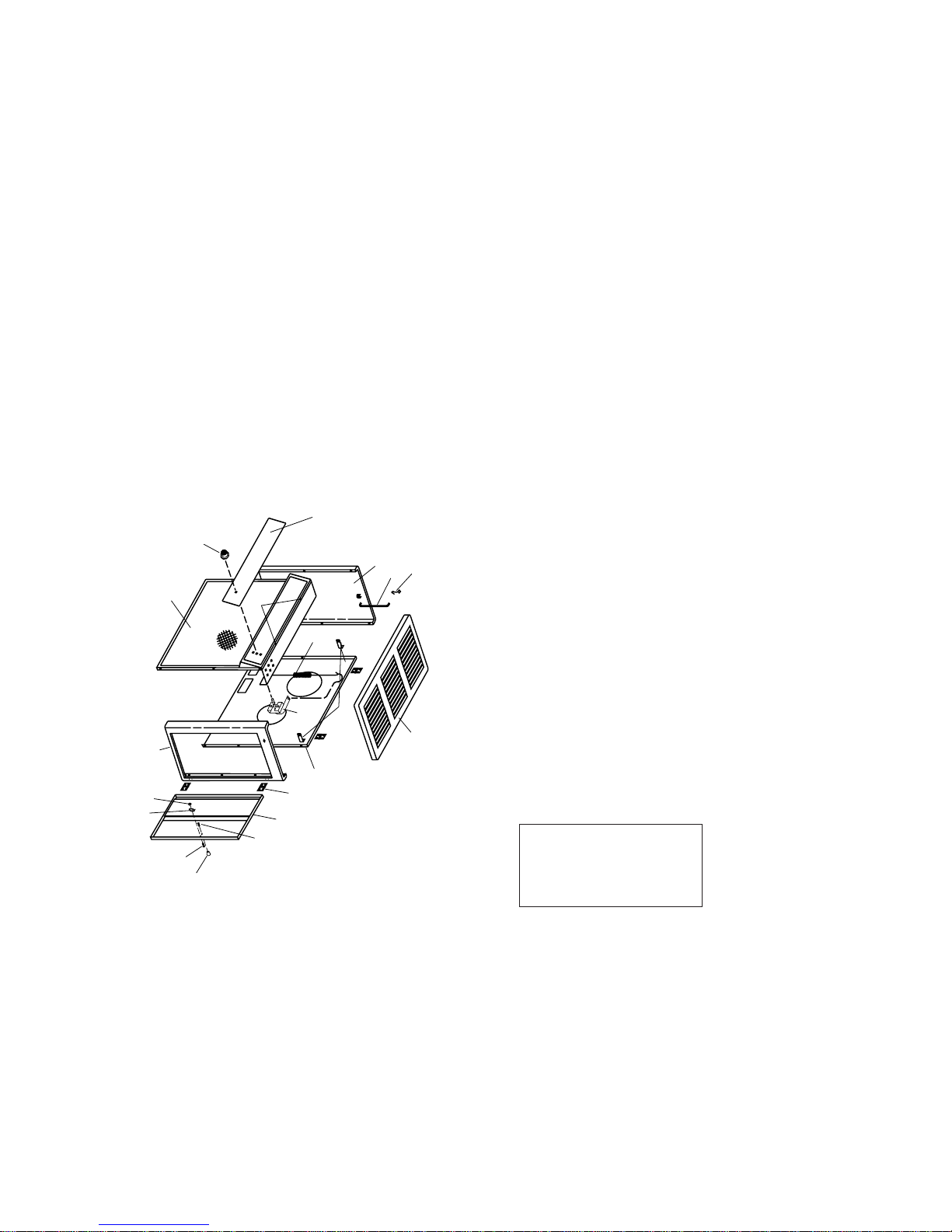
1. Theconnection pipe maybepushed
into the chimney too far, stopping the
draft (Fig. 8).
2. Two heaters connected into the
same chimney flue.
3. Samefluebeingusedtoventilatethe
cellarorbasement.Ifthereisacleanout
opening at the base of the chimney, it
must be closed tightly and sealed.
4. If the chimney is too cool, water will
condense in the chimney and run back
into the stove. Creosote formation will
be rapid and may block the chimney.
Operatetheheateratahighenoughfire
to keep the chimney warm preventing
this condensation. (Poorly insulated
chimney)
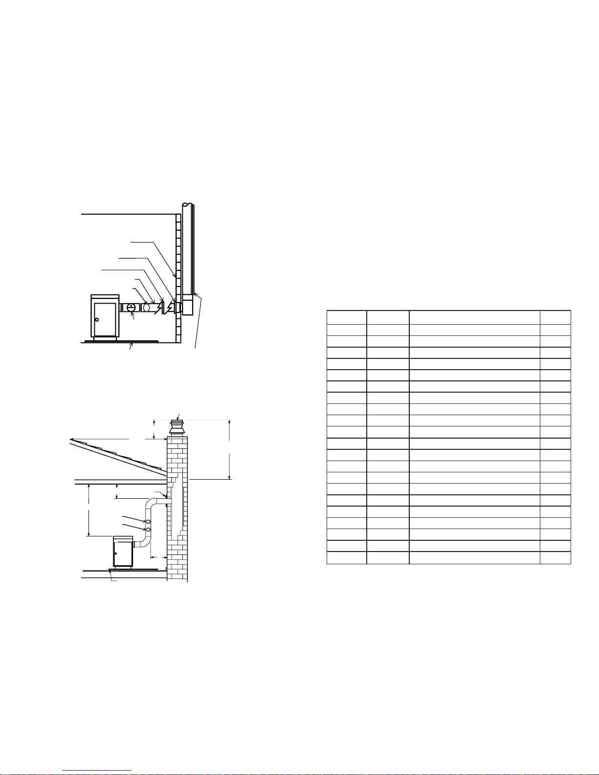
5. The chimney top may be lower than
another part of the house or a nearby
tree. The wind blowing over a house or
a tree falls on top of the chimney like
water over a dam, beating down the
smoke. The top of the chimney should
be at least 3 feet higher than any point
of the roof within 10 feet (Fig. 6).
6. Other chimney/flue inadequacies
covered else where in this manual.
If creosote has accumulated, it should
be removed.
Failure to remove creosote or soot may
cause a house fire. Creosote may be
removed by using a chimney brush or
othercommonlyavailablematerials. Or,
betteryet,byacertifiedchimneysweep.
Chimneyfiresburnveryhot.Ifthechim-
neyconnectorshouldglowred,immedi-
ately call the fire department, then re-
duce the fire by closing the inlet air
control and closing the damper in the
pipe.
CHIMNEY MAINTENANCE
CREOSOTE-FORMATION AND NEED FOR REMOVAL
NOTE:
A draft reading of .05 to .06 w.c. is suggested for proper burning of this
unit.
SERVICE HINTS
13
When wood is burned slowly, it pro-
duces tar and other organic vapors,
which combine with expelled moisture
to form creosote. The creosote vapors
condenseinthe relatively cool chimney
flue of a slow burning fire. As a result,
creosote residue accumulates on the
flue lining. When ignited, this creosote
makes an extremely hot fire.
The chimney connector and chimney
should be inspected at least twice
monthly during the heating season to
determine if a creosote build-up has
occurred.

9
When considering a masonry chimney,
round tiles are preferable to square or
rectangular, as round tiles have much
better airflow characteristics and are far
easier to clean. Unfortunately, most
North American chimneys use square or
rectangular tile liners that are really de-
signed for open fireplaces, not stoves or
furnaces. Of most importance, second
only to overall chimney height, is the
diameter of the flue liner itself. In most
instances, it should be sized to the appli-
ance; i.e., 6" flue outlet on the appliance
requires a 6" flue. The inner diameter
should never be less than the flue outlet
diameter and should never be greater
than50%oftheappliance flueoutlet.For
example, do not expect a wood burning
stove or furnace to function properly if
installed into a chimney with a flue liner
greater than 50% the appliance outlet -
- such as a 6" flue outlet requires a 6"
diameter for optimum drafting, but can
function well with an 8", but becomes
borderline beyond 8" diameter.
Masonry chimneys built of concrete
blocks without flue liners of at least 5/8"
fireclay do not meet modern building
codes. A
TYPE "A"
FIREPLACE
CONVERSION
Fig. 7
5/8" FIRECLAY
FLUE LINER
STOVEPIPE CONNECTOR
SEALED AT THIMBLE
HORIZONTAL 6" STOVEPIPE
(24 GAUGE) WITH 1/4"
RISE PER FOOT
6" STOVEPIPE ELBOW
CLEARANCE REDUCER
(FOR MANTEL)
6" STOVEPIPE - HAVING
THREE SHEET METAL SCREWS
PER JOINT OF STOVEPIPE
U.L. LISTED
FLOOR PROTECTOR DAMPER THROAT
CLOSED AND SEALED
solid fuel appliance must not be joined
to a chimney flue which is connected to
another appliance burning other fuels.
If your chimney has a typically oversized
flue liner of 8x12 inches or greater, or if it
is unlined, it will be necessary for you to
reline the chimney, using many of the
modernapproved and economical meth-
ods such as stainless steel, castable
refractory, or properly sized fireclay lin-
ings.
Ifyouhaveanyquestionregardingventing
your appliance, feel free to contact the
factoryattheaddressandphonenumber
on this Owner's Manual. You may also
contact NFPA (National Fire Protection
Association)andrequestNFPAStandard
211 (1984 Edition). Their address is
Battery March Park, Quincy,
Massachusetts 02269. Another helpful
publication is NFPA Standard 908,
available at the same address. Specify
1984 Edition on either of the above
publications.
The door knob is mounted inside of the cabinet door to facilitate
shipping and must be reversed for proper usage.
To get cabinet door open, place hand under cabinet frame (right
hand side of cabinet door) and push door out.
INSTALL THE CABINET DOOR KNOB USING THE STEPS
BELOW:
1. Remove the machine screw and door knob (Fig. 10).
2. Place door knob on outside of cabinet door. Then place
machine screw through hole and into door knob and tighten (Fig.
11).
CABINET DOOR KNOB ASSEMBLY
Fig. 10 Fig. 11
CABINET DOOR
KNOB
MACHINE
SCREW
12

CAUTION:
HOT WHILE IN OPERATION.
KEEP CHILDREN, CLOTHING
AND FURNITURE AWAY.
CONTACT MAY CAUSE
SKIN BURNS.
OPERATING INSTRUC-
TIONS
FUEL
Hardwood, 18" to 23" should be split
andairdried(seasoned)for6monthsto
obtain maximum burning efficiency.
Wood should be stored in a dry, well
ventilated area. A Wooden box or crate
is ideal for storage.
NOTE:USESOLIDWOODMATERIAL
ONLY. DO NOT USE COAL.
DO NOT USE MANUFACTURED OR
CHARCOAL LOGS!
LIGHTING
1. Set the thermostat on "High" for
maximum draft.
2. Open the feed door and place paper
andkindling on the grate for startingthe
fire.
3. Light fire and close feed door.
4. Add fuel after fire is burning briskly.
Usecarenottosmotherthekindlingfire.
5. Set thermostat higher or lower for
desired temperature.
ADDING FUEL
When possible, add small amounts of
fuel each hour or so instead of adding
large quantities of fresh fuel every 4 to
5 hours. This will give more complete
combustion and less build-up of tars or
soot in the chimney.
1. SetThermostattoHIGHbeforeopen-
ing feed door.
2. Empty ash pan regularly. Do not
allowashestobuilduptograteasgrate
will warp and burnout will occur, and
you might spill the ashes when remov-
ing the pan. Dispose of hot ashes prop-
erly (see Note 11 on Page 3).
10
GRASP TOP
HERE TO
OPEN
RULES FOR CONNECTOR PIPE INSTALLATION
1. Thecrimpedendofthestovepipefits
inside the heater flue collar. Install ad-
ditional pipe and elbow with the
CRIMPED END TOWARD THE
HEATER. This will allow any
condensationintheflueto runbackinto
theheater. Smokewillnotescapewhen
installed in this manner.
2. Slope any horizontal pipe upward
toward the chimney at least 1/4 inch for
each foot of horizontal run.
3. You must have at least 18 inches of
clearance between any horizontal pip-
ing and the ceiling.
4. The pipe cannot extend into the
chimney flue. (Fig. 8)
5. Seal each connector pipe joint with
furnace cement. Also seal the pipe at
the chimney.
6. Use 3 Sheet Metal screws at each
joint to make the piping rigid.
7. Itis recommended thatnomorethan
two 90 degree bends be used in the
stovepipe installation as more than two
may decrease the amount of draw and
if possible, use only corrugated (non-
adjustable)elbows.Theyaremuchmore
airtight.
8. The chimney connector must not
pass through an attic or roof space,
closet,oranyconcealedspace,orfloor,
ceiling, wall or combustive construc-
tion.
WONDERWOOD
WONDERWOOD
A
HOW TO LIFT THE TOP
CAUTION - DO NOT OPEN OR CLOSE TOP WHEN HEATER IS HOT!
To open, grasp TOP at front and lift all the way, then gently lower the TOP
until the TOP SUPPORT ROD latches to hold the TOP (Fig. A).
To close, lift TOP until the TOP SUPPORT ROD is unlatched. Pull the ROD
forward and lower the TOP (Fig. B).
TOP
SUPPORT
SEAT
SUPPORT ROD
B
RIGHT WRONG WRONG
Fig. 8
Fig. 9
CAUTION: BUILD A FIRE ON THE
INTEGRAL GRATE THAT IS PRO-
VIDED WITH THE HEATER.
CAUTION: NEVER USE GASOLINE,
GASOLINE-TYPE LANTERN FUEL,
KEROSENE, CHARCOAL LIGHTER
FLUID, OR SIMILAR LIQUIDS TO
STARTOR"FRESHENUP"AFIRE IN
THE HEATER.
DONOTBURNGARBAGEORFLAM-
MABLE FLUIDS.
DO NOT CONNECT TO ANY AIR
DISTRIBUTION DUCT OR SYSTEM.
CAUTION: STORING OF WOOD
WITHIN MINIMUM CLEARANCES OF
HEATER MAY CAUSE HOUSE FIRE.
CAUTION: DO NOT OVERFIRE THE
HEATER,ASSTATEDEARLIER,THIS
CAN PRODUCE A DANGEROUS
CONDITION AND EVEN CAUSE A
HOUSE FIRE. IF ANY PORTION OF
THE HEATER OR ANY CHIMNEY
CONNECTOR GLOWS RED OR DIS-
COLORS, THE HEATER IS BEING
OVERFIRED.
CAUTION: DO NOT OPERATE THIS
HEATER WITH FEED OR ASH DOOR
OPEN. THIS HEATER IS DESIGNED
FOR THERMOSTATIC OPERATION.
OPERATION WITH EITHER DOOR
OPEN WILL OVERHEAT AND DAM-
AGE THE HEATER.
CAUTION: NEVER STORE FLAM-
MABLE LIQUIDS, ESPECIALLY
GASOLINE,IN THEVICINITY OFTHE
HEATER.
11
NOTE: BEFORE FIRING
HEATER
1. Remove plastic knob from
inside of cabinet door and
installon outsideof door.
(See Page 15)
2. Slide firebricks toward the
rear so no gaps remain
between them.
Table of contents
Other USSC Heater manuals

USSC
USSC Nashua 3600PB User manual

USSC
USSC 4027 User manual

USSC
USSC VF30IL User manual

USSC
USSC Wondercoal 2827 User manual

USSC
USSC Ashley EC95 Manual

USSC
USSC Wondercoal 2827 User manual

USSC
USSC Wondercoal 2927 User manual

USSC
USSC King 2007B User manual

USSC
USSC Logwood C226 User manual

USSC
USSC 2007 User manual