Vigilant 80DSB User manual

1/4 120.515.396.ANZ V1
The DetectorBaseSounderisalooppowereddevicethatis controlledbythedetectorplugged intoit.
ADIL switch sets the required tone and volume level.
The Detector Sounder base prevents the 850 detector built-in short circuit isolator from functioning.
Detector Base Sounder
Summary of the device
Product
Details
Order number
In scope/fitted
Sounder - Detector Base
80DSB Detector Base Sounder 576.080.001
□
Accessories
A-CON Conduit Adaptor for Sounder/VID/VAD bases 557.080.002
□
Performance characteristics
Weight (g)
144
Housing material
PC-ABS
Housing colour
White
Operating temperature (°C)
-25 to +70
Storage temperature (°C)
-25 to +70
Humidity
Up to 95% non-condensing
Pressure
Sounder SPL output quoted for 1000 mBar
AS7240.3 sounder
Yes
Vibration, shock, corrosion
Complies with AS 7240.3 series requirements
Ingress protection
IP21C
Indoor
Type A
EMC
EN50130-4, EN61000-6-3
Typical Sounder output at 1 metre
High volume
90 dBA
Mid High volume
80 dBA
Mid Low volume
70 dBA
Low volume
60 dBA*
Electrical characteristics
Addressable loop voltage
20 V - 40 V, 35 V Typical
Loop loading
Quiescent
90 uA (without detector fitted)
Sounder only - Low/Mid Low volume
2.1 mA (without detector fitted)
Sounder only - High/Mid High volume
3.9 mA (without detector fitted)
*The Low setting on the 80DSB does notmeet the sound level requirements ofAS 7240.3
Note: For IP21C protection a fire detector must be fitted.

2/4
120.515.396.ANZ V1
Detector Base Sounder configuration
The sounder tone and volume are set by a DIL switch. The DIL switch is accessible when the addressable detector is not fitted to the detector base sounder. Positions 1 to 4 set the required tone and
positions 7 and 8 set the required volume level. Position 6 is used to force the sounder on during commissioning but it remains off during normal operation.
DIL switch setting positions 1-4
Tone
/
volume
0 0 0 1
DIN 1 Hz Sweep
0 0 0 0
Dutch Slow Whoop
0 0 1 X
Temporal 4
0 1 0 X
BS 1 Hz Sweep
0 1 1 X
March Time Beep
1 0 0 X
7 Hz Fast Sweep
1 0 1 X
Temporal 3
1 1 0 X
2 Tone
1 1 1 X
Continuous 970
DIL switch setting positions 6 - 8
0 X X
Normal operation
1 X X
SOUNDER ON (test mode)
X 0 0
Low Volume
X 0 1
Mid Low Volume
X 1 0
Mid High Volume
X 1 1
High Volume
Sounder tone and description
Name
Tone description
Pattern
Frequency (Hz)
Rate
DIN 1 Hz Sweep Sweep 1200 to 500 Falling over 1 s
Dutch Slow Whoop Sweep 500 to 1200 Rising over 3.5 s, 0.5 gap
Temporal 4 Intermittent 880 500 ms On 500 ms Off x 4 then 1 second gap
BS 1 Hz Sweep Sweep 800 to 970 1 Hz
March Time Beep Intermittent 880 500 ms On 500 ms Off
7 Hz Fast Sweep Sweep 800 to 970 142.8 ms ramp, 7 Hz
Temporal 3 Intermittent 880 500 ms On 500 ms Off x 3 then 1 second gap (ISO 8201)
2 Tone Alternating 660 / 880 500 ms per tone
Continuous 970 Continuous 970 Steady

3/4
120.515.396.ANZ V1
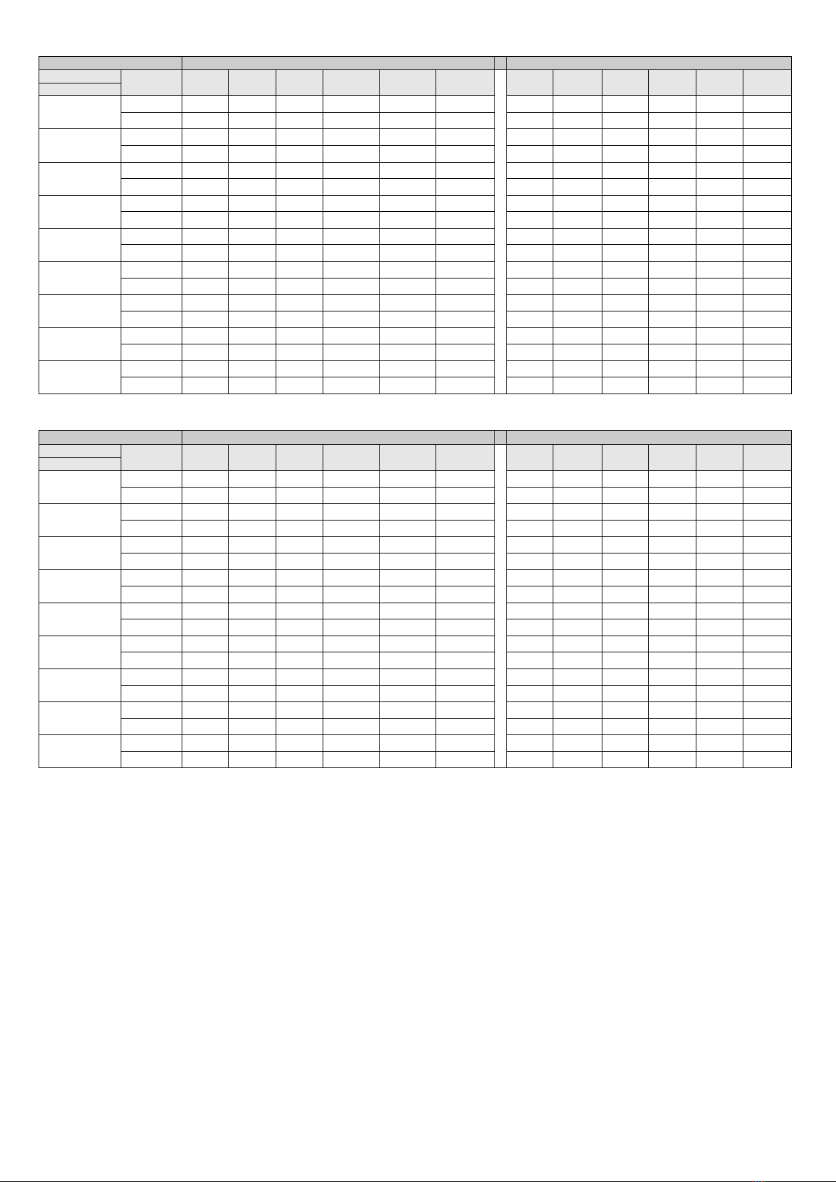
Sounder performance Volume HIGH - 80DSB
Volume HIGH
Ceiling devices -sound performance horizontal (dBA at 1m)
Ceilingdevices-soundperformancevertical(dBAat1m)
Angle
15°
45°
75°
105°
135°
165°
15°
45°
75°
105°
135°
165°
Tone
DIN 1 Hz Sweep 40V > 94 > 86 > 81 > 79 > 78 > 78 > 93 > 86 > 81 > 81 > 82 > 87
20V > 91 > 83 > 79 > 77 > 75 > 75 > 91 > 83 > 80 > 79 > 81 > 86
Dutch Slow
Whoop 40V > 95 > 87 > 83 > 82 > 80 > 80 > 94 > 87 > 82 > 81 > 84 > 87
20V
> 93
> 86
> 82
> 80
> 78
> 78
> 92
> 83
> 80
> 79
> 82
> 87
Temporal 4 40V > 98 > 90 > 87 > 85 > 80 > 84 > 97 > 89 > 84 > 84 > 88 > 92
20V > 93 > 87 > 84 > 82 > 77 > 81 > 95 > 87 > 79 > 79 > 82 > 89
BS 1 Hz Sweep 40V > 94 > 86 > 82 > 81 > 78 > 79 > 93 > 86 > 82 > 80 > 83 > 88
20V
> 92
> 85
> 81
> 79
> 77
> 77
> 91
> 83
> 79
> 79
> 82
> 86
March Time Beep
40V > 98 > 90 > 87 > 85 > 80 > 84 > 97 > 90 > 84 > 84 > 87 > 91
20V > 95 > 87 > 84 > 82 > 77 > 81 > 96 > 88 > 81 > 81 > 87 > 91
7 Hz Fast Sweep 40V > 93 > 85 > 81 > 79 > 77 > 78 > 92 > 85 > 81 > 80 > 81 > 87
20V > 91 > 83 > 79 > 77 > 76 > 76 > 90 > 82 > 79 > 78 > 80 > 86
Temporal 3 40V > 98 > 90 > 87 > 85 > 80 > 84 > 97 > 90 > 84 > 84 > 88 > 92
20V > 95 > 87 > 84 > 82 > 77 > 81 > 95 > 88 > 82 > 82 > 85 > 89
2 Tone 40V > 94 > 86 > 83 > 82 > 76 > 80 > 94 > 86 > 82 > 80 > 84 > 88
20V > 93 > 85 > 82 > 80 > 76 > 78 > 91 > 83 > 79 > 79 > 82 > 85
Continuous 970 Hz
40V > 92 > 82 > 79 > 77 > 77 > 74 > 92 > 83 > 79 > 76 > 79 > 83
20V > 91 > 79 > 77 > 75 > 75 > 72 > 90 > 81 > 79 > 75 > 79 > 83
Sounder performance Volume MID-LOW - 80DSB
Volume MID-LOW
Ceiling devices -sound performance horizontal (dBA at 1m)
Ceilingdevices-soundperformancevertical(dBAat1m)
Angle
15°
45°
75°
105°
135°
165°
15°
45°
75°
105°
135°
165°
Tone
DIN 1 Hz Sweep 40V > 73 > 66 > 61 > 61 > 62 > 67 > 74 > 66 > 62 > 61 > 63 > 68
20V > 73 > 66 > 61 > 61 > 62 > 67 > 74 > 66 > 62 > 61 > 63 > 68
Dutch Slow
Whoop 40V > 77 > 69 > 64 > 63 > 61 > 62 > 75 > 68 > 64 > 62 > 66 > 71
20V > 77 > 69 > 64 > 63 > 61 > 62 > 75 > 68 > 64 > 62 > 66 > 71
Temporal 4 40V > 80 > 72 > 67 > 66 > 62 > 65 > 79 > 71 > 66 > 66 > 69 > 73
20V > 80 > 72 > 67 > 66 > 62 > 65 > 79 > 71 > 66 > 66 > 69 > 73
BS 1 Hz Sweep 40V > 71 > 64 > 60 > 60 > 61 > 66 > 71 > 62 > 62 > 58 > 57 > 55
20V
> 71
> 64
> 60
> 60
> 61
> 66
> 71
> 62
> 62
> 58
> 57
> 55
March Time Beep
40V > 79 > 72 > 69 > 67 > 62 > 65 > 79 > 72 > 65 > 65 > 70 > 73
20V > 79 > 72 > 69 > 67 > 62 > 65 > 79 > 72 > 65 > 65 > 70 > 73
7 Hz Fast Sweep 40V > 71 > 63 > 59 > 59 > 59 > 65 > 70 > 63 > 59 > 59 > 61 > 66
20V > 71 > 63 > 59 > 59 > 59 > 65 > 70 > 63 > 59 > 59 > 61 > 66
Temporal 3 40V > 80 > 72 > 67 > 66 > 62 > 65 > 79 > 71 > 66 > 66 > 69 > 73
20V
> 80
> 72
> 67
> 66
> 62
> 65
> 79
> 71
> 66
> 66
> 69
> 73
2 Tone 40V > 72 > 65 > 59 > 59 > 61 > 66 > 73 > 63 > 61 > 59 > 57 > 56
20V > 72 > 65 > 59 > 59 > 61 > 66 > 73 > 63 > 61 > 59 > 57 > 56
Continuous 970 Hz
40V > 72 > 62 > 60 > 60 > 59 > 61 > 72 > 61 > 59 > 59 > 59 > 61
20V > 72 > 62 > 60 > 60 > 59 > 61 > 72 > 61 > 59 > 59 > 59 > 61

Installation information
Detector Base Sounder cabling
Wiring notes
All wiring must comply with local installation regulations and local fire systemdesign requirements.
Ensure all conductors are free of earths.
Verifycorrect wiring and wiring polarity before connecting the devices to the addressable loop.
Remote LEDout,wiredonlyif a remote indicator is
required
R
Not wired
M
Must not be wired
L2
Positive line in and out
L1
Optional Remote Indicator
Fig. 4: Detector Base Sounder cabling
M
R
Loop Negative
Loop Negative
L2
L
L1
Loop Positive
Loop Positive
Negative line in and out
L
Cabling
Function
Contact
Fig. 3: Detector Base Sounder dimensions
1
– Temporary park plunger
2 – Address flag holder
114
2
1
Fig. 2: Fitting the locking pin
Fig. 1: Mounting the Detector Base Sounder
A-CON
Fig 3 contains the dimensions of the Detector Base
Sounder.
These units either fit directly to the ceiling or to anoptional ceiling adaptor. See Fig 1.
See Fig2 for fitting the locking pin. To remove a detectorfrom a base with a lockingpin, complete these steps:
1
Insert a suitable toolinto the access hole to depress the locking pin in the detector cover.
2
Rotate thedetector to remove.
These unitscanbe used with the Ceiling Tile Adapter(CTA) kit (517.050.060)byusing the CTAAdaptor Plate, CTA-AP
(517.050.058).
Usethe knock outs for the cablingas required.
Dimensions
Mounting
45
50
70
For ordering, please contact Johnson Controls Customer Service in Melbourne on 1300 725 688 or[email protected]
For application or sales enquiries, please contact your local Johnson Controls sales representative.
For technical support or technical training enquiries, contact Johnson ControlsTechnical Support Centreon 1300 552 559in Australia or 09 635-0617 in New Zealand.
Further information on the extensive range of fire detection products available from Johnson Controls is available on theFireplacewebsite athttp://vigilant-fire.com.au.
Australia office: Level 3, 95 Coventry Street, Southbank, VIC 3006, Australia
New Zealand office: 17 Mary Muller Drive Hillsborough PO Box 19-545 Woolston Christchurch 8241
120.515.396.ANZ V1 ©2020 Johnson Controls. All rights reserved. All specifications and other information shown were current as of document revision date and are subject to change
without notice.
Other Vigilant Marine Equipment manuals