manuals.online logo
Brands
  1. Home
  2. •
  3. Brands
  4. •
  5. S&C
  6. •
  7. Industrial Electrical
  8. •
  9. S&C IntelliRupter PulseCloser Operator's manual

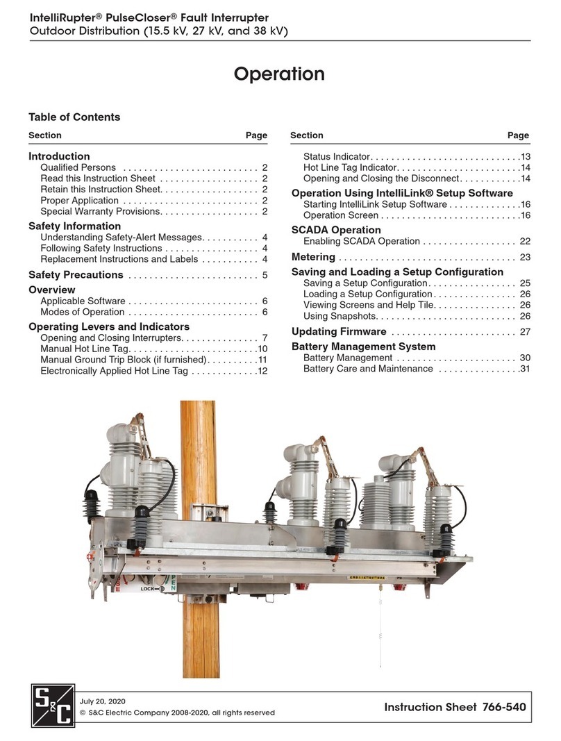
S&C IntelliRupter PulseCloser Operator's manual

Instruction Sheet 766-546
S&C Compact IntelliRupter
®PulseCloser
®Fault Interrupter Quick Operating Guide
May 1, 2017
© S&C Electric Company 2013-2017, all rights reserved
Interrupter Open/Closed
Indicator (one per pole)
Green: Interrupter open—“O”
Red: Interrupter closed—“I”
Colors are reversed on an IntelliRupter
fault interrupter furnished with Option
“-F2”
If status indicator is off:
•Supply voltage to the External Power Supply (EPS) if it is not
energized.
•If the EPS is energized, replace protection and control module.
If status indicator does not indicate
Wi-Fi connection:
•If EPS is energized, move computer at least 20 feet closer.
•Try another computer furnished with IntelliLink®Setup Software
and appropriate security keys.
•Replace communication module.
If IntelliRupter®fault interrupter does not respond to
SCADA commands:
•Enable remote operation (see “IntelliLink Setup Software
Operation—Main” screen). Remove all hot line tags and push up
on right interrupter open/close/ready lever.
•Apply local hot line tag. If IntelliRupter fault interrupter does not
send a hot line tag status point to SCADA, replace communication
module.
Lower terminal pad (X)Upper terminal pad (Y)
Interrupter Open/Close/Ready Lever
To open interrupters:
Pull down on right lever. In down position, closing is blocked.
To close interrupters:
Power must be available from the battery (if furnished) or energized
External Power Module. Remove hot line tags, if applicable. Push up
on right lever. Then pull down once on left lever for First Closing
Profile, or quickly pull down twice on left lever for Second Closing
Profile.
Pole 1 Pole 2 Pole 3
External power supply (see 766-512)
Communication
module
Hot Line Tag Lever
To manually apply a hot line tag:
Pull down on HOT LINE TAG lever.
To clear a manually applied hot line tag:
Push up on HOT LINE TAG lever.
To clear an electronically applied hot line
tag when a hot line tag has been applied
manually:
Push up on HOT LINE TAG lever. Then pull
down and push up on HOT LINE TAG lever
once, without delay.
To clear an electronically applied hot
line tag when a hot line tag has not been
applied manually:
Pull down and push up on HOT LINE TAG
lever twice, without delay.
Ground Trip Block Lever
(if furnished)
To manually apply ground trip block:
Pull down on GROUND TRIP BLOCK lever.
(When in the applied position the selected ele-
ments will be blocked or change as indicated
in the setup, see S&C Instruction Sheet 766-
530.)
To remove a manually applied GTB:
Push up on ground trip block lever. (Placing the
GROUND TRIP BLOCK lever in the up posi-
tion will not enable any elements that have not
been enabled in the active protection profile.)
Status Indicator (white LED)
Flashes for ½ second every 30 seconds:
Normal operation
Pulsates dim to bright: Wi-Fi connected
Flashes for ½ second every second:
Any Error State, or a Settings Mismatch is active
Flashes 3 times (½ second on—½ second off) every
30 seconds: Loop Restoration is timing or Ready, or
IntelliTeam is Ready
On 10 seconds, then flashes for ½ second every
30 seconds: Wi-Fi disconnected, open/close
command from interrupter open/close/ready lever,
Wi-Fi, or SCADA, or ground trip block lever moved
Solid On: Remote Operation disabled
Off: IntelliRupter fault interrupter not powered, or not
functioning properly
Protection and Control Module
Hot Line Tag Indicator
(amber LED)
Flashes for ½ second every 2 seconds:
Hot line tag applied
Off: All hot line tags removed
WARNING
IntelliRupter PulseCloser Fault Interrupter must be installed, operated, and maintained by qualified persons who are knowledgeable
in overhead electric power distribution equipment and the associated hazards. This guide is not a replacement for adequate train-
ing and experience in safety procedures for this type of equipment. Read S&C Instruction Sheets 766-510, 766-530, and 766-540
thoroughly and carefully before installing and operating your IntelliRupter PulseCloser Fault Interrupter.
2 S&C Instruction Sheet 766-546
NOTICE
To disable automatic load restoration
through the IntelliTeam®SG Automatic
Restoration System (if furnished), select:
IT SG Operation – Disabled.
To disable Loop Restoration (if furnished),
select: Loop Restoration – Disabled.
Match the location of the interrupter open/close/ready lever on the
IntelliRupter fault interrupter to the open/close/ready lever on this
screen.
•Poles are labeled left to right, configured here as A, B, and C.
•X and Y terminal designations are configurable and affect direc-
tionality. The default configuration is:
Upper terminals pads (Y1, Y2, and Y3) are labeled Y, and
Lower terminal pads (X1, X2, and X3) are labeled X.
•Voltage is shown for the three poles at each terminal pad. Phase-
to-ground voltage (1-grd, 2-grd, and 3-grd), or phase-to-phase
voltage (1-2, 2-3, and 3-1) can be selected.
•Interrupter open/close indicators match the indicators on IntelliRupter
fault interrupter, in this case they are OPEN.
•When IntelliRupter fault interrupter has tripped open, the state
of each pole is shown, for example: TESTING-SEF,LOCKOUT-
VOLTS (lockout on voltage trip), or LOCKOUT-FREQ (lockout on
frequency trip). For LOCKOUT-OC (lockout on overcurrent trip),
a lightning bolt indicates the faulted phase(s) on the side the fault
occurred. The current on each pole at the time of tripping is also
shown.
•When IntelliRupter fault interrupter is closed, load current and cur-
rent direction are shown for each pole.
•Control Status shows the status of the protection and control
module (in this case ALARM). It may also display: OK AY ,
WARNING, ERROR, MAINT MODE, or SETTINGS MISMATCH.
•Enter a Command Label, an Active Label, and an Inactive Label—for every User Command.
These will be displayed on the Operation screen. Text entered for Active or Inactive Labels
does not change their functionality.
•Ground Trip Blocked Functions—check to enable desired functionality.
•Local Battery Indication—select On if a battery is installed, then the Status Indicator on the
Control Module will flash ½ second every second when the battery is Low, Bad, or Disconnected.
If no battery is installed, select Off.
•Remote Off Indication—the Status Indicator on the Control Module can be configured to display
solid on when Remote Operation is disabled.
•Connected to: and Location:—at the top of the screen, show the name and address of the
IntelliRupter fault interrupter connected through IntelliLink or IntelliLink Remote software.
•Disconnect shows the position of the visual disconnect: OPEN,
CLOSED, or Not Installed.
•Loop Restoration or Communication Enhanced Coordination
status is displayed when when either feature is furnished and
Enabled.
•OPEN and CLOSE buttons trip and close the interrupters. A single
phase can be operated if Single Phase Operation is Active.
•Single Phase Operation, Ground Trip Block, and Test on
Backfeed can be enabled or disabled.
•Hot Line Tag can be enabled or disabled, and the application
method is indicated.
•Circuit Testing, and Sensitive Earth Trip can be enabled or
disabled.
•Clear Latched Overcurrent can be executed.
•Active General Profile and Active Closing Profile can be
selected.
•Remote Operation can be enabled or disabled.
•IT SG Restoration can be enabled or disabled.
•Connected to: and Location:—at the top of the screen, show the
name and address of the IntelliRupter fault interrupter connected
through IntelliLink or IntelliLink Remote software.
IntelliLink Setup Software: Setup—General—User Commands ScreenIntelliLink
®Setup Software: Operation Screen
NOTICE
Refer to S&C Instruction Sheet 766-530
for detailed information about IntelliRupter
fault interrupter configuration.
Other manuals for IntelliRupter PulseCloser

4

Other S&C Industrial Electrical manuals

S&C TripSaver II Owner's manual

S&C

S&C TripSaver II Owner's manual

S&C IntelliRupter PulseCloser User manual

S&C

S&C IntelliRupter PulseCloser User manual

S&C Scada-Mate SD Owner's manual

S&C

S&C Scada-Mate SD Owner's manual

S&C Vista Series User manual

S&C

S&C Vista Series User manual

S&C Mark VI Guide

S&C

S&C Mark VI Guide

S&C PMH Series Instruction Manual

S&C

S&C PMH Series Instruction Manual

S&C Vista SD User manual

S&C

S&C Vista SD User manual

S&C TripSaver II User manual

S&C

S&C TripSaver II User manual

S&C IntelliRupter PulseCloser User manual

S&C

S&C IntelliRupter PulseCloser User manual

S&C TripSaver II User manual

S&C

S&C TripSaver II User manual

S&C IntelliRupter PulseCloser User manual

S&C

S&C IntelliRupter PulseCloser User manual

S&C TripSaver II Quick guide

S&C

S&C TripSaver II Quick guide

S&C IntelliRupter PulseCloser Fault Interrupter Instruction Manual

S&C

S&C IntelliRupter PulseCloser Fault Interrupter Instruction Manual

S&C TripSaver II Quick guide

S&C

S&C TripSaver II Quick guide

S&C TripSaver Owner's manual

S&C

S&C TripSaver Owner's manual

Popular Industrial Electrical manuals by other brands

Murata GRM21B5C1H223JA01 Series Reference sheet

Murata

Murata GRM21B5C1H223JA01 Series Reference sheet

IME RD1G0 manual

IME

IME RD1G0 manual

Murata GRM1887U1H752JA01 Series Reference sheet

Murata

Murata GRM1887U1H752JA01 Series Reference sheet

Moeller A-NZM 10 installation instructions

Moeller

Moeller A-NZM 10 installation instructions

Herman Miller Locale Modular Electrical Installation and Disassembly

Herman Miller

Herman Miller Locale Modular Electrical Installation and Disassembly

Haufftechnik HSI150 DG installation instructions

Haufftechnik

Haufftechnik HSI150 DG installation instructions

Delta DT-2000 Series Operation manual

Delta

Delta DT-2000 Series Operation manual

red lion VT-IPm2m-***-D Series Installation and maintenance manual

red lion

red lion VT-IPm2m-***-D Series Installation and maintenance manual

Sunway PowerTap GMPT-1 Assembly instructions

Sunway

Sunway PowerTap GMPT-1 Assembly instructions

Murata GRM185C81A475ME11 Series Reference sheet

Murata

Murata GRM185C81A475ME11 Series Reference sheet

Murata GRM21BR61E225KA12 Series Reference sheet

Murata

Murata GRM21BR61E225KA12 Series Reference sheet

Murata GRM0335C1E130GA01 Series Reference sheet

Murata

Murata GRM0335C1E130GA01 Series Reference sheet

Murata GRM31MR72A474KA35 Series Reference sheet

Murata

Murata GRM31MR72A474KA35 Series Reference sheet

Murata GRT21BC80G476ME13 Series Reference sheet

Murata

Murata GRT21BC80G476ME13 Series Reference sheet

nvent Raychem JBU-100-E Installation instruction

nvent

nvent Raychem JBU-100-E Installation instruction

Murata GRM1557U1A152JA01 Series Reference sheet

Murata

Murata GRM1557U1A152JA01 Series Reference sheet

Murata GQM1885C1H680GB01 Series Reference sheet

Murata

Murata GQM1885C1H680GB01 Series Reference sheet

Fritsch 16.60 0 Series operating instructions

Fritsch

Fritsch 16.60 0 Series operating instructions

manuals.online logo
manuals.online logoBrands
  • About & Mission
  • Contact us
  • Privacy Policy
  • Terms and Conditions

Copyright 2025 Manuals.Online. All Rights Reserved.