Sanden GAUS-315EQTA User manual

SandenHeatPump–InstallationManual
Page1of26
Covering model numbers
GAUS-315EQTA
GAUS-315EQTB
GAUS-315EQTC
HeatPumpUnitGAU‐A45HPA
TankUnitHP315SSA_D.2
TankUnitHP315SSA_C.2
TankUnitHP315SSA_F.0
TankUnit
GAU‐315EQTA

SandenHeatPump–InstallationManual
Page2of26
Contents
Contents..............................................................................................................................................................................2
Introduction......................................................................................................................................................................3
Howitworks.....................................................................................................................................................................3
Installationdetails..........................................................................................................................................................4
Installationlocation.......................................................................................................................................................5
Powerrequirement........................................................................................................................................................6
PipingConnections........................................................................................................................................................7
Heatpumpunitpiping..................................................................................................................................................8
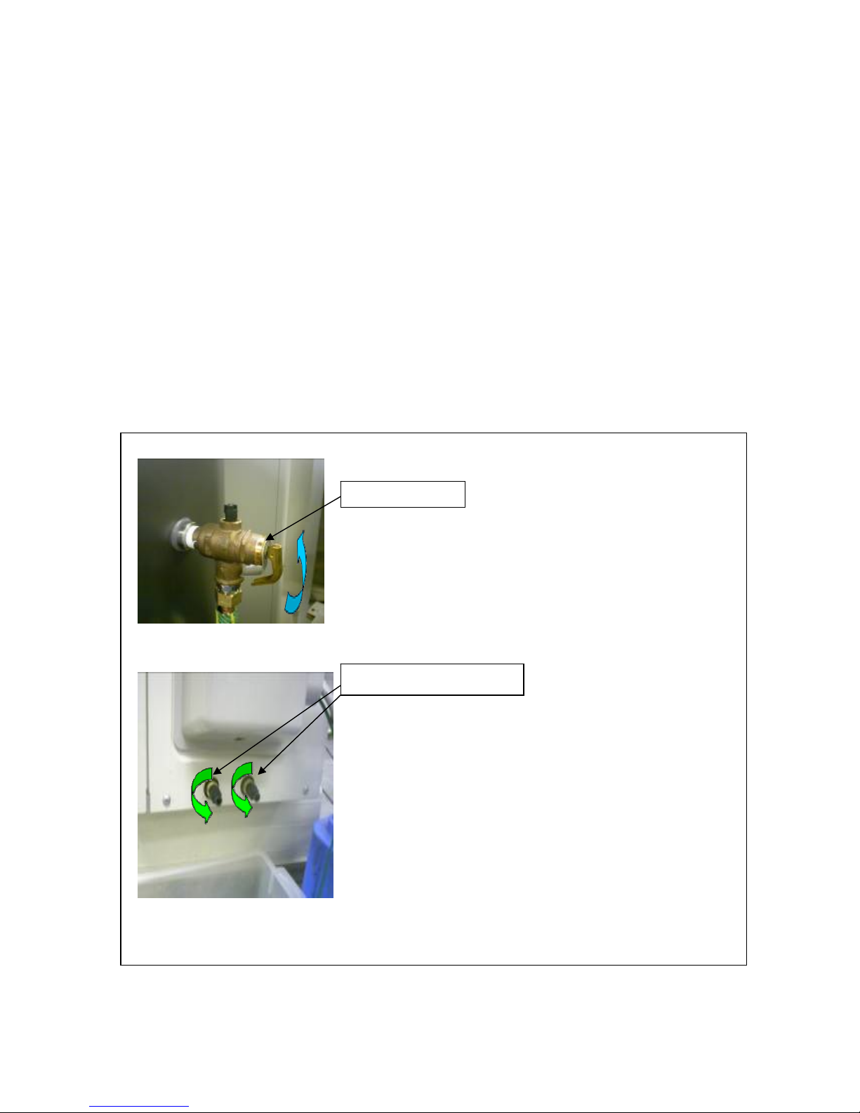
Removingairfromthesystem..................................................................................................................................9
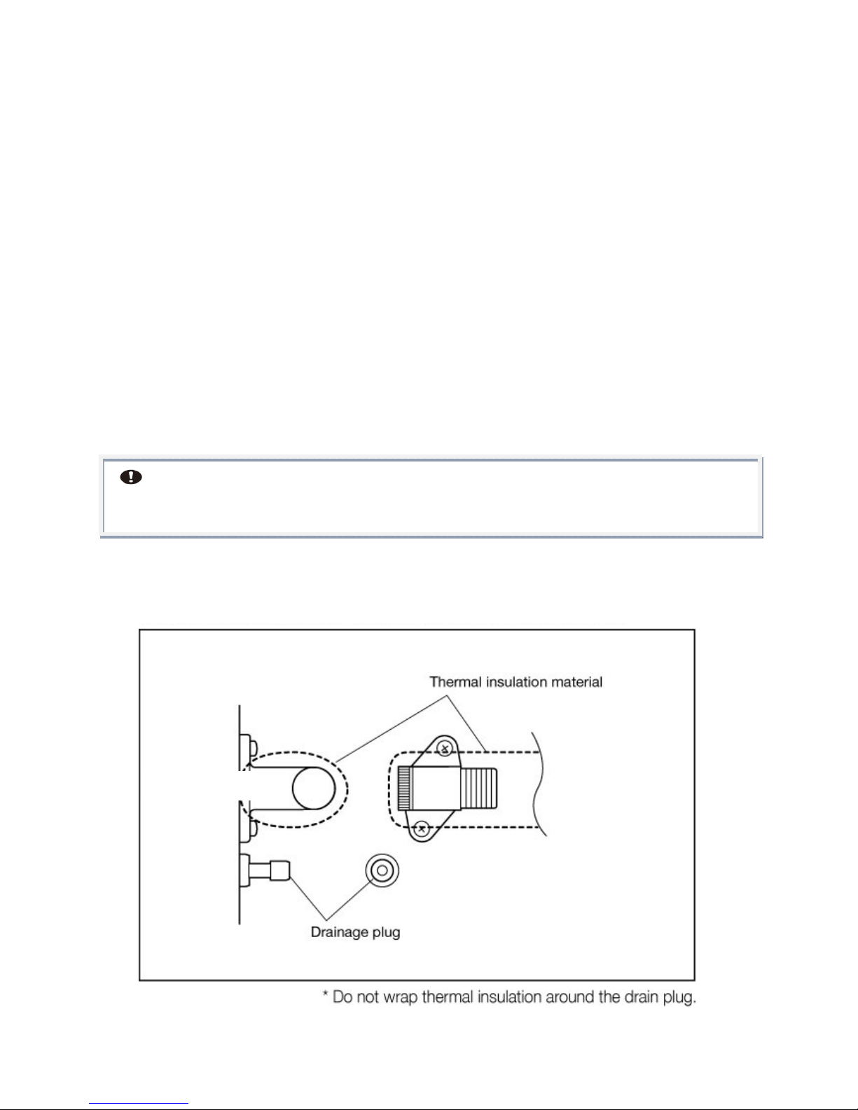
Freezeprotection.........................................................................................................................................................10
Electricalconnections................................................................................................................................................11
Systemoperationoutlinecontinuouspower..................................................................................................11
Systemoperationifconnectedtooff‐peakelectricity.................................................................................11
Howtoconnecttankunitthermistorcable......................................................................................................13
Timesettingandblockouttimesetting............................................................................................................14
Blockouttimesettingmode....................................................................................................................................15
MaintenanceMode......................................................................................................................................................16
HowtoswitchtoMaintenanceMode..................................................................................................................16
ErrorCodes....................................................................................................................................................................17
Changeofwatersupply.............................................................................................................................................19
Dimensionsandtechnicaldata..............................................................................................................................20
WarrantyPolicy............................................................................................................................................................23
WarrantyPeriod..........................................................................................................................................................24
Postinstallationinspectionchecklist.................................................................................................................24
Checksheet.....................................................................................................................................................................25
Memo.................................................................................................................................................................................26
Warranty.........................................................................................................................................................................25
PATENTS
This water heater may be protected by one or more patents or registered designs
in the name of Sanden Australia Pty Ltd
TRADE MARKS
® Registered trademark of Sanden Australia Pty Ltd
.
Note: Every care has been taken to ensure accuracy in preparation of this publication.
No liability can be accepted for any consequences that may arise as a result of its application

SandenHeatPump–InstallationManual
Page3of26
Introduction
The Sanden Heat Pump Water Heater System has been designed using the latest
refrigeration technology to remove the heat from the air to heat water. The refrigerant we
use is CO2 which does not contribute to global warming so it allows us to help keep a clean
healthy earth for future generations.
We have also considered the power requirement. By using CO2 as the refrigerant we have
produced one of the most energy efficient units currently available. It’s even more efficient
when connected to off-peak power1 and the noise level is so low it will operate
unobtrusively throughout the night.
Howitworks
The Heat Pump Water Heater System heats water by transferring the heat from the
surrounding air to the water using a refrigerant. The refrigerant is heated by a heat
exchanger that absorbs heat from the surrounding air (Figure 1).
Figure 1: Heat Pump Water Heater System
Note1 operating conditions may vary depending on the type of off peak tariff that is available in
your area. The unit must have a minimum of 5 hours continuous power available
Heat pump unit Tank unit (hot water storage)

SandenHeatPump–InstallationManual
Page4of26
Installationde ta i ls
This Heat Pump Water Heater System must be installed by a licensed person in
consideration of the following standards and regulations:
AS/NZS3500 National plumbing and drainage code hot water supply systems –
acceptable solutions
HB 263-2004 Heated water systems plumbing industry commission
AS/NZS 3000 Electrical installations (known as the Australian/New Zealand wiring
rules)
Notice to Victorian customers from the Victorian Plumbing Industry Commission.
The Victorian Building Act 1993 requires that this Heat Pump Water Heater System
must be installed by a licensed person. Only a licensed person will provide a
Compliance Certificate, showing that the work complies with all the relevant
standards. Only a licensed person will have insurance protecting their workmanship
for six years.
The unit has been specifically designed for domestic hot water heating and is not
suitable for any other purpose.
The unit is designed to operate when connected to the town water supply with a
maximum operating pressure of 650 kPa. To ensure the mains pressure does not
exceed this, a pressure-limiting device that complies with AS1357 must be
connected to the town water supply line.
This system delivers hot water exceeding 50o C. Reference should be made to
AS/NZ3500 and/or local regulations relating to the need for temperature tempering
devices.
The unit must be stored and transported in an upright position. Failure to do so may
render the unit faulty. Such failure is not covered under any warranty agreements.
Failure to comply with the above conditions will void the warranty.
Figure 2: Typical installation layout

SandenHeatPump–InstallationManual
Page5of26
Installationlo c a ti o n
For the most efficient operation of the heat pump unit the optimum location is the
warmest side of the property and there should be sufficient space for the warm air
to circulate through the unit.
The tank unit should be located as close as possible to the most frequently used hot
water outlet such as a bathroom. It may be located either outside or inside. The
heat pump unit must be located outside and as close as practicable to the tank unit
but not further than four meters away from it.
Ensure sufficient clearance around the heat pump unit to allow air to circulate and
provide adequate space for service maintenance of the unit (Figure 3).
Although the heat pump unit is very quiet it is preferable to avoid installing it directly
below a bedroom window.
Install the heat pump unit in an area which allows sufficient ventilation. Poor
ventilation may cause the unit to short cycle and this could increase the power
consumption by more than 10%.
Do not install the heat pump unit in a confined space.
If the heat pump unit is installed facing a wall, exhaust air may stain the wall.
Figure 3: Restrictions on where the heat pump unit can be installed (overhead view)
Flat wall installation
Corner installation

SandenHeatPump–InstallationManual
Page6of26
Figure 4: Restrictions on installation with the space between the tank unit and the
heat pump unit
gure4
Powerrequirement
The power requirement for the system is a dedicated 17 amp circuit fitted with a
circuit breaker. This circuit may be connected to constant power or off-peak.
Installation of this system must be carried out only by a qualified installation
technician (electrical or plumbing).
The surface to which the heat pump unit is installed must be firm, preferably a
concrete pad or block. If the surface is firm there is no need to fix the unit to a base
surface, unless there is a likelihood of high wind or local vibration. If the heat pump
unit and tank unit are fixed, appropriate fixing devices should be used.
A pressure and temperature relief (PTR) valve is included in the installation kit of
the tank unit. This is installed in a defined point near the top of the tank unit. The
PTR valve must have a clear space where escaping steam or water can flow freely.
The installation site must be well drained so that any water accumulating (such as
local rain or pipe leakage) will drain away and not enter the heat pump unit and the
tank unit.
Local water pressure must be a minimum of 200 kPa to ensure efficient functioning.
Note: The entire system is set up and fully functional when supplied. Once all the water
and electric connections have been made the system finds the right timing to run the water
heating cycle automatically as long as the electricity is available. The only adjustment
required is the current time setting on the timer setting panel under the top housing cover,
especially if the blockout time setting is desired. See current time setting and blockout time
section on page 14.
Total piping length: 4 metres maximum
per way
Number of bends: 6 maximum
Keep the piping run to a minimum as
the longer the pipe run the greater the
potential for heat loss.
Side view
Overhead view
Standard la
y
out
(A) Difference in height
between the base of tank and
base of Heat pump should be
no more than: 3m Max.

SandenHeatPump–InstallationManual
Page7of26
Figure 5: Heat pump installation example and dimensions
Attach the drain elbow to the drain opening located on the bottom of the heat pump
unit. The drain elbow is included in the installation kit for the heat pump unit.
Attach a drain hose with 16mm of inner diameter to the drain elbow to guide the
drained water to a appropriate drain
PipingConnections
All piping that connects to the water supply must be carried out by a licensed plumber.
The water supplied to the system must comply with the drinking water quality standard.
Use of water that does not comply with this standard could result in a malfunction of
the system.
The water source must have a pressure of 200 kPa or higher.
A drain hopper must be installed under the drain outlet.
A drain trap must be installed over the drain pipe if water is to be drained to a drain
ditch. If a drain trap is not installed gas could flow out and cause severe corrosion and
malfunction of the heat pump unit.
This product cannot be connected to a solar water heater.
The piping must be appropriately insulated.
If the piping needs brazing make sure that all flux and flux splatter is wiped away with a
wet cloth.
As the hot-water supply pipe will expand and contract use sleeves when passing it
through concrete walls or slabs.
With buried piping a sheath pipe will need to be used that has had both ends sealed to
avoid any rain penetration.
Use only heat-resistant and corrosive-resistant material to seal the pipe joints.
Cutting and wrenching the piping material may result in oil and dust adhering to it. After
processing, clean the material with a mild detergent before doing any piping work and
smooth the edges to remove any scratches and burrs. (After passing water through it
verify whether any dust has accumulated on the filter of the taps and heat pump unit
pipe.)
When using sealing tape ensure that no tape is sticking out of the thread.
If any heat-resistant vinyl chloride pipes (such as HT pipe) are bonded together, pass
water through them after the pipes have set to prevent any bond adhering to the filter
or other parts.

SandenHeatPump–InstallationManual
Page8of26
Follow the manufacturer’s instruction manual for the type of bond, amount to be
applied, curing time, and other specifications. If any bond or flux has entered the tank
unit and the hot water has a chemical/acrid smell take the following countermeasures.
a) After heating the water in the tank unit, drain it and clean inside the tank unit. Fill the
tank unit with 100 litres of water and exchange twice.
b) Clean or change the filter.
c) Fill up the tank unit.
d) Drain water from the relief valve for one to two minutes.
e) Run water from all the hot water supply taps in the house for about ten minutes to
clean inside the pipes.
Heatpumpunitpiping
Connect the heat pump unit cold supply to the tank unit fitting marked Cold Supply.
Connect the heat pump unit hot return to the tank unit fitting marked Hot Return.
Connect the mains water supply to the lower fitting on the tank unit marked Cold Water
Inlet.
Connect the hot water supply pipe to the top of the tank unit marked Hot Water Outlet.
Install the supplied PTR valve to the fitting on the tank unit marked PTR valve.
Pass water through the pipe to remove any dust inside before connecting the pipe.
After all the piping connections are completed, pass water through the system.
Close the stop valves (four places) and detach the filter on the cold supply connector
of the heat pump unit to confirm there is no object that blocks the filter. Clean the filter
if any blockage.
Remove the air from the system according to the instructions below.
Make sure all the necessary devices are mounted to the pipes as shown in diagram. If
the heat pump unit piping is crushed or clogged or the air inside was not removed
during the test operation, temperature of the supplied hot water may become
inconstant.
Figure 6: System piping

SandenHeatPump–InstallationManual
Page9of26
Removingairfromthesystem
The following steps must be taken to ensure all air is removed from the system.
Incorrect removal of air may cause the water temperature to vary.
Plumb pipes to tank unit and heat pump unit.
Push up the lever on the PTR valve to open, and fill the tank unit with water.
Confirm the water comes out of the relief valve and then close the lever.
Open the water tap to remove air.
Close the tap after no air is confirmed in the water.
Open the water drain plugs (two places) on the heat pump unit.
Close the plugs after no air is confirmed in the water.
Supply the power to the heat pump unit and leave the water tap open for three
minutes.
Close the tap after no air is confirmed in the water.
Figure 7: Air removing process
Plumb pipes to Storage Tank Unit and Heat Pump Unit.
Push up the lever on the PTR valve to open,
and fill in the tank with water.
Confirm the water come out of the relief valve,
and then close the lever.
Open the water tap to remove air. Close the tap after no
air is confirmed in the water.
Open the water drain plugs (2 places) on the Heat Pump
Unit.
Close the plugs after no air is confirmed in the water.
Supply the power to the Heat Pump Unit and leave the
water tap open for 3 minutes.
Close the tap after no air is confirmed in the water.
Water drain plugs
PTR valve

SandenHeatPump–InstallationManual
Page10of26
Freezeprotection
Even if the pipes have been insulated, the piping can freeze if the surrounding
temperature gets below zero. This could cause damage to the equipment and
piping so make sure the appropriate freeze protection measures are taken
Follow the instructions in the installation manual provided with the freeze protection
heater.
After completion of the piping work inspect the plumbing for any water leaks from
the joints before carrying out freeze protection.
Wrap the freeze protection heater up to the water connectors of the main unit.
Ensure the freeze protection heaters are connected to 24 hours continuous power
supply..
It is important to fully explain how to use and operate the freeze protection heater to
the customer.
When turning off the power because the unit will not be in use, any water must be
removed from the unit and piping.
.
Note A heater that checks the outside temperature may not detect the temperature
of the piping correctly. It is important to use a heater that directly detects the piping
temperature.
Figure 8: Details on wrapping thermal insulation around the piping connector

SandenHeatPump–InstallationManual
Page11of26
Electricalconnections
Electrical installation should be done only by a licensed electrician who carries out
the work according to the relevant regulations for electrical safety and wiring.
Follow the wiring rules for the breaker rating and the thickness of the electrical
wiring.
Verify that the tank unit is full of water and the water stop cocks are open before
turning on the power.
Systemoperationoutlinecontinuouspower
The system runs its water heating cycle once a day to fill up the storage tank unit with
heated water.
If the block out time function is selected ( setting is covered in page 14 ) the unit will
not operate during the block out times – this function is typically used on installations
that have time of use electricity tariffs
The water heating cycle operation starts automatically when the residual hot water in
the tank unit becomes less than 150 litres.
The system will not run if the electrical power supply is cut off (i.e. if it is connected to
off-peak power). However, the system will automatically start operation, once the
electricity becomes available.
Systemoperationifconnectedtooffpeakelectricity
There are no special settings for the off-peak connection. The system will run once the
power becomes available and the temperature in the tank drops below the set point of
the tank thermister. If connecting the unit to off peak ensure that the off peak tariff
provides a minimum of 5 hours continuous power, as it can take at least four hours to
fill the tank unit with hot water if the ambient temperature is lower than 10oC this can
be longer.
If the unit is connected to off peak and consumption has been higher than normal hot
water might not be available until the next power supply cycle.
Daily frequency and amount of hot water consumption may also affect the duration of
the heating cycle operation.
Select the electrical supply mode that best suits the customer’s hot water consumption. The
type of off-peak connection may need to be changed if hot water supply is not maintained as
required.
Figure 9: Outline of electrical system connections

SandenHeatPump–InstallationManual
Page12of26
Electrical installation should only be done by a licensed electrician
How to connect power line
Remove the piping cover, terminal block cover and screw clamp fitting.
Connect the power supply line to the terminal block.
Hold the power supply line below the terminal block with the screw clamp fitting.
Attach the terminal block cover and piping cover back on the heat pump unit.
Figure 10: Connect power cables
Outlineofelectricalsystemconnections

SandenHeatPump–InstallationManual
Page13of26
Howtoconnecttankunitthermistorcable
Cut the thermistor cable and conduit to the required lengths. The thermistor cable and
conduit length are designed to cover the maximum allowable distance between the
tank unit and heat pump unit (four meters). If the units are located closer than four
meters the thermistor cable and conduit may be cut to the desirable length (Figure 11).
Reveal the sheath on the thermistor cable.
Attach the conduit connector to the conduit end. Push the conduit into the opening on
the connector until the conduit does not go any further. Pull the conduit several times
to ensure the connector is fixed properly to the conduit.
Unscrew and firmly remove the terminal block cover. Do not use unnecessary force to
remove the cover as this could pull and break the cable coming out of the tank unit.
Join the connector on the end of the thermistor conduit coming from the heat pump
unit side to the opening on the bottom of the cover on the tank unit. Confirm the gasket
is attached to the tread of the conduit connector before joining the connector to the
cover. If the gasket is not attached, there is a risk of water getting inside the cover and
this may result in a malfunction of the terminal block.
Connect the thermistor cable to the bottom of the terminal block.
Put the terminal block cover back onto the tank unit and tighten the screws.
Figure 11: Connect tank unit thermistor cable
Gasket
Conduit
connecto
Conduit
Thermister
cable
Terminal
block
Tankunit

SandenHeatPump–InstallationManual
Page14of26
Timesettingandblockouttimesetting
Currenttimesetting
This product contains a built-in clock IC. As a part of the water heating cycle logic refers to the current time,
it is necessary to set the clock before starting to use the product. The current time can be set in the Clock
Setting Mode as described below.
*Note
There is no need to adjust the time setting for the daylight saving period. Even if the installation is
conducted during the daylight saving period, the clock setting to the ordinary time (not daylight
saving time) is preferable.
1. Switching to Clock Setting Mode
Press the “Enter” key in the Clock Display Mode to switch to the Clock Setting Mode. Time Display
starts flashing once the mode is switched.
2. Setting the Clock
The time setting can be adjusted by pressing “Up” and “Down” keys. Fast forward and rewind are
available by pressing and holding down a key.
3. Executing Setting the Clock
After the clock is adjusted to the current time, press the Enter key to execute the setting. The time
display stops flashing and comes on once the setting is finished.
*Caution
The display automatically goes back to the Clock Display Mode when no panel operation is
performed for more than 60 seconds in the Clock Setting Mode. If this occurs, changes made will
not be reflected to the setting. If the clock setting is rewound to a time that is earlier than the time
when a heating cycle is triggered, the system will start the heating cycle.
*Note When no panel operation is performed for more than 60 seconds the display is switched to the
Display Sleep Mode and turns off. Display Sleep Mode is cancelled when Up, Down or Enter key is
pressed.
Figure 12 Maintenance mode
Enter
Button
Up/Down Buttons
Display
Window
LED Status
Window

SandenHeatPump–InstallationManual
Page15of26
Blockouttimesettingmode
This mode is used to set the block out time that blocks the heat pump unit operation within
the setting time.
Blockout times are used if the customer has a time of use tariff.
Change the mode
Press and hold down Up and Down keys together in the clock display mode to go to
the block out time setting mode. Once the mode is changed, ‘bo’ and ‘00XX’ (00 =
start time, XX = end time) are displayed. (Initial setting = 00 o’clock for both start
and end)
Adjust set block out start time
Press Up or Down key and ‘00’ (start time) in ‘00XX’ starts flashing and ‘XX’ (end
time) illuminates. Now the block out start time can be adjusted. Setting can be
performed only in hour increments, not in minutes.
Set block out start time
Press the Enter key to set the desired time setting. After the start time is set, the
start time display stops flashing. The end time display starts flashing at the same
time.
Adjust block out end time
Set to the desired end time by using Up and Down keys. Setting can be performed
only in hour increments, not in minutes.
Set block out end time
Press enter key to adjust the desired time setting. After the end time is set, the
start time and end time are displayed for two seconds, then it starts to display ‘bo’
and ‘00XX’ (00 = start time, XX = end time) by turns.
Go back to clock display mode
Press Enter key to go back to the clock display mode. It will automatically go back
to the clock display mode when no panel operation is performed for more than 60
seconds. Blockout time setting mode cannot be set unless the end time setting is
executed.
Cancel block out setting
To cancel the block out setting, set both start and end times to ‘00’. Setting to other than
‘00’ (01 ~ 23) will be interpreted as a setting error and the end time will flash. Make sure to
set both times to ‘00’ when cancelling the block out time setting

SandenHeatPump–InstallationManual
Page16of26
MaintenanceMode
Maintenance mode is a function to check the heat pump unit status and to check and
perform other settings. It should generally be assumed that the owner does not operate
this function. The following modes can be found in the maintenance mode.
Blockout time setting mode
Set the block out time.
Error history display mode
Check the history of any errors that may have occurred.
Parameter display mode
Check the values measured by the thermistor.
Drive setting mode: Switch the heat pump unit on/off.
Compulsory operation mode: Compulsorily operate the water heating cycle.
Pump remote operation mode: Run the water circulation pump.
HowtoswitchtoMaintenanceMode
Press and hold down Up and Down keys together in the clock display mode to go to the
maintenance mode. After the mode is switched, press the Enter key to select a mode from
the six modes described above. To finish the maintenance mode, press and hold down
the Enter key, or leave for more than 60 seconds with no panel operation.
Change: Hold down ‘Up’ and ‘Down’; No operation for 60 seconds (delete min.?) – this change needs to
be done in three places.
Figure 13 Maintenance mode diagram
Dis
p
la
y
Slee
p
Mode
ClockDisplayMode
ClockSettingMode
ErrorHistor
y
Dis
p
la
y
Mode
ParameterDis
p
la
y
Mode
BlockoutTimeSettin
g
Mode
DriveSettin
g
Mode
Com
p
ulsor
y
O
p
erationMode
Enter
Enter
Enter
Enter
Enter
Enter
AnyKey
EnterEnter
or
NoOperation
for60secmin.
NoOperation
for60secmin.
Holddown“UP”
and“DOWN”
tth
Enter
or
NoOperation
for60secmin.
PumpRemoteOperationMode

SandenHeatPump–InstallationManual
Page17of26
ErrorCodes
When an error has occurred, a red LED on the timer setting panel turns on and an error
code is displayed on the LED display. The panel does not turn to the display sleep mode
while the error code is shown.
After a component is replaced or the inspection is completed, turn the breaker on/off
several times to confirm the error does not re-occur.
Below is the list of the error codes. If the corrective action does not solve the error problem,
a malfunction of the PCB valve is highly likely.
Error
code
Errorcontents
Correctiveaction
E000 No error generated
E010 HP inlet temperature thermistor wire
break
Check the thermistor connectors on the
main PCB in the heat pump unit for any
disconnection, fall-off, wire breakage or
short circuit
E011 HP inlet temperature thermistor
short circuit
E012 HP outlet temperature thermistor
wire break
E013 HP outlet temperature thermistor
short circuit
E014 HP ambient temperature thermistor
wire break
E015 HP ambient temperature thermistor
short circuit
E016 HP defrost temperature thermistor
wire break
E017 HP defrost temperature thermistor
short circuit
E018 HP discharge temperature
thermistor wire break
E019 HP discharge temperature
thermistor short circuit
E020 Tank thermistor a wire break
E021 Tank thermistor a short circuit
E040 HP water outlet over temperature 1 - Check the heat pump piping filter for
any blockage
- Check for any piping bend, blockage or
crush
- Inspect for frozen pipes
- Open the valve on water mains
- Open the stop valves
- If the water circulation pump is not
moving, replace the pump
E041 HP water outlet over temperature 2
E042 HP outlet temperature thermistor
detection error - Check if the thermistor is off the
mounting pocket on the water outlet pipe
E043 HP discharge over temperature 1 - Replace the discharge temperature
thermistor
E044 Hp discharge temperature

SandenHeatPump–InstallationManual
Page18of26
Notes:
1. After a component is replaced or the inspection is completed, turn the unit on/off
several times to confirm the error does not re occur.
2. If the corrective actions above do not solve the error problem, a malfunction of the
PCB is highly likely.
Thermistor detection error
- Reconnect the expansion valve
connector, check if it is off the PCB
- Replace the expansion valve (together
with PCB), or the entire unit of heat
pump
E045 HP defrost thermistor detection error - Check if the thermistor is mounted in
position on the evaporator
- Replace the defrost thermistor
E047 High pressure side error
- Check the heat pump piping filter for
any blockage
- Check if any piping bend, blocking or
crush
- Inspect if the pipes are being frozen
- Open the valve on water mains
- Open the stop valves
- If the water circulation pump is not
moving, replace the pump
E048 High ambient temperature defrost
drive error
- Remove foreign objects from the
evaporator (e.g. fallen leaves, grass,
snow)
- Replace the ambient temperature
thermistor
- Replace the defrost thermistor
E070 Fan motor locked - Reconnect the connector, check if it is
off the PCB
- Replace the fan motor
E071 Fan motor revolution error
E073 Water circulation pump locked
- Check for heat pump piping block and
crush
- Confirm that the connector on the
water circulation pump cable sitting on
the PCB properly
- Replace the water circulation pump
E090
~
E150 System control error Replace the PCB

SandenHeatPump–InstallationManual
Page19of26
Water Supply Quality
Chloride and pH
In high chloride water supply areas, the water can corrode some parts and cause them
to fail. Where the chloride level exceeds 250 mg/litre warranty does not apply to the
heat pump unit and tank unit. pH is a measure of whether the water is alkaline or acid.
In an acidic water supply, the water can attack the parts and cause them to fail. No
warranty applies to the heat pump unit and tank unit where the pH is less than 6.0. The
water supply from a rainwater tank unit in a metropolitan area is likely to be corrosive
due to the dissolution of atmospheric contaminants. Water with a pH less than 6.0 may
be treated to raise the pH. It is recommended that an analysis of the water from a
rainwater tank be conducted before connecting this type of water supply to the system.
Figure 14
Changeofwatersupply
Changing, or alternating, from one water supply to another can have a detrimental
effect on the operation and/or life expectation of the water tank unit cylinder, PTR valve,
water heating circulation and the heat exchanger in the system. Where there is a
changeover from one water supply to another, for example, a rainwater tank supply,
desalinated water supply, public reticulated water supply or water brought in from
another supply, then water chemistry information should be sought from the supplier or
the water should be tested to ensure it meets the warranty requirements in this
installation manual.

SandenHeatPump–InstallationManual
Page20of26
Dimensionsandtechnicaldata
HotwaterstoragetankunitGAU‐315EQTA
Storagecapacity315litres
Productweight 82kg
Designpressure700kPa
StoragetankmaterialStainlesssteel
OutsidecasingColourcoatedzincsteel
Other manuals for GAUS-315EQTA
1
This manual suits for next models
6
Table of contents
Other Sanden Heat Pump manuals
Popular Heat Pump manuals by other brands

Thermia
Thermia Atlas installation guide

Dantherm
Dantherm HPP-iw Series Owners & installation manual

Daikin
Daikin ERGA06EAV3H Installer's reference guide

Hitecsa
Hitecsa EKWXBA HE 38.2 Installation, operation & maintenance manual

Sensa-Heat
Sensa-Heat ES Series user manual

Bosch
Bosch FHP EC Large Series Installation, operation and maintenance manual