Table of Contents
Table of Contents
Chapter 1. Introduction
...................................................................................................... 1
1.1 What is CANopen?.......................................................................................................................... 1
1.2 What are the Benefits of Using the CANopen Option Board?......................................................... 1
1.3 Components..................................................................................................................................... 1
Chapter 2. CANopen Communication Option
......................................................................... 2
2.1 Technical Data of CANopen Communication Module ..................................................................... 2
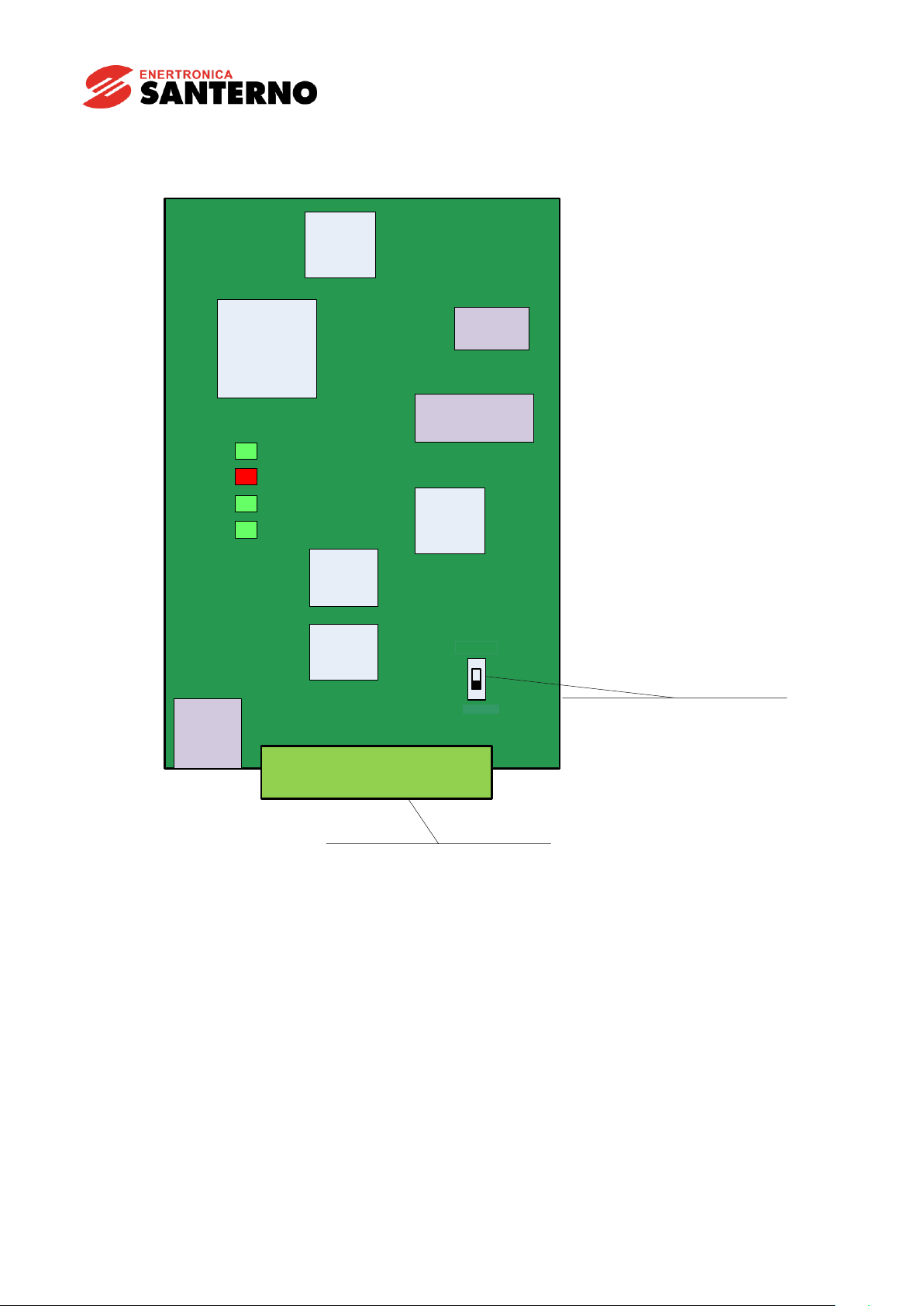
2.2 Layout of CANopen Communication Module .................................................................................. 3
2.3 Installation of CANopen Communication Module............................................................................ 4
2.4 Connection of connector for CANopen signal line........................................................................... 6
2.5 Hardware installation ....................................................................................................................... 7
2.6 Maximum Communication Range according to Baud Rate........................................................... 10
Chapter 3. Diagnosis of the Option Statuses and LED Definition
...............................................11
3.1 Definition of the LED Signal............................................................................................................11
3.2 Diagnosis of Option by LED Signal ................................................................................................11
Chapter 4. Data Communication Protocol of the CANopen
.......................................................17
4.1 Communication Protocol of the CANopen..................................................................................... 17
4.1.1 CAN-ID................................................................................................................................... 17
4.1.2 SDO communication.............................................................................................................. 18
4.1.3 PDO communication.............................................................................................................. 18
4.2 NMT (Network Management) State Machine ................................................................................ 20
4.2.1 NMT state initialization........................................................................................................... 21
4.2.2 NMT state Pre-operational..................................................................................................... 22
4.2.3 NMT state operational............................................................................................................ 22
4.2.4 NMT state stopped................................................................................................................. 22
4.2.5 The frames enabling communication by NMT status............................................................. 23
4.3 Error Control Protocols.................................................................................................................. 23
4.3.1 Protocol node/life guarding .................................................................................................... 23
4.3.2 Protocol heartbeat.................................................................................................................. 24
4.3.3CANopen EDS File ................................................................................................................ 24
Chapter 5. Detailed Specification of Communication Profile Specific Objects
................................25
5.1 Device Type................................................................................................................................... 25
5.2 Error Register ................................................................................................................................ 25
5.3 Pre-defined Error Field .................................................................................................................. 27
5.4 COB-ID SYNC Message................................................................................................................ 28
5.5 Manufacturer Device Name........................................................................................................... 28
5.6 Manufacturer Hardware Version.................................................................................................... 29
5.7 Manufacturer Software Version ..................................................................................................... 29
5.8 Guard Time.................................................................................................................................... 29
5.9 Life Time Factor............................................................................................................................. 30
5.10 COB-ID EMCY............................................................................................................................... 30
5.11 Producer Heartbeat Time............................................................................................................... 30
Chapter 6. Profile
............................................................................................................31
6.1 CiA 402 Drive and Motion Control Device Profile.......................................................................... 31
6.1.1 Finite state automation........................................................................................................... 31
6.1.2 CiA 402 SDO.......................................................................................................................... 33
6.1.3 SDO for Sinus H..................................................................................................................... 40
6.2 PDO............................................................................................................................................... 43
6.2.1 RPDO..................................................................................................................................... 43
6.2.2 RPDO mapping...................................................................................................................... 44
6.2.3 TPDO..................................................................................................................................... 45
6.2.4 TPDO mapping ...................................................................................................................... 46
Chapter 7. Inverter Parameter
............................................................................................47
7.1 Related Parameter List ................................................................................................................ 47