PXM PX186 User manual

User manual

1 Description...................................................................................................4
2 Safety conditions........................................................................................5
3 Connectors and control elements...........................................................6
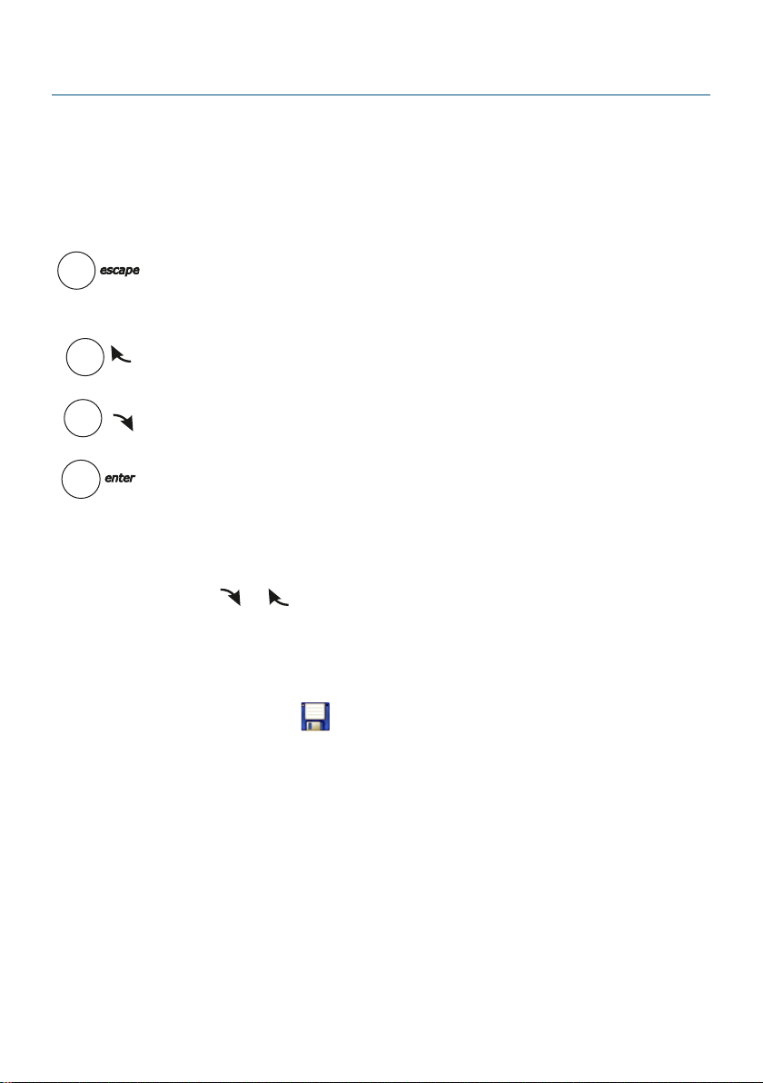
4 Menu navigation.........................................................................................7
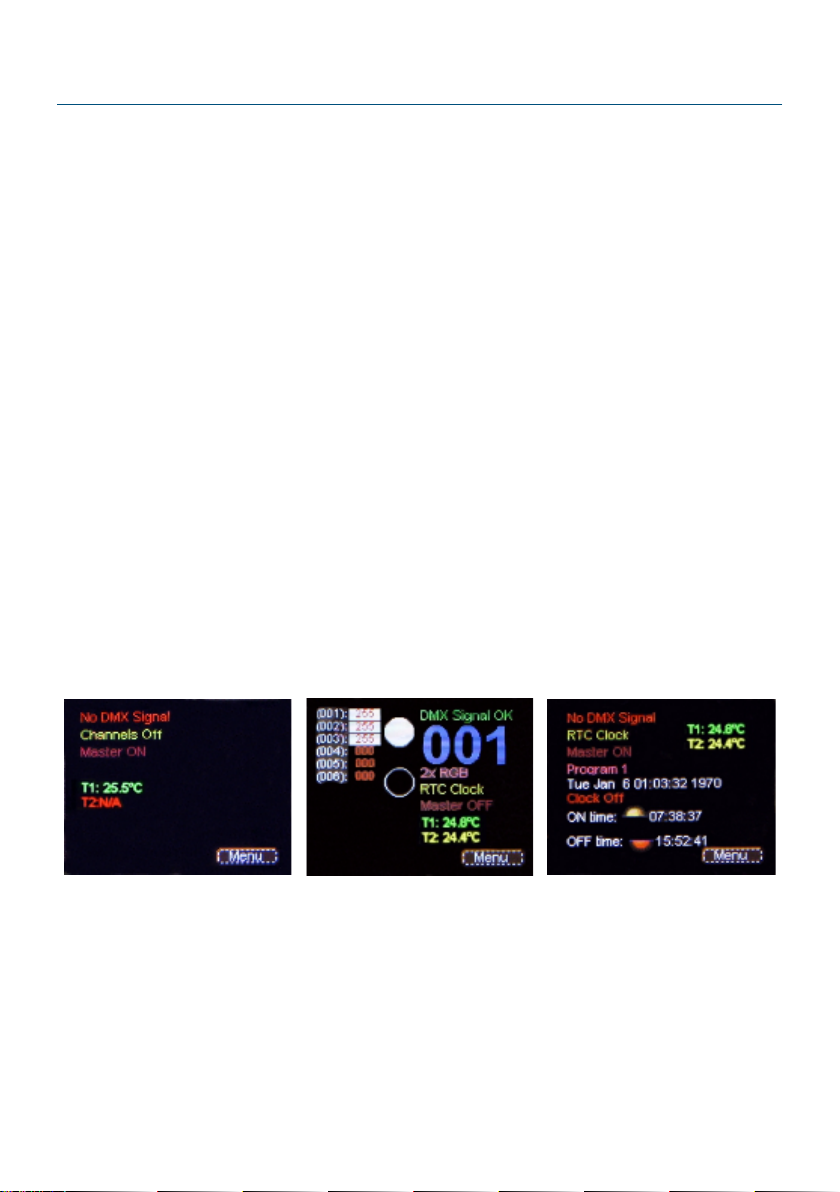
5 sing the device.........................................................................................8
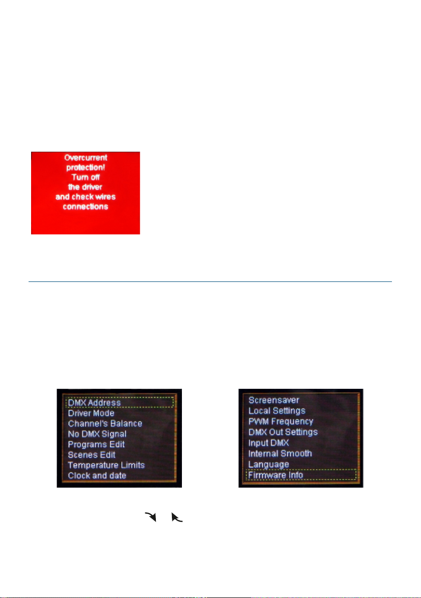
6 Programming device functions................................................................9
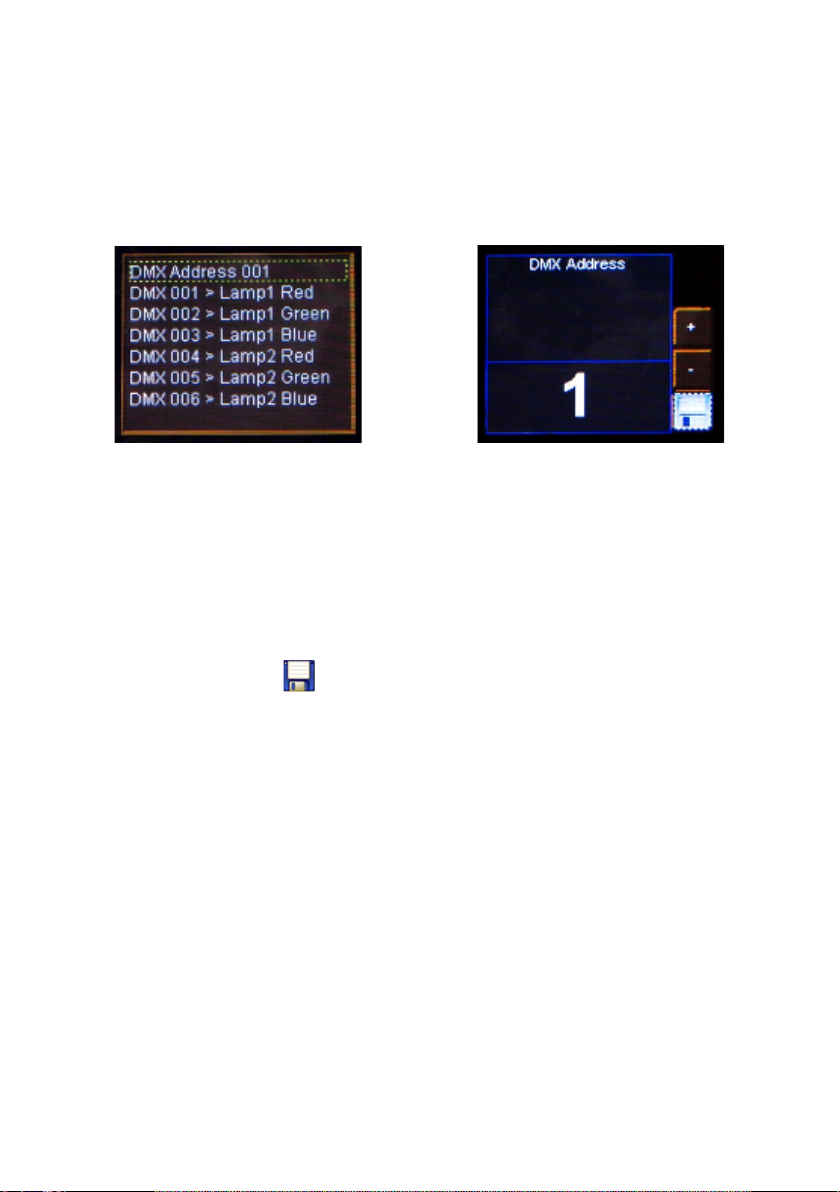
6.1 DMX address............................................................................................................. 10
6.2 Driver operation mode.............................................................................................10
6.3 Channel balance....................................................................................................... 13
6.4 No DMX signal response.........................................................................................14
6.5 Program editing........................................................................................................17
6.6 Scene editing............................................................................................................. 19
6.7 Temperature limits...................................................................................................19
6.8 Date and time............................................................................................................21
6.9 Screen saving............................................................................................................21
6.10 Local settings.......................................................................................................... 22
6.11 PWM frequency...................................................................................................... 23
6.12 DMX output.............................................................................................................23
6.12.1 Break Time......................................................................................................24
6.12.2 MAB Time....................................................................................................... 24
6.12.3 MBF Time........................................................................................................ 24
6.12.4 Packet gap...................................................................................................... 25
6.12.5 Channels number..........................................................................................25
6.13 DMX Out...................................................................................................................26
6.14 Smooth..................................................................................................................... 27
6.15 Language................................................................................................................. 27
6.16 Connection test...................................................................................................... 28
6.17 Firmware version....................................................................................................28
7 DMX signal connecting...........................................................................29
8 Connection scheme.................................................................................30
9 Dimensions...............................................................................................31
10 Technical data........................................................................................31

Manufacturer reserves the right to make modications in order to improve device
operation.
!"# #
$%&'()
*+*$%&'
,-."(/
0)*(*
12##
333##
4+
/
*

1 Description
5$$.$6555
$6$$657#556#75
#6$5".8"##$356653
#.$65#5$6""7
636"#659.4:,;$67".5
#6
<$#3"##7..36.8"
=$$>5$6"6"#6>#"
#6#5.5$$5".
#6
5656$#66
$#$7=56>5"5"7#.6$
#.,556"$765.$>35"65.
15#76 #$?"$765.#6$@$5
+"6#65656#7
5
5$5"+66 =3
365.A#35#6"7""$.
7=$$>5"+666 #3>$
"56"$>..#566$5#6
5$696;$."
9:365B;"67$5$7>#".
)

$5$"#"66$.6"$"
5$655#65.5.".8"679Cicker
freeD65.7;>3565 #6"7""##65
$"7=$$>BE,#"36"6355
6#"5##$353.#.$6
#5$35<$3F
2 Safety conditions
$6#3$35.G)HI53>
$".$"53.""67$1
5$67766$G)H356"+
67.6#676#35656$
56$"65"$#6$.656$
5$.
* =5$..76$"6>5"$#6$35
6$"65656$
) 6.67$355$$6$"6
( #$66"#".67
$356"#3"##7
55"$67#6$.66353$
58"$
"$$56 >#6"7$##.>5"$$$
(

5$66"$#6355"$76$.
/J
/ 5$66"#635#"350K
5.550)K
35$#$"7
3 Connectors and control elements
DMX input
DMX output
Temperature sensors
Control outputs
Power supply
12 - 48V DC
USB input
Display Control buttons

4 Menu navigation
".6$7#.. 765
$6$5.5$$5"31
G56"7#.$#35".
65."5.5#.5"935
6">5#.5escape" "5
Summary screen;
G65"5#5955L
";
G65"55.5955L
";
G3.6$$6#$6@
"
65.5".#>65C+DC-D"
567". 7$565.5"".5enter
7
5>5..#."#5#""
$5>6.5 7>6@7#.enter5
$66

5 Using the device
".5$6>53$35Menu##5
6=$656""$6$6.3 .
.5.6"$>.55.>$#".
$#"#.
=.5#"$6$>56$#75No DMX
Signal .B$5.5".$6#$
#$#7$356..>.ast value$
.$.5$96$6;
=5$66.>.DMX Signal OK.3
##,3>55.$$65566"#$
75.755>5$#$#$>
.2x RGB5#.$#665.$5Driver
operation mode"
Screen layout depending on enabled options and connected devices
6#55.$#7$5Menu 61
•Scene 1, Program 1, (…), ast valueG6"7"65"+
"5Menu →No DMX Signal

•Master ON/OFFG5$"="$
>Master ON$#7$I"$>Master OFF$#7$
•T1: N/A (23,4°C), T2: N/A (25,2°C)G#""$5
66$5NTC1 NTC2#"=
66$>53..##N/A
=5666766$5$
M>###.3##5
65$63 >35
"656$66.5
#3"##7$66.565
3.M6671OUT1, …, OUT6>5$6
6"$.
6 rogramming device functions
6@.Menu#".5enter">5"+"
##56#.75>6.5
6@56".5enter"5"3 "+
"6>355#6
#.#>6355735
#6"".5 7>$6@7"67#.
enter
/

6.1 DMX address
5DMX Address"+"$#76"7"5
$$65,7$">5$65"
53396.34:,#"8"65;
65.565">6$6@.#".
5enter ""3##3565"5
"6665.$66$6357"$$5>6
5C+DC-D 76$56$###$$
"6@.".5enter"65..5">7"
.7#.5 "56$6@57
#.enter
6.2 Driver operation mode
5Driver operation mode 3.5"65$
5##$".$#
,3#$5.5Driver operation mode"
6.5#5"$6@.7
#.enter

5$66#53.$ 1
•RGBG61$>.$"*66"65
•RGBWG61$>.>"$35)66"
65
•RGBWAG61$>.>">35$(66"
65
•RGBWAXG61$>.>">35>$$69;
66"65
•RGBDG61$>.$"*66"650
)65
•RGBWDG61$>.>"$35)66"
650(65
•RGBWADG61$>.>">35$(66"
65065
•RGBWAXDG61$>.>">35$(
66"65035$$6
65
•HSVGN"E"H"G935.5#3;>5@65
55">56$"$5535.5#3

•2x HSVG65HSV $
•2x RGBG65RGB $936.3#
5;
•2x RGBDG65RGBD$35)$
65
•6 ChannelsG765
•16bit 6 ChannelsG+665
•CW Dyn.G#356$$33596$M"
5@65;355$."656$65I
5$>5$66"#*#96#"
$M"6$3;
•WC Dyn.G#356$$33596$M"
5@65;355$."656$65I
5$>5$66"#*#96#"
$M"36$;
•CCW Dyn.G$#8"##$356$35$$$
335$$35"656$65
•WWC Dyn.G$#8"##$35335$$$
6$35$$35"656$65

6.3 Channel balance
5#3.5$""655
65#$75$=65..5".5
$.65$5"$.5.6
75#$#
5#>656 5Channel balance off$6@7
#.enter56 .553".$565
$""63$5"6>65Channel
balance on$6@7#.enter
*

5656".656@56$
657#.enter9565333##;>5#C+D
C-D56"6.###"
6@567#.enter
47".7
6. $6@7#.
enter
6.4 No DMX signal response
=5">#5$6O#.
35656.#5#765
666 =3".$5.566$6
355"$5"G.5"$"5"
#L$75"G5#5$65.9"$
$."$;$53.$$$6#
#
75#
5">
6$6@7
#.enter
)

#5"1
•Scene 1G69#.5Scene
editing ";5$$$6$5.
56>$"+#5enter"6.Scene 1 5
"G56"66##I"C+DC-D 7
6###6
47".7
6. $6@7#.
enter
•Program 1G5#.9#.
5Program editing";5$$$65
.65.5"5$#7$#.>35
"6535#6$.#
•Channels onG.$##6"#"
365$J
•Channels offG."#"6#7"$
•RTC ClockG5666 3.$$.
5#>#6@6#.6>$#$.55
"$5"5"655"66$.
356553"$5##.
(

5">65RTC Clock#$6@5636
355enter "565333##1
5@#"$5Astronomical Clock36.
35653365$66$.566 #+=
66$#.$6>.5".5,3>
5666 66"$66$.5$#"
5 ocal settings"$5$$$75
$
53565"735655
#$6$6$$$$
5.$$6 ."$6"$#".
.5.535655.6$
P7"$.5"H"65.$
6@.635enter
•ast DMX valueG6.5#>5.
$##>5$6"$"
•Master/Slave mode: Master (Slave)G5$>#
$3555$63 $56.
..5$$##556+6$

$5$3#7.
6.5 rogram editing
Program editing"35##.$6>
3565$$"#.6#$>6"75"5
#3.56"#6"#.35653"$
5$#5.$5"6
56"5@#.533$5
36.633$5#
5#$$6
6$$"#>65#6@$#35
$$".5 7>56@567#.
enter

.$$".$#7$5" 1
•Pr1 – Pr8G#."#G653
$"6.65.5.5#.
•Sc1 – Sc20G6"#>65
$5#$$
•AllG76.5#># 65.5
.#.6"35655"6
6$
•XF (xfade)G$G5$.
•ST (scene time)G5.5676$
•Cont/EndG6""#.6#76 5$
•Ch01:000 – Ch36:255G"8"65((
.$#"#5"#"65>6
535657"3 65.>5#5enter 75>
"5C+DC-D"3"$6@7#.enter

6.6 Scene editing
=5Scene editing">#65.#.
.65Program editing"+">6.56
$#7#7#."##>5""6
#".5$>5#.$6#7$
6""75.#6".$6$5(
.$.
6.7 Temperature limits
5#3.#""3565>65$>
#36"#"5$6#3$75$56
##$35656$355.5#"
53#"3565#"6
66$>6###"56>5
.5#3#"Sensor on$5.5#3
#"9#;Sensor off###
/

47"
.76.
$6@7#.
enter
65.5"5#".>
6###"56$6@7#.enter
36355#""@$3##65.
5#"35#55$$6$5#"
5"6>.(.$.
5 imit#3$.5.5#3
"6$#"#5#"
",7$">5$$5
"6>"656 5@$53$ imit567#.
5enter "5>$#6$.5#+#"55$>
#33$$5#3"$
Power
Temperature
0Sensor On
(by default 50 C)
°
Sensor Off
(by default: 80 C)
°
100%
Table of contents
Other PXM DC Drive manuals
Popular DC Drive manuals by other brands

Danfoss
Danfoss FC 302 instruction manual

Drivecon
Drivecon XT Series Service manual

Lenze
Lenze L-force EWZ Mounting instructions

Rockwell Automation
Rockwell Automation Allen-Bradley PowerFlex 750 Series Reference manual

Bosch
Bosch BDU3380 owner's manual

Danfoss
Danfoss VLT 5000 Series Installation Startup Check List

Unimotion
Unimotion MTV Series Use, Maintenance and Assembly Instructions

Siemens
Siemens SINAMICS S120 Commissioning manual

YASKAWA
YASKAWA HV600 Installation & Startup

Wittenstein
Wittenstein cyber dynamic system operating manual

SMC Sierra Monitor
SMC Sierra Monitor FieldServer FS-8700-125 Stulz manual

FALK
FALK Ultramite UB Installation & maintenance instructions