S&S Northern Merlin 3000S User manual

User Manual Merlin 3000S
Iss: 10 Page 1
Merlin 3000S
Demand Control Kitchen Ventilation System
INSTALLATION & OPERATION MANUAL
Please read these instructions carefully and retain for future use.
These instructions can be downloaded in electronic form on the product website (www.snsnorthern.com) or
a printed version can be ordered free of charge via S&S Northern Limited.

User Manual Merlin 3000S
Iss: 10 Page 2
Contents
Important Information ....................................................... 3
Installation .................................................................... 4
General Product Information....................................................................................4
System Positioning ..................................................................................................4
Electrical Connections ..............................................................................................5
Access & Navigate Settings ...................................................................................10
Settings Switch #1 Overview..................................................................................11
Settings Switch #2 Overview..................................................................................12
Duct Temperature vs 0-10V Fan Output ................................................................13
Operation .....................................................................15
Initial Power Up......................................................................................................15
Adjust the Screen Brightness.................................................................................15
Fan Boost Button....................................................................................................16
Warning Status Screens.........................................................................................16
Fault Status Screens ..............................................................................................17
Maintenance .................................................................18
Technical Specification.....................................................19

User Manual Merlin 3000S
Iss: 10 Page 3
Important Information
Warning Symbol
Where this symbol is used, consult the manual to understand any potential hazards and how to avoid them.
The information contained within this manual should be referenced for typical installation and operation only.
Isolate the equipment from all hazardous live power sources before opening the cover.
Any parts that form part of the connections/installation must have a minimum fire-retardant rating of UL 94 V-1.
For site specific requirements that may deviate from the information in this guide –contact your supplier.
If the equipment is used in a manner not specified, the safety provided by the equipment may be impaired.
This device is designed for indoor operation only.
Never ignore your device when in alarm.
This device requires a continual supply of electrical power –it will not work without power.
This device should not be used to substitute proper installation, use and/or maintenance of fuel burning appliances
including appropriate ventilation and exhaust systems.
The device is not intended for use in potentially explosive atmospheres.
Your product should reach you in perfect condition, if you suspect it is damaged, contact your supplier.
Warranty Statement
All products are engineered, designed and 100% quality tested in accordance with the latest internationally
recognised standards under a Quality Management System that is certified to ISO 9001. The manufacturer
warrants to the original consumer purchaser, that this product will be free of defects in material and
workmanship for a period of three (3) years from date of purchase. The manufacturer’s liability hereunder is
limited to replacement of the product with repaired product at the discretion of the manufacture. This
warranty is void if the product has been damaged by accident, unreasonable use, neglect, tampering or other
causes not arising from defects in material or workmanship. This warranty extends to the original consumer
purchaser of the product only.
Any implied warranties arising out of this sale, including but not limited to the implied warranties of
description, merchantability and intended operational purpose, are limited in duration to the above warranty
period. In no event shall the manufacturer be liable for loss of use of this product or for any indirect, special,
incidental, or consequential damages, or costs, or expenses incurred by the consumer or any other user of
this product, whether due to a breach of contract, negligence, strict liability in tort or otherwise. The
manufacturer shall have no liability for any personal injury, property damage or any special, incidental,
contingent, or consequential damage of any kind resulting from gas leakage, fire, or explosion. This warranty
does not affect your statutory rights.
During the above warranty period, your product will be replaced with a comparable product if the defective
product is returned together with proof of purchase date. The replacement product will be in warranty for the
remainder of the original warranty period or for six months –whichever is the greatest.
Information for consumers of electrical & electronic equipment.
When this product has reached the end of its life, treat as Waste Electrical & Electronics Equipment
(WEEE). Any WEEE marked products must not be mixed with general household waste, but kept
separate for the treatment, recovery and recycling of the materials used.
Please contact your supplier or local authority for details of recycling schemes in your area.

User Manual Merlin 3000S
Iss: 10 Page 4
Installation & Configuration
General Product Information
For optimum results and protection, all system sensing elements should be utilised together, but any
combination can be used.
The Merlin 3000S is an energy saving system designed specifically for commercial kitchens. The system acts
an interlock between the ventilation and the gas solenoid valve, while also varying the speed of the ventilation
via a 0-10vdc output.
The system has 2 built-in 0-10VDC outputs. This is designed to vary the speed of the ventilation system(s)
based on either, real-time gas usage via a turbine gas meter, Carbon Dioxide (CO2) levels in the area,
smoke/steam detection in the canopy using optical sensors or heat detection in the extract ductwork using a
thermostat. For the best and most accurate results, all should be used together but any combination of the 4
sensors can be used.
As the CO2 or gas usage increases in the commercial kitchen, the Merlin 3000S will increase the speed of the
ventilation system to provide the perfect cooking environment. Conversely, when only minimal gas is being
used and the CO2 levels are low, the Merlin 3000S will reduce the speed of the ventilation systems, saving
energy and money.
The optical sensor will increase the ventilation should it detect excess smoke or steam in the canopy along
with the duct mounted heat sensor to monitor excess heat in the duct.
The Merlin 3000S also carries out its duty as a traditional ventilation interlock and gas pressure proving
system alongside the ventilation on demand capabilities. This allows for one single small control panel in the
kitchen, freeing up valuable real estate on the kitchen walls.
System Positioning
Merlin 3000S
In accordance with any applicable regulations. Easy accessibility is
recommended for both status observation and alarm purposes.
Merlin CO2 Monitor
1-3m away from canopy.
>1m from any draft zones and 1.7m from ground level / Breathing zone.
Merlin CO Detector
1.7m from ground level / Breathing zone.
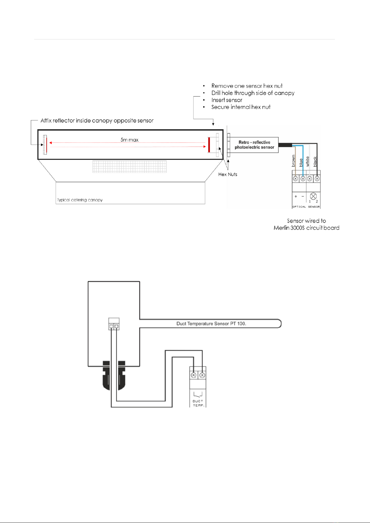
Optical Sensor
Fitted inside of canopy. 5m Max from infra-red reflector fitted opposite sensor.
Duct Temp Sensor
Fitted inside of ductwork where heat may pass through.
Speed Controller
Install away from Merlin 3000S panel to avoid electrical noise.
If in doubt, contact your supplier.

User Manual Merlin 3000S
Iss: 10 Page 5
Electrical Connections
1POWER IN
The Merlin 3000S requires an AC single phase power supply rating of 100-240V~ connected to [Power In]
terminal using a 3A fuse spur. Frequency 50-60Hz.
2GAS VALVE
100-240V AC Power Output to a gas solenoid valve. Refer to the gas valve for more information.
3CONTACTOR
100-240V AC Power Output to an Electrical Contactor. Maximum current of the valve and Contactor combined
should not be loaded over 3 Amps.
4FAN CURRENT SENSOR - Extract
These terminals are used to receive an input signal from external air pressure switches or external current
monitors. These terminals are linked out as a factory setting. Wiring to air pressure differential switches and
current monitors should be made using two-core volt free connections.
5FAN CURRENT SENSOR - Supply
These terminals are used to receive an input signal from external air pressure switches or external current
monitors. These terminals are linked out as a factory setting. Wiring to air pressure differential switches and
current monitors should be made using two-core volt free connections.
NOTE: Current Sensor Terminals not in use should be left with link screwed in. e.g., if only one fan is used.
User Manual Merlin 3000S
Iss: 10 Page 6
6BMS OUT
Terminals are available for Building Management Systems (BMS) to make or break a circuit (gas valve open
or valve closed). Terminations: Normally Closed / Common / Normally Open. These are volt free connections.
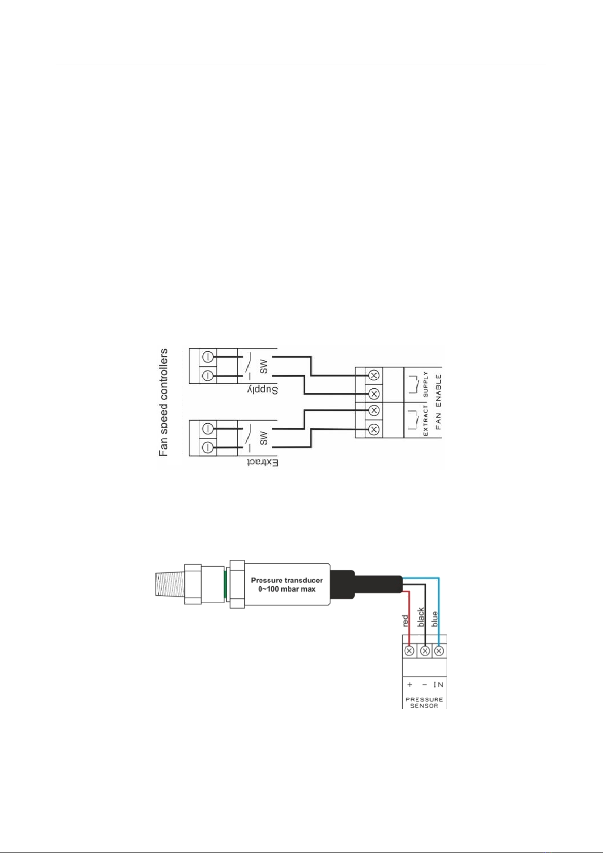
7FAN ENABLE - Extract
This terminal will switch when the key is turned on and off.
These terminals are linked to a fan switch (speed controllers supplied separately) which can provide power to
the fans when the panel is switched on. This can work as normally closed (N/C) or normally open (N/O).
8FAN ENABLE –Supply
This terminal will switch when the key is turned on and off.
These terminals are linked to a fan switch (speed controllers supplied separately) which can provide power to
the fans when the panel is switched on. This can work as normally closed (N/C) or normally open (N/O).
9PRESSURE SENSOR
Connect to the gas pressure transducer (supplied separately) to these terminals and connect to the
downstream port on the gas solenoid valve. Operating pressure: Min = 12mbar Max = 100mbar
10 EM REMOTE
This terminal is linked out as a factory setting and used for remote emergency shut off devices that are volt
free and wired using two-core cable.

User Manual Merlin 3000S
Iss: 10 Page 7
11 CO DETECTOR
12V DC Power [ + / - ] and [ ] can be wired to a Merlin Carbon Monoxide (CO) gas detector.
If no detector is being used leave the link in between the “ ”.
12 CO2 Zone 1 0-10V Input
A 0-10VDC signal from a Merlin CO2Monitor will automate the speed of extract and supply fans dependant on
CO2 detected levels detected.
13 CO2 Zone 2 0-10V Input
A 0-10VDC signal from a Merlin CO2Monitor will automate the speed of extract and supply fans dependant on
CO2 detected levels detected.
14 CO2 MONITOR
This is a linked-out terminal and can be connected to a Merlin Carbon Dioxide (CO2) monitor. If no CO2
Monitor is being used - leave the link in between the “ ” terminal.

User Manual Merlin 3000S
Iss: 10 Page 8
15 GAS METER
Before any connections are made, please refer to the Gas Meter operation manual. This is a low voltage
connection with a varied pulse input to drive fans on an automatic varied speed based on real-time gas
usage.
NOTE: TBX –Turbine Gas Meter has two types of pulse output –'unit pulse' and 'high density pulse'. The
Merlin 3000S requires a high-density pulse wire.
16 FIRE PANEL
The terminal for fire alarms is detailed on the circuit board as [FIRE PANEL]. These connections are linked out
as a factory setting. Fire alarms should be volt free using two-core cable- normally closed and open upon
activation.
17 12VDC OUT
This is a permanent 12V DC output (max loading 150mA/~2W) when there is power at the panel. This is
normally used to power a Merlin PM2+ Current Monitor (supplied separately).
User Manual Merlin 3000S
Iss: 10 Page 9
18 OPTICAL SENSOR (ZONE 1)
The terminals detailed on the circuit board as [OPTICAL SENSOR] - [ + / - ] [ 1 / 2 ] are wired to the optical
sensor (supplied separately).
19 DUCT TEMP (ZONE 1)
This is a low resistance connection to the duct temperature sensor to drive fans on an automatic varied
speed based on extraction duct temperature levels.
20 OPTICAL SENSOR (ZONE 2)
See OPTICAL SENSOR (ZONE 1)
21 DUCT TEMP (ZONE 2)
See DUCT TEMP (ZONE 1)
User Manual Merlin 3000S
Iss: 10 Page 10
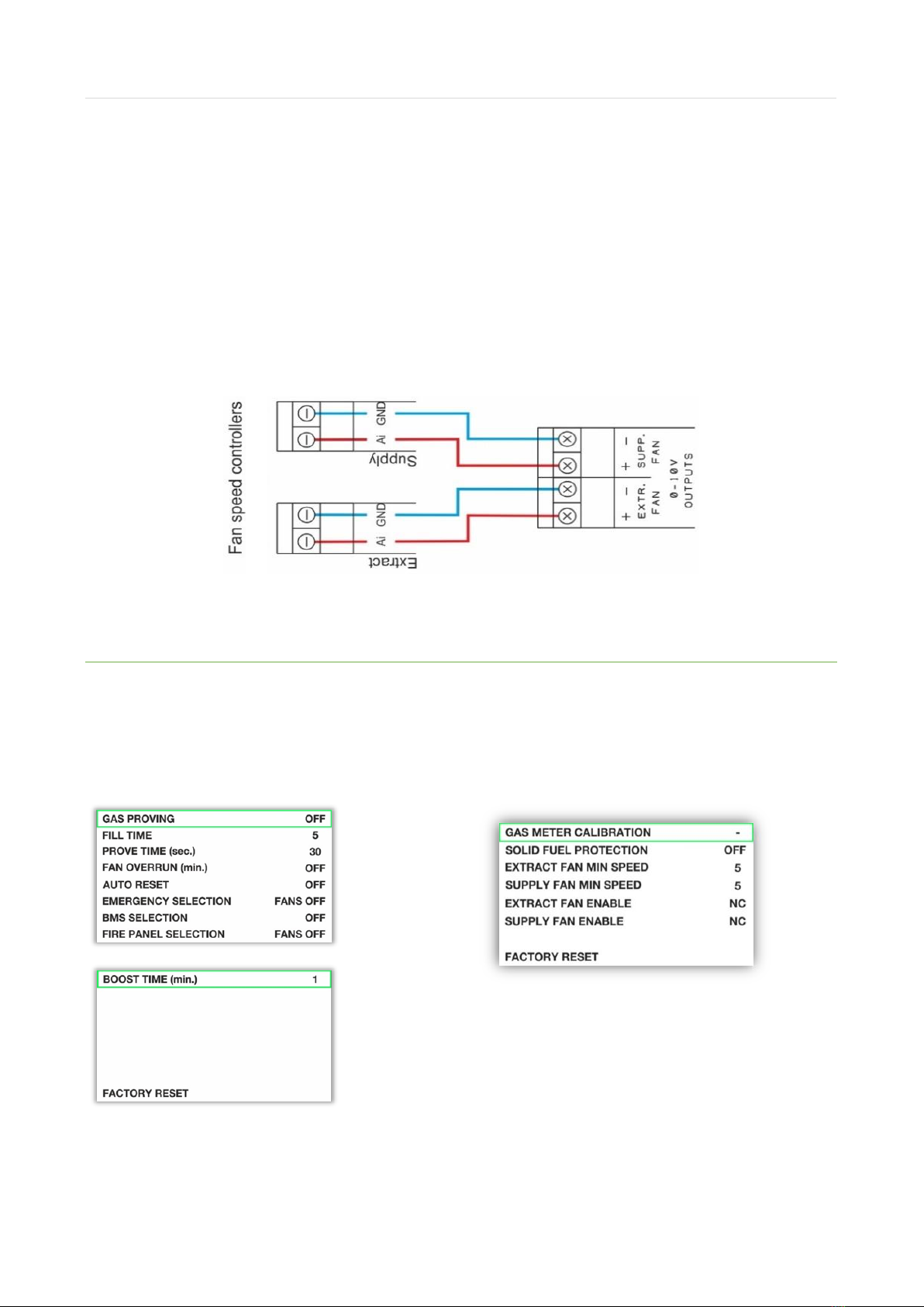
22 0 -10V OUTPUT –Extract Fan
The terminals for the 0-10VDC outputs are detailed on the circuit board as [EXTR. FAN] & [SUPP. FAN].
These connections are used to regulate external fan speed controllers (supplied separately) which can accept
this control signal.
23 0-10V OUTPUT –Supply Fan
The terminals for the 0-10VDC outputs are detailed on the circuit board as [EXTR. FAN] & [SUPP. FAN].
These connections are used to regulate external fan speed controllers (supplied separately) which can accept
this control signal.
Access & Navigate Settings
There are two internal ‘Settings’ Dipswitches (1 and 2).
Turn the key to the Off Position, turn one of the settings dip switches on (1 or 2) and then turn the key back
to the on position. A menu list will be displayed and will differ depending on which switch is turned on.
Menu Screen: Switch 1
Menu Screen: Switch 2
Navigate Menu
•Use ▲or ▼to select function (selection highlighted green).
•Press OK button (green frame will change to red).
•Use ▲or ▼to select appropriate value.
•Press OK button and wait until red frame returns to green.

User Manual Merlin 3000S
Iss: 10 Page 11
Settings Switch #1 Overview
Menu
Description
Default
GAS PROVING
This system proves by pressure testing that all gas taps and appliances are isolated
before the main gas valve will open. If you require gas pressure proving, enable by
selecting ON and adjust the initial FILL and PROVE times before the valve will open upon
start up.
OFF
FILL TIME
Gas Proving must be enabled. Fill the gas supply line for 5, 10, 15 or 20 seconds.
5s
PROVE TIME
Gas Proving must be enabled. Check the integrity of supply for 30, 45, 60, 75 or 90
seconds.
30s
FAN OVERRUN
An option for cooling the duct for a period when the 3000S is switched off by key. Fan
Overrun can be set from a period of 1 to 30 minutes. All input and outputs will be
switched off and only the fans will remain in operation.
OFF
AUTO RESET
In the event of a power loss the 3000S must be restarted manually by key switch. When
auto-reset is ON it will instruct the system to restart automatically when power is
restored.
OFF
EMERGENCY
SELECTION
The Merlin 3000S has a four (4) combination emergency selection feature:
•FANS OFF - Extract & Supply fan OFF (default).
•FANS ON - Extract & Supply fan ON at maximum speed.
•SUPP ON –Extract fan is OFF / Supply fan ON at maximum speed.
•EXTR ON –Supply fan is OFF / Extract fan ON at maximum speed.
Each option instructs the 3000S to shut down the gas supply and contactor when
Emergency Shutoff devices are activated.
OFF
BMS
SELECTION
This will tell the BMS whether the there is a gas supply. Factory set to OFF which signals
the BMS when the gas valve is open or closed.
When switched to ON, the 3000S will signal the BMS on any error fault, i.e., High CO2
or gas levels via detectors, Emergency shutoff activated, etc.
OFF
FIRE PANEL
SELECTION
The Merlin 3000S has a four (4) combination fire panel selection feature:
•FANS OFF - Extract & Supply fan OFF (default).
•FANS ON - Extract & Supply fan ON at maximum speed.
•SUPP ON –Extract fan is OFF / Supply fan ON at maximum speed.
•EXTR ON –Supply fan is OFF / Extract fan ON at maximum speed.
Each option instructs the 3000S to shut down gas supply and electrical contactor upon
activation by Fire Alarm via the fire panel.
OFF
FACTORY
RESET
All settings from the settings #1 menu can be restored to default.
N/A

User Manual Merlin 3000S
Iss: 10 Page 12
Settings Switch #2 Overview
Menu
Description
Default
GAS METER
CALIBRATION
Select [GAS METER CALIBRATION] option.
➢Fans start operating at max speed and the gas valve will open.
➢Turn all appliances on and set gas to maximum.
➢When all appliances are ready - press OK.
➢Calibration can take up to 3 minutes.
➢Whilst calibrating, the screen opposite will be displayed
The Merlin 3000S will then confirm successful calibration
If the system encounters a problem –the screen may display the following.
Too many pulses Not enough pulses
The 3000S will automatically increase the calibration time when it receives less than 12
pulses within 5 seconds and decreases calibration time when receiving more than 999
pulses within 5 seconds. Calibration is possible only when the 3000S receives 12 to 998
pulses within 2 to 60 seconds.
The system will measure three times the number of pulses and save an average value.
The calibration time will have an influence on the fan speed response time in relation to
CO2value and duct temperature
OFF

User Manual Merlin 3000S
Iss: 10 Page 13
SOLID FUEL
PROTECTION
The Merlin 3000S has a built-in solid fuel protection feature. When the 3000S is
switched OFF and solid fuel protection is set to ON it will instruct the system to continue
to check the Detector, CO2Monitor and Duct Temperature if applicable.
OFF
EXTRACT FAN
MINIMUM
SPEED
Setup the minimum speed for extract fan ranging from 1 –10 volts (displayed in bars).
5V
SUPPLY FAN
MINIMUM
SPEED
Setup minimum speed for supply fan in range from 1 –9 volts (displayed in bars).
WE DO NOT RECOMMEND A SUPPLY FAN SPEED HIGHER THAN EXTRACT FAN SPEED.
5V
EXTRACT FAN
ENABLE
The Merlin 3000S has a built-in fan speed control - ON/OFF feature. This can work as
N/O or N/C.
NC
SUPPLY FAN
ENABLE
The Merlin 3000S has a built fan speed control - ON/OFF feature. This can work as N/O
or N/C.
NC
FACTORY
RESET
All settings from the settings #2 menu can be restored to default.
N/A
Duct Temperature vs 0-10V Fan Output
Volt
Temp (C°)
Minimum Speed - 1V
From
Up to
Extract fan 0-10V out
(At minimum speed)
Supply fan 0-10V out
(At minimum speed)
0
<25
25
0
0.0
1
25.1
30
1.9
1.7
2
30.1
35
2.8
2.5
3
35.1
40
3.7
3.3
4
40.1
45
4.6
4.1
5
45.1
50
5.5
5.0
6
50.1
55
6.4
5.8
7
55.1
60
7.3
6.6
8
60.1
65
8.2
7.4
9
65.1
73
9.1
8.2
10
>73.1
10
9.0

User Manual Merlin 3000S
Iss: 10 Page 14
Volt
Temp (C°)
Minimum Speed - 5V
From
Up to
Extract fan 0-10V out
(At minimum speed)
Supply fan 0-10V out
(At minimum speed)
0
<25
25
0
0.0
1
25.1
30
5.5
5.0
2
30.1
35
6.0
5.4
3
35.1
40
6.5
5.9
4
40.1
45
7.0
6.3
5
45.1
50
7.5
6.8
6
50.1
55
8.0
7.2
7
55.1
60
8.5
7.7
8
60.1
65
9.0
8.1
9
65.1
73
9.5
8.6
10
>73.1
10.0
9.0

User Manual Merlin 3000S
Iss: 10 Page 15
Operation
Initial Power Up
To turn the unit ON - Turn the key switch to ON position. When the system is connected to the mains
electrical supply, the red dot of the S&S logo located on the bottom of the panel will illuminate. When no
power is present, this LED will not illuminate.
Upon powering up the 3000S, the system will display the following screen until the fan/s reach the speed set
by the engineer. After the fan/s have reached the desired settings, the system will continue as normal.
Under normal conditions –The display will show fan speed.
When 'Fan Overrun Time' is enabled the screen will display the period run time. To deactivate - press
emergency button or switch key ON.
Adjust the Screen Brightness
Hold the UP [▲] button on the front panel for ~3 seconds until the panel beeps. Press UP again to select
three brightness levels (High / Medium / Low).
Once you have selected your desired brightness, leave the panel for ~5 seconds and the brightness will set.

User Manual Merlin 3000S
Iss: 10 Page 16
Fan Boost Button
To boost the ventilation and prompt maximum fan speed - Press and Release the [Boost] button located on
front fascia and the pre-selected boost time will display on screen. When boost time reaches zero, the fans
will automatically return to normal operating mode.
To turn boost mode off - Press and Release the [Boost] button located on front fascia - the system will return
to normal operation.
Warning Status Screens
CO2HIGH Using 0-10V Input Terminals.
When CO2gas is detected above alarm level (see CO2Monitor
manual) the screen will display CO2 HIGH indication and the fans
output will be at maximum speed. When the CO2gas returns
below alarm level, the system will return to normal operation.
SMOKE / STEAM DETECTED
When smoke or steam is detected continuously for ~3 seconds, the warning screen will appear, and the fans
will operate at maximum speed. When smoke or steam is not detected continuously for ~5 seconds the
system will automatically return to normal.
When smoke or steam is detected for longer than 30minutes, the panel will buzz intermittently, and the
warning screen will appear to prompt a cleaning of the optical sensors.

User Manual Merlin 3000S
Iss: 10 Page 17
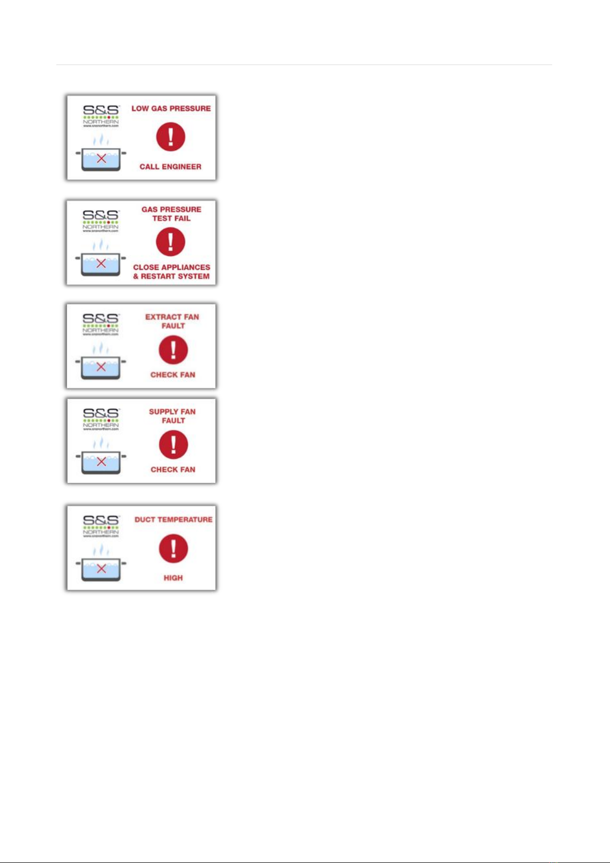
DUCT TEMPERATURE HIGH
When the temperature in the extraction duct reaches or rises
above 30°C, the fans will be driven at a speed dependant on the
temperature. When the temperature in the extraction duct
reaches or rises above 73°C, the warning screen will appear
and the fans will be driven at maximum speed.
When the temperature in the extraction duct drops below 73°C,
the warning screen will disappear, and the fans will continue at
a speed dependant on the temperature.
When the temperature drops below 30°C, system will automatically return to normal.
Fault Status Screens
EMERGENCY STOP If an emergency stop button (remotely or direct) is
pressed, the gas and contactor will shut off. Fans can be driven in a
combination upon emergency stop activation–see settings. The
Emergency Stop must be reset before restarting the system.
CARBON MONOXIDE DETECTED If the connected CO Detector detects
high concentrations of CO gas, the gas and contactor will shut off and
fans will run at maximum speed.
CO2HIGH When CO2gases rise above alarm level (see CO2Monitor
manual) the fault screen will appear. The gas and contactor will shut
off and fans will run at maximum speed.
FIRE ALARM ACTIVATED If the connected fire panel detects a fire the
gas and contactor will shut off. Fans can be driven in 4 combinations
–see settings.
User Manual Merlin 3000S
Iss: 10 Page 18
LOW GAS PRESSURE When gas supply pressure drops below 12mBar
for 10 seconds the fault screen will appear and the gas valve,
contactor and the fans will all shut off.
GAS PRESSURE TEST FAIL If the gas pressure test drops by more
than 10% below 12mBar the test will fail.
SUPPLY & EXTRACT FAN FAULT If a supply or extract fan fault is
detected for longer than 20 seconds - the gas, contactor and fans will
all shut off.
SOLID FUEL FEATURE PROTECTION The Merlin 3000S has a built-in
solid fuel protection feature. When the system is switched off and the
solid fuel protection is set to ON it will continue to instruct the system
to check the CO Detector, CO2Monitor & Duct Temperature if
applicable.
When all the above faults are rectified and safe, the system will automatically shut down again.
Maintenance
Keep your panel in good working order - follow these basic principles.
•Remove any dust/debris from the outer enclosure regularly using a slightly damp cloth.
•Never use detergents or solvents to clean your device.
•Never spray air fresheners, hair spray, paint, or other aerosols near the device.
•Never paint the device.

User Manual Merlin 3000S
Iss: 10 Page 19
Technical Specification
General
Model:
Merlin 3000S
Size: (H x W x D)
7.08 x 10.03 x 3” (180 x 255 x 77 mm)
Housing Material:
ABS Polylac - PA765 (Flame Rating UL94 V-1)
Mounting:
Indoor use - Wall Mounting
Weight:
1.7kg (3.74lb)
User Interface
Display:
4.3” TFT Touch Screen
Screen Brightness:
Adjustable 0-100%
Audible Alarm:
>60dB @ 3.28ft (1m). Quiet conditions.
Language:
English
Power Supply
Power Consumption:
6.9W max.
AC Power Rating:
100-240V~ 50/60Hz
Maximum Current:
28mA
Extract/Supply Fan Output
0.5A Max
Internal Fuse:
T3.15A L250V
Equipment
Overvoltage Category:
II
Pollution Degree:
2
Equipment Class:
2
Environmental
Operating:
-10 ~ 50°C / 14 ~ 122°F 30 ~ 80% RH (non-condensing)
Storage:
-25 ~ 50°C / -13~122F° up to 95% RH (non-condensing)
Altitude Rating:
2000m
Wiring
Typical
100-240V AC Rated terminals #18-12AWG-Tinned Copper
Other: #18-14AWG-Tinned Copper.
For field connections use wires suitable for at least 75°C (167°F)
Approvals
Electromagnetic Compatibility and
Electrical Safety
EN 61326-1:2013
IEC BS EN 61010-1

User Manual Merlin 3000S
Iss: 10 Page 20
Installation Details
Please pass this manual to the system owner / user.
Date of Installation:
Installation Location:
Organisation:
Stamp/Signature of the installer:
Every effort is made to ensure the accuracy of this document; however, S&S Northern can assume no responsibility for any errors or
omissions in this document or their consequences. S&S would greatly appreciate being informed of any errors or omissions that may
be found in the content of this document. For information not covered in this document, or if there is a requirement to send
comments/corrections, please contact S&S using the contact details.
S&S Northern Head Office
Tel: +44(0) 1257 470 983
Fax: +44(0) 1257 471 937
www.snsnorthern.com
Southeast Division
Tel: +44(0) 1702 291 725
Fax: +44(0) 1702 299 148
S&S Northern is the owner of this document and reserves all rights of modification without prior notice.
Other manuals for Merlin 3000S
1
Table of contents
Other S&S Northern Fan manuals


Popular Fan manuals by other brands

V-TAC
V-TAC VT-4012-3 instruction manual

Bastilipo
Bastilipo Mistral instruction manual

Modern Forms
Modern Forms Lucid installation instructions

ENERVEX
ENERVEX RSV Installation & operating manual

Vent-Axia
Vent-Axia ResponseSELV TP Installation and wiring instructions

Fantech
Fantech ERV-WI 500 Installation, operation and maintenance manual


