BYK LCM III User manual

Additives & Instruments
A member of
LCM III
Measure what you see.
Manual
Betriebsanleitung
Mode d’emploi
Istruzioni d´uso

1
Table of contents
Section 1 Specifications ........................................................................................................................................ 3
Section 2 General Information .............................................................................................................................. 5
2.1 Safety information .............................................................................................................................................. 5
2.1.1 Use of hazard information ......................................................................................................................... 5
2.1.2 Precautionary labels ................................................................................................................................. 5
2.1.3 Chemical and Biological Safety ................................................................................................................ 5
2.2 Overview of product ........................................................................................................................................... 6
Section 3 Installation ............................................................................................................................................. 7
3.1 Unpack the instrument ....................................................................................................................................... 7
3.2 Environment considerations ............................................................................................................................... 7
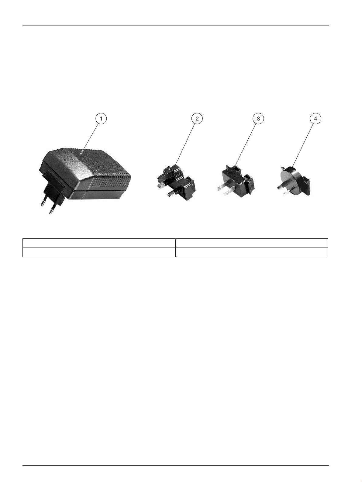
3.3 Power connections ............................................................................................................................................. 8
3.4 Connection ......................................................................................................................................................... 9
3.5 Cell compartments and cell adapter ................................................................................................................ 10
3.5.1 Cell compartments and adapter .............................................................................................................. 10
3.5.2 Installation of the cell adapter ................................................................................................................. 11
Section 4 Start Up ................................................................................................................................................ 13
4.1 Power the instrument on and off ...................................................................................................................... 13
4.2 Language selection .......................................................................................................................................... 13
4.3 Self-Check ....................................................................................................................................................... 13
4.4 Characteristics in continuous operation ........................................................................................................... 14
Section 5 Standard Operations ........................................................................................................................... 15
5.1 Overview .......................................................................................................................................................... 15
5.1.1 Tips for the use of the touch screen ........................................................................................................ 15
5.1.2 Use of the alphanumeric keypad ............................................................................................................ 15
5.1.3 Main Menu .............................................................................................................................................. 16
5.2 Instrument Setup mode .................................................................................................................................... 16
5.2.1 Operator ID ............................................................................................................................................. 16
5.2.2 Sample ID ............................................................................................................................................... 17
5.2.3 Date and time .......................................................................................................................................... 18
5.2.4 Display and sound preferences .............................................................................................................. 19
5.2.5 Power Management ................................................................................................................................ 19
5.2.6 PC and printer ......................................................................................................................................... 20
5.2.6.1 Printer setup ............................................................................................................................... 21
5.2.6.2 PC setup ..................................................................................................................................... 23
5.2.6.3 Print data .................................................................................................................................... 23
5.2.7 Password ................................................................................................................................................ 24
5.2.7.1 Deactivate a password ............................................................................................................... 25
5.3 Store, recall, send and delete data .................................................................................................................. 26
5.3.1 Auto/manual data storage ....................................................................................................................... 26
5.3.2 Recall stored data from the data log ....................................................................................................... 26
5.3.3 Send data from the data log .................................................................................................................... 27
5.3.4 Delete stored data from the data log ....................................................................................................... 28
5.4 Sampling and sample preparation ................................................................................................................... 29

2
Table of Contents
5.5 Color measurement ......................................................................................................................................... 30
5.5.1 Take a color measurement ..................................................................................................................... 31
5.5.1.1 Touch-sensitive areas on the measurement window .................................................................. 32
5.5.1.2 Parameter setup options ............................................................................................................. 33
5.5.1.3 Change the color scale after a measurement .............................................................................33
5.5.2 Determine the Iodine color value ............................................................................................................ 34
5.5.3 Determine the Hazen color value (Pt-Co or APHA-method) ...................................................................34
5.5.4 Determine the Gardner color value ......................................................................................................... 35
5.5.5 Mineral oil color value (ASTM D 1500 and ISO 2049) ............................................................................ 35
5.5.6 Determine the Saybolt color number (ASTM D 156) .............................................................................. 35
Section 6 Advanced Operations ......................................................................................................................... 37
6.1 System checks ................................................................................................................................................. 37
6.1.1 Instrument information ............................................................................................................................ 37
6.1.2 Upgrade of the instrument software ........................................................................................................ 38
6.1.3 Optical checks ......................................................................................................................................... 38
6.1.3.1 Verification kit ............................................................................................................................. 38
6.1.4 Output checks ......................................................................................................................................... 40
6.1.5 Lamp history ........................................................................................................................................... 40
6.1.6 Factory service ........................................................................................................................................ 41
6.1.7 Service time ............................................................................................................................................ 41
6.1.8 Instrument backup .................................................................................................................................. 43
Section 7 Maintenance ........................................................................................................................................ 47
7.1 Cleaning requirements ..................................................................................................................................... 47
7.1.1 Housing and cell compartment ............................................................................................................... 47
7.1.2 Display .................................................................................................................................................... 47
7.1.3 Cuvettes/sample cells ............................................................................................................................. 47
7.2 Insert or change of the battery ......................................................................................................................... 48
7.2.1 Information about using the battery ........................................................................................................ 49
7.2.1.1 Recycle the lithium battery .......................................................................................................... 49
7.2.1.2 Optimal operation of the battery ................................................................................................. 50
7.2.1.3 Lifespan of the battery ................................................................................................................ 50
7.2.1.4 Load the battery/Operating time ................................................................................................. 50
7.3 Lamp replacement ........................................................................................................................................... 51
Section 8 Troubleshooting .................................................................................................................................. 55
Index ...................................................................................................................................................................... 57

3
Section 1 Specifications
Specifications are subject to change without notice.
Performance specifications
Operating mode Color measurement
Colorimetric evaluation
DIN 6162 Iodine color value
ISO 6271 Hazen color value
ISO 4630 Gardner color value
ASTM D 1209 Saybolt color value
ASTM D 1500 Mineral oil color value
Source lamp Gas-filled Tungsten (visible)
Wavelength range 400–700 nm
Wavelength accuracy ± 2 nm
Wavelength calibration Automatic
Wavelength range for color
measurement 400 to 700 nm
Photometric accuracy 5 mAbs at 0.0 to 0.5 Abs
1% at 0.50 to 2.0 Abs
Photometric linearity < 0.5 % to 2 Abs
< = 1 % at > 2 Abs with neutral glass at 546 nm
Stray light > 3.0 Abs. at 500 nm with OG570/3
Data log 200 color measurements
Physical and environmental specifications
Width 220 mm (8.6 in.)
Height 135 mm (5.3 in.)
Depth 330 mm (12.9 in.)
Weight 4.06 kg (8.95 Ibs) without battery
4.38 kg (9.66 Ibs) with battery
Operating requirements 10–40 °C (50–104 °F), max. 80 % relative humidity (non-condensing)
Storage requirements –40–60 °C (-40–140 °F) max. 80 % relative humidity (non-condensing)
Additional technical data
Mains connection 15 V- / 30 VA
Plug-in power supply unit: (100–240 V/50–60 Hz)
Interfaces Use only screened cables with maximum length of 3 meters.
1 x USB type A
1 x USB type B
Enclosure rating IP 41 with closed lid
IP 42 with Protective Cover in place
Protection Class Safety class II

4
Specifications

5
Section 2 General Information
2.1 Safety information
Please read this entire manual before unpacking, setting up or
operating this equipment. Pay attention to all danger, warning and
caution statements. Failure to do so could result in serious injury to
the operator or damage to the equipment.
To make sure that the protection provided by this equipment is not
impaired, do not use or install this equipment in any manner other
than that specified in this manual.
2.1.1 Use of hazard information
DANGER
Indicates a potentially or imminently hazardous situation
which, if not avoided, will result in death or serious injury.
WARNING
Indicates a potentially or imminently hazardous situation
which, if not avoided, could result in death or serious injury.
CAUTION
Indicates a potentially hazardous situation that may result in
minor or moderate injury.
Important Note: Indicates a situation which, if not avoided, may
cause damage to the instrument. Information that requires special
emphasis.
Note: Information that supplements points in the main text.
2.1.2 Precautionary labels
Read all labels and tags attached to the instrument. Personal injury
or damage to the instrument could occur if not observed. A symbol,
if noted on the instrument, will be included with a danger or caution
statement in the manual.
2.1.3 Chemical and Biological Safety
DANGER
Potential Chemical/ Biological Exposure Hazards. Handling
chemical samples, standards and reagents can be dangerous.
Users of this product are advised to familiarize themselves
with safety procedures and the correct use of chemicals, and
to carefully read all relevant Material Safety Data Sheets.
This symbol, if noted on the instrument, references the instruction manual for operation and/or safety information.
Electrical equipment marked with this symbol may not be disposed of in European public disposal systems after
12 August of 2005. In conformity with European local and national regulations (EU Directive 2002/96/EC),
European electrical equipment users must now return old or end-of life equipment to the Producer for disposal at no
charge to the user.
Note: For return for recycling, please contact the equipment producer or supplier for instructions on how to return
end-of-life equipment, producer-supplied electrical accessories and all auxiliary items for proper disposal.

6
General Information
Normal operation of this instrument may involve the use of
hazardous chemicals or biologically harmful samples.
• The user must observe all cautionary information printed on the
original solution containers and safety data sheet prior to their use.
• All waste solutions must be disposed in accordance with local and
national law.
• The type of protective equipment must be selected according to
the concentration and amount of the dangerous substance at the
specific workplace.
2.2 Overview of product
The LCM III is a color measuring instrument for determin the color
values of transparent, optically clear liquids. The instrument comes
with a complete set of application programs and multi-language
support.
The LCM III can carry out an exact colorimetric evaluation in
conformity with ISO/ASTM standards with just a single
measurement and display the result in terms of traditional color
systems such as Iodine, Hazen or Gardner color numbers.

7
Section 3 Installation
WARNING
Electrical and Fire Hazards. Use only the provided power
supply. Only qualified personnel should conduct the tasks
described in this section of the manual.
3.1 Unpack the instrument
The LCM III comes packaged with the following items:
•LCM III
•Dust cover
•External power supply, including 4 adapter for EU, UK, USA
and AUS/China
•cuvette/cell adapter Z
•LCM III user manual
Note: If any of these items are missing or damaged, contact the
manufacturer or a sales representative immediatly.
3.2 Environment considerations
The following conditions are necessary to make sure correct
instrument operation and accurate results:
•Place the instrument firmly on an even surface. Do not push
any objects under the instrument.
•Maintain an ambient temperature of 10 to 40 ºC (50 to 104 ºF)
for proper instrument operation.
•The relative humidity should be less than 80 %; moisture
should not condense on the instrument.
•Leave at least a 15 cm (6 in.) clearance at the top and on all
sides for air circulation to avoid overheating of electrical parts.
•Do not operate or store the instrument in extremely dusty,
damp or wet locations.
•Keep the surface of the instrument, the cell compartment and
all accessories clean and dry at all times. Splashes or spills on
and in the instrument should be cleaned up immediately (see
section 7.1 on page 47).
•After a continuous operating time of more than 24 hour without
switching off the instrument we recommend to perform a new
calibration with a distilled water cuvette/sample cell.
•After a continuous operating time of more than 7 days without
switching off the instrument we recommend to switch off and on
the instrument to perform a new system check with filter
adjustment and lambda-calibration.
Important Note: Protect the instrument from temperature
extremes, including heaters, direct sunlight and other heat sources.

8
Installation
3.3 Power connections
Install the correct adapter plug on the supplied external power
supply (Figure 1). Slide the adapter on until it "clicks" into position.
Correctly mounted, both housing of power supply and plug are in
line. Plug the external power supply cord into the connector on the
back panel of the instrument, then plug the supply into a power
outlet (100–240 V~ / 50–60 Hz). Press the power switch on the
back of the instrument to initialize power (Figure 2 on page 9).
Figure 1 Power adapter
1Power supply with EU adapter plug installed 3USA adapter plug
2UK adapter plug 4AUS/China adapter plug

9
Installation
3.4 Connection
The LCM III has two USB interfaces as a standard feature, located
on the back of the instrument (Figure 2).
The USB Type A interface is used for communications with a
printer, USB memory stick or keyboard. A USB memory stick is
used to update instrument software.
The USB Type B interface is used for communications with a PC.
The optional Data Trans software must be installed on the PC for
this use.
A USB hub may be used to connect several accessories at a time.
Note: USB cables must not be longer than 3 meters (10 feet).
These USB interfaces enable data and graphics to be output to a
Printer and a PC and upgrade instrument software (see
section 6.1.2 on page 38).
Figure 2 Interfaces
1On/Off switch 4Cover
2USB type B 5USB type A
3Plug in power supply

10
Installation
3.5 Cell compartments and cell adapter
3.5.1 Cell compartments and adapter
The LCM III has two cell compartments (Figure 3). Only one
cuvette/sample cell type at a time can be used for a measurement.
Cell compartment #1
•11-mm round cuvettes/sample cells
For measurements with 11 mm round cuvettes/sample cells in
cell compartment #1 insert the adapter Z into cell
compartment #2.
Cell compartment #2
Cell compartment #2 uses adapters to accommodate different
cuvette/sample cell types.
•50 mm rectangular cuvettes/sample cells (can be inserted
directly into the cell compartment without using an adapter).
•10 mm square cuvettes/sample cells (can be inserted with the
adapter Z)
Important Note: Be sure that the adapter Z is inserted proper into
the cell compartment. Press the adapter down until it snap into the
compartment.
Figure 3 Cell compartments
1Cell compartment #1 2Cell compartment #2

11
Installation
3.5.2 Installation of the cell adapter
1. Open the cell compartment.
2. Insert the adapter for measurements with the round
cuvette/sample cell (11 mm) and/or 10 mm square
cuvette/sample cell so the arrow on top of the adapter points to
the left (Figure 4) and the orientation tab fits the groove in the
compartment opening.
Note: The arrow on top of the adapter indicates the direction of the light
beam path.
Figure 4 Cell adapter Z
1Adapter Z: 10 mm square cell adapter

12
Installation

13
Section 4 Start Up
4.1 Power the instrument on and off
1. Plug in to the power supply (laboratory analysis) or insert the
battery (field analysis).
2. The push-button switch on the back of the instrument switches
the instrument on (press for about 1 second) and off (press for
about 3 to 5 seconds). An acoustic signal confirms that the
instrument has been switched off.
Note: Do not turn the instrument off and on in rapid succession. Always
wait about 20 seconds before turning the instrument on again, otherwise
the electronic and mechanical systems will be damaged.
4.2 Language selection
The LCM III software includes several language options. The first
time the instrument is turned on, the language selection screen will
appear.
1. Select the desired language.
2. Press OK to confirm. The self-check will start automatically.
Changing the language setting
The instrument functions in the selected language until the option is
changed.
1. While turning the instrument on, touch the screen at any point
until the list for selecting a language appears (about
30 seconds).
2. Select the required language.
3. Press OK to confirm. The self-check will start automatically.
4.3 Self-Check
Each time the instrument is powered, a series of diagnostic tests
are performed automatically to make sure operation of major
system components.
This procedure, which takes approximately two minutes, checks the
system, lamp, filter adjustment, wavelength calibration and voltage.
Each test which functions correctly is confirmed with a check mark.
Note: For further error messages during self-check, see Section 8 on page
55.

14
Start Up
The Color Measurement Menu is displayed when diagnostics are
completed. Insert a cuvette/sample cell with distilled water to
calibrate.The calibration starts automatically when the LCM III
recognizes a 11 mm round vial in the cell compartment #1. For the
use of square cuvettes/sample cells in the cell compartment #2,
press Start to start the calibration.
Insert the sample cuvette/cell. For the use of 11 mm round vials the
measurement starts automatically. For the use of square
cuvettes/sample cells in the cell compartment #2, press Measure to
start the measurement.
See section 5.1.3 Main Menu on page 16 for a detailed description.
4.4 Characteristics in continuous operation
After a continuous operating time of more than 24 hour without
switching off the instrument we recommend to perform a new
calibration with a distilled water cuvette/sample cell.
After a continuous operating time of more than 7 days without
switching off the instrument we recommend to switch off and on the
instrument to perform a new system check with filter adjustment
and lambda-calibration.

15
Section 5 Standard Operations
5.1 Overview
5.1.1 Tips for the use of the touch screen
The entire screen is touch-activated. To make a selection, press the
screen with a fingernail, fingertip, pencil eraser or a stylus. Do not
press the screen with a sharp object, such as the tip of a ball
point pen.
•Do not place anything on top of the screen, to prevent damage
or scratching on the screen.
•Press keys, words or icons to select them.
•Use scroll bars to move up and down long lists very quickly.
Press and hold the scroll bar, then move up or down to move
through the list.
•Highlight an item from a list by pressing it once. When the item
has been successfully selected, it will be displayed as reversed
text (light text on a dark background).
5.1.2 Use of the alphanumeric keypad
This display is used to enter letters, numbers and symbols as
needed when programming the instrument. Unavailable options are
disabled (grayed out). The icons on the right and left of the screen
are described in Table 1.
The central keypad changes to reflect the selected entry mode.
Press a key repeatedly until the desired character appears on the
screen. A space can be entered by using the underscore on the
YZ_ key.
Note: A USB keyboard (with US keyboard layout) or a USB Barcode
handset scanner can be used for input.
Table 1 Alphanumeric keypad
Icon / key Description Function
ABC/abc Alphabetic When entering alphabetic characters (ex. user-entered units), this key allows to
toggle between upper and lower case letters.
# % Symbols Punctuation, symbols and numerical sub- and superscripts may be entered.
123 Numeric For entering regular numbers.
CE Clear Entry Clear the entry.
Left Arrow Backspace Moves back one position. This deletes the character previously entered in the new
position.
Right Arrow Advance Moves to the next space in an entry when two adjacent characters occur on the
same key.

16
Standard Operations
5.1.3 Main Menu
A variety of modes may be selected from the Main Menu. Table 2
briefly describes each menu option.
5.2 Instrument Setup mode
1. Select Instrument Setup in the Main Menu.
A selection of configuration options appear.
5.2.1 Operator ID
Use this option to enter up to 30 sets of operator initials (up to five
characters each). Also the color can assigned for each Operator ID.
This feature helps record which operator measured each sample.
Table 2 Main Menu options
Option Function
Color Measurement The COLOR MEASUREMENT mode is used to determine visual color values like Hazen,
Gardner and Saybolt
System Checks The system checks menu offers a number of options, including optical checks, output checks,
lamp history, instrument update, service time and instrument backup.
Recall Data Stored data can be recalled, filtered, sent to Printer, Memory stick or PC and deleted.
Instrument Setup In this mode, user-specific or method-specific settings can be entered: Operator-ID, Sample-ID,
Date & Time, Display & Sound, PC & Printer, Password

17
Standard Operations
1. Press Operator ID in the Instrument Setup.
2. Press New to enter a new Operator ID.
3. Use the alphanumeric keypad to enter a new Operator ID.
4. Press OK to confirm.
5. The display shows the selected Operator ID.
6. Press OK to return to Instrument Setup.
7. The selected Operator ID is activated.
Note: Press Delete to remove an Operator ID from the list.
Note: Alternatively, enter or change an Operator ID in measurement mode.
In the results screen, press Options>More>Instrument Setup or if an
Operator ID is already assigned, select the Operator ID symbol
immediately in the results screen.
5.2.2 Sample ID
Use this option to enter up to 100 Sample Identification tags (up to
13 characters each) into the instrument. Sample IDs can be used to
specify the sample location or other sample specific information.
1. Press Sample ID in the Instrument Setup.
2. Press New to enter a new Sample ID.

18
Standard Operations
3. Use the alphanumeric keypad to enter a new Sample ID.
Note: If a USB Barcode handset scanner is connected, Sample IDs
can also be scanned.
4. Press OK to confirm.
5. To number the Sample IDs sequentially (e.g. Inflow (01 etc.)),
select Add Number.
•Use the arrow keys to specify the first number of the
sequence.
•Use the key between the arrow keys to enter the first
number of the sequence using the alphanumeric keypad.
6. Press OK to return to Instrument Setup.
7. The Sample ID is activated. Each Sample ID is automatically
numbered in ascending order after a measurement. The
number is shown in parentheses behind the Sample ID.
Note: To remove a Sample ID, highlight the ID and press Delete.
Note: A Sample ID can be entered or changed in measurement mode. In
the results screen, press Options>More>Instrument Setup. If a Sample
ID is already assigned, select the Sample ID symbol in the results screen.
5.2.3 Date and time
1. Press Date & Time in the Instrument Setup.
2. The date and time are subdivided over a number of fields.
Press the appropriate field and use the arrow keys to change
the value.
3. Press OK to return to Instrument Setup.

19
Standard Operations
5.2.4 Display and sound preferences
1. Press Display & Sound in the Instrument Setup.
The following options will be displayed:
• Display Contrast—Adjusts the display brightness to suit
lighting conditions.
• Screen touch—Activates//Deactivates a short beep each time
the screen is pressed (Default:off).
• Reading done—Activates/Deactivates a sound when a
reading is complete (Default: short beep every time a reading is
complete).
•Timer—Adjusts the length of the timer sound. Select Short or
Long. Long beeps are recommended for noisy environments.
2. Select Long to change the number of audio signals.
Use the alphanumeric keypad to enter/specify the number of
audio signals (4–25).
Note: A high number of audio signals increases the duration of the
tones and a small number of audio signals reduces the duration of the
tones.
3. Press OK to confirm. The selected number of the audio signals
sounds as a corresponding acoustic signal.
4. Press OK to return to Instrument Setup.
5.2.5 Power Management
The LCM III can run on mains or battery power.
Note: The battery is not part of the standard scope of delivery.
1. Select Power Management in the ”Instrument Setup“ menu.
The battery symbol indicates the charge status of the battery
in %.
Note: The timer settings in the Power Management menu are only
active when the instrument is running on battery power.
Table of contents
Languages:
Other BYK Measuring Instrument manuals

BYK
BYK spectro2profiler Manual

BYK
BYK micro-gloss Installation manual

BYK
BYK multi-angle User manual

BYK
BYK haze-gard plus User manual

BYK
BYK CAP 1000+ User manual

BYK
BYK micro-TRI-gloss ? User manual

BYK
BYK micro-TRI-gloss ? User manual

BYK
BYK LC 3 User manual

BYK
BYK micro-TRI-color 345 000 015 Series User manual

BYK
BYK haze-gard plus Instruction Manual