Version 170720
SANJIANG ELECTRONICS
8
lightwillblink.Ifsystempauseoccurredinreleasedelaystatus(pauseonthemainpanelispressed),itwill
exitreleasedelaystatusandthelightisout.
Note:Thereasonthatcan’tenterreleasestartupstatusafterreleasedelayincludes:
1. Otherareaisstartingelectromagneticvalve,waittillotherareafinishedtheact,andthenenter
releasestartupstatus.Consideringsystempower(onlysupporttheactofreleasevalveinone
area)andpracticalsituationofmulti-areaagentreleasingcontrolpanel(it’srarethatmanyareas
simultaneouslystartagentreleasing),inthissituation,thestartupwillbeperformedintheorderof
priority,theactofeachelectromagneticvalveis10s;
2.
RELEASESTARTUP
Whensystemstartstheelectromagneticvalveofthearea,itentersreleasestartupstatus,andthelightison.
◎RELEASECONFIRM
Ifthesystemdetectsthatelectromagneticvalvehassendadrivesignal,thislightwillbeon.
Note:Ifthesystemhasn’tstartelectromagnetic valve,whileitreceivesthesignalfromexternal
electromagnetic valvethestartupsignal,thislightwillbeon,togetherwiththetroublealarmofthesystem.
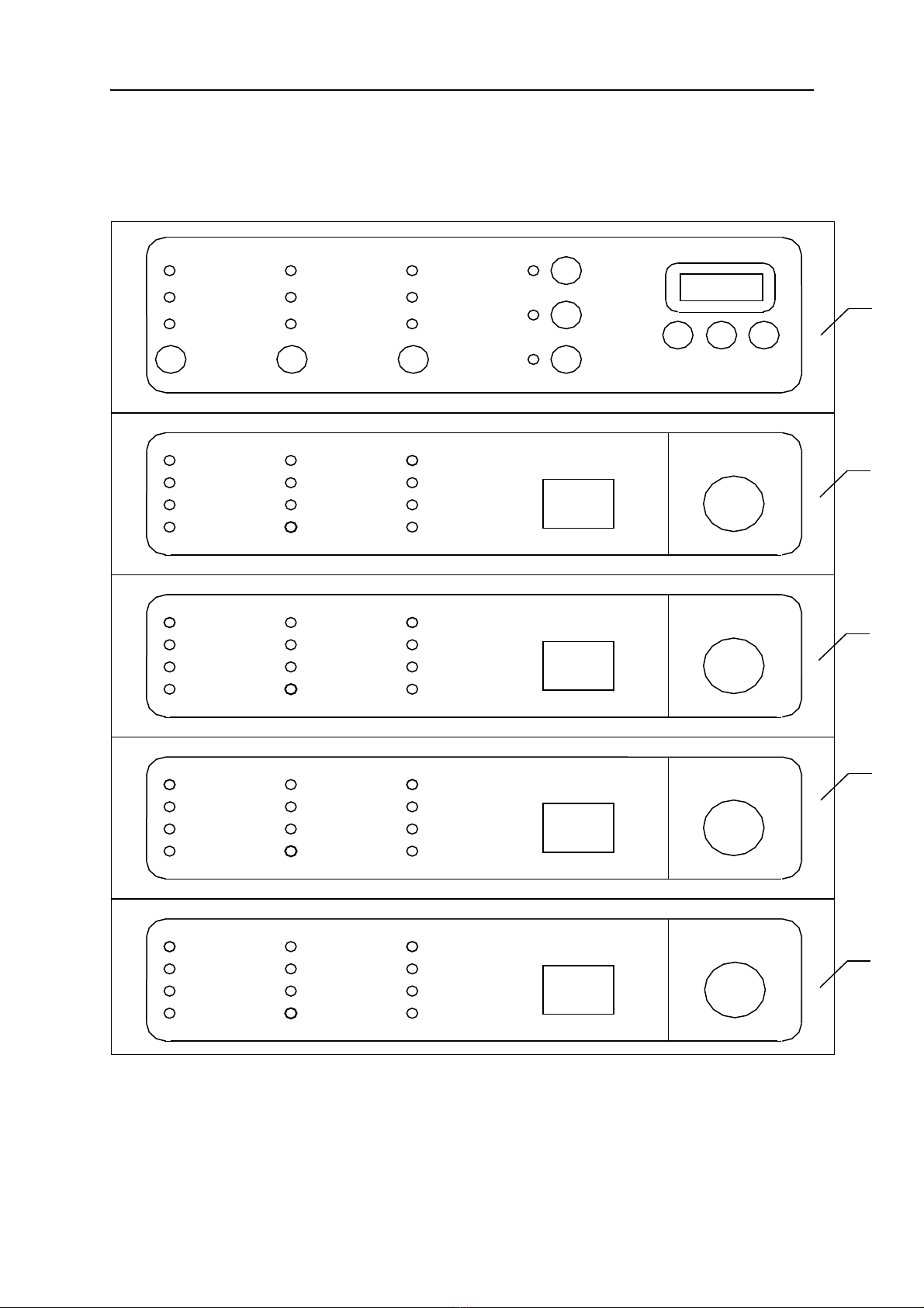
VI.DescriptionoftheKeyboardOperation
Thereare9functionkeysonthemainpanelofJB-QB-QM200/4(showninfigure10);functionsbelow.
KEYON/OFF
Akeyboardlockissetinthesystemtoavoidmis-operation.
Tounlockthekeyboard,pressestheKEYON/OFFonthekeyboard,thenthekeyboardisunlockedand KEY
ON/OFF lightwillbeon.Tolockthekeyboard,presstheKEYON/OFFkeyandthe KEYON/OFF lightwillbeout.
Afterthekeyboardison,withnooperationforover4minutes,thekeyboardwillautomaticallyturnoffandthelight
willgoout.Whenthekeyboardislocked,otherkeysareinvalidexceptSILENCEkey,
SILENCE
Eliminatecurrentaudiblealarmsofthesystem,andthelightwillbeon.Whennewalarmoccurs,itwillgoout.
SYSTEMRESET
Thiskeypressed,thesystemwillclearallalarms,troubles,exitpausestatusandinitializealltheoutputs.
SYSTEMTEST
Pressthiskeytorunasystemself-testing.Duringthetest,alltheindicatorlightsanddelaydigitalclockswillbeon,
thedigitalclockrepeatedlyindicates0-4rapidly,andtheaudiblealarmchangesinthefollowingsequence:trouble
sound →firealarmsound →releasecountdownsound →releasealarmsound.
MANUAL/AUTO
Pressthiskeytoswitchbetweenautomaticandmanualmode.
PAUSE
Thiskeypressed,thesystemwillswitchtothepausemodeandtheindicatorlightwillbeon.
Whenanyareaofthesystemisinreleasedelaystatus,thekeyboardlockdoesn’tlimitthekey.Thatis,whetherthe
keyboardisonoroff,thekeyPAUSEiseffectiveallthetime.Inthiscase,PAUSEpressed,allareasinrelease
delaystatuswillstopcountdownimmediatelyandexitreleasedelaystatus.
Note:Whenthesystemisinthepausemode,itwillsoundonceeveryminutetoprompttheusersthatithaslostthe
functionoffireextinguishing.Thispromptedsoundcan’tbeeliminatedbysilence.
HOUR
Thiskeypressedonce,thehourwillbeincreasedbyone.
MINUTE
Thiskeypressedonce,theminutewillbeincreasedbyone,meanwhile,thesecondwillbesetto0.
QUERY
Thiskeypressedonce,queryreleasestartuptimeofonearea.Thedelaydigitalclockofcorrespondingarea
displaywillshow “CH”,whichmeansit’squeryingreleasestartuptimeofthearea.Thedigitalclockofthemain
displaywillshowreleasestartuptimeoftheareaandwillhavenodisplaywhenthereleasehasn’tstartinthearea.
Itwillautomaticallyrestorenormalstatuswithnooperationin10secs.
JB-QB-QM200/4panelofarean(n=1-4)hasoneemergentreleasekey(seefigure10),functionsbelow:
EMERGENTRELEASE
Topressthisbutton,youmustbreakthecrashswitchonthepanel,andpressheavilyonthecentralpointas
pointedbytheredarrowtotouchtheprotectedmicroswitchandholdfor1-2seconds.Thisbuttonpressed,the
systemwillstarttheelectromagneticvalveafteradelay20secondsandgivesoffaudible/visiblealarm
correspondingly,thenstartcorrespondingoutputsignal.
VII.PowerManagementfortheControlPanel
JB-QB-QM200/4hasadoptedtheadvancedpowermanagementsystemtoguaranteestableandreliable
operationofthesystem.
WhentheACinputisbetweenAC187V-AC242V,theAC-DCpowermodulecanoperateproperly.Atthisstage,
thesystemwilloutputDC24V-DC27.6Vtoensurethattheelectromagneticvalveandotherequipmentswithlow
impedancecanoperateproperlyevenwhenthelinelossisremoved.
WhentheACinputexceedstherangeofAC187V-AC242V,thesystemwillseamlesslyswitchtoDCpower
supplyandalarmforACTROUBLE.Meanwhilethesystemoutputdependsonthevoltageofthebattery.The