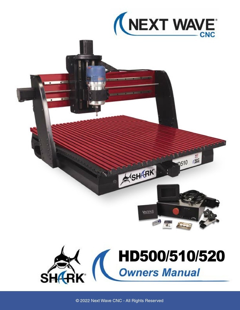
Next Wave CNC SHARK HD500 User manual

SHARK HD500/510/520
User’s Manual
®

2SHARK HD500 Series User’s Manual
Copyright 2020 Next Wave CNC - All Rights Reserved.
SHARK is the registered trademark of Next Wave CNC.
Ready2Control is copyrighted by Next Wave CNC.
Virtual Zero Unlimited is patented by Next Wave CNC.
All other trademarks are the property of their respective owners.
Information in this manual is subject to change without notice.
The most recent version of this manual can be found at
www.NextWaveCNC.com/downloads-links
Next Wave CNC, LLC,
600 W. Boundary St., Perrysburg, Ohio 43551
USA
Main Office Phone (419) 318-4822

3
V. 12/20
To Our Customers ………………………….…………………….… 4
System Requirements ……….………….…………..…..……......... 4
Product Warranty ..….…………….……………………………….… 5
Technical Support …….…………………….……..……………..…. 6
Safety .……….………………………………………..….…………… 7
Machine Assembly ……. ……………………………..….………… 10
Machine Registration …………………………………..….………… 20
VCarve software Installation ………….………..……..….………… 24
VCarve license registration ………….………..………….………… 32
Vectric User Portal account registration ……………..….………… 40
VCarve software version updates …...………..……..…..………… 42
CNC Workflow …..…………………………… ………………..…… 51
Machine Maintenance ………………………..………..….………… 60
Resources ………………………………………..……..…….……… 63
Table of Contents Page
Please read this manual carefully. It provides
important setup and operational information for
your SHARK HD CNC. This manual has been
written with the assumption that you are
experienced with the basic operation of a
computer as well as the technical knowledge
required to safely operate power tools.

4SHARK HD500 Series User’s Manual
To Our Customers
Thank you for purchasing a SHARK HD CNC from Next Wave CNC.
Included with your purchase are software licenses for Ready2Control,
Virtual Zero Unlimited, and VCarve Desktop (with the HD500 and
HD510) or VCarve Pro (with the HD520).
The Ready2Control software runs on your computer and is used to
run your toolpath files and control your SHARK HD CNC. It operates
in a similar way to the LCD Pendant but includes additional machine
control tools. See the Ready2Control User’s Manual for more
information.
Virtual Zero Unlimited allows you to map a curved or uneven
surface using as many reference points as you choose. The program
uses these points to adjust the G-code to conform to the curved or
uneven surface of your material. See the Virtual Zero Unlimited
User’s Manual for more information.
The Vectric VCarve software includes a broad set of CNC project
design and toolpath tools. Design tutorials and software support can
be found at www.vectric.com
System Requirements
All SHARK CNCs use 110v power. Your SHARK HD CNC can be
controlled with the included LCD Control Pendant or the
Ready2Control software.
Ready2Control software can be installed and run on any PC
computer running Windows 10. The computer must also have a USB
output port.
Vectric VCarve will run on most Microsoft Windows based PCs and
does not require any special hardware or graphics card.
NOTE: An Apple computer can be used if it’s running
Microsoft Windows via Parallels or Bootcamp.
Visit Vectric.com for details and exceptions.

5
V. 12/20
Next Wave CNC warrants your new SHARK HD5
series CNC to be free from defects in material
and workmanship for TWO YEARS from the date
of purchase. The warranty applies only to the
original retail purchaser of the SHARK HD5 series
CNC when purchased from an authorized Next
Wave CNC distributor. This warranty covers the
parts and labor to correct the defect. It does not
cover the cost of shipping the machine and/or
parts to Next Wave CNC for evaluation or repair.
Warranty
This warranty does not apply to problems arising from normal wear
and tear, misuse, abuse, negligence, accidents, unauthorized repairs,
alterations, or lack of maintenance. This warranty is void if the SHARK
HD5 CNC or any portion of it is modified without the prior written
permission from Next Wave CNC, or if the machine is located or has
been used outside of the country where the machine was purchased.
Please contact Next Wave CNC to take advantage of this warranty. If
Next Wave CNC determines that your SHARK ® HD5 series CNC is
defective in material or workmanship, Next Wave CNC will at its
expense and upon proof of purchase send replacement parts to the
original retail purchaser necessary to cure the defect. Next Wave
CNC will repair your SHARK HD CNC provided the machine or
affected components are returned to Next Wave CNC, shipping
prepaid, with proof of purchase and within the warranty period.
Next Wave CNC disclaims all other express or implied warranties,
including fitness for a particular purpose. Next Wave CNC shall not be
liable for death, injuries to persons or property, or incidental,
consequential, contingent or special damages arising from the use of
the SHARK HD CNC .
Ready2Control software
Next Wave CNC warrants Ready2Contol and Virtual Zero Unlimited to
perform as intended and will provide customer support to the original
purchaser when purchased from an authorized retail distributor.
Warranty only applies to the current version or the support needed to
update a past version. The cost of the software upgrade (if any) is not
covered by the warranty.
Vectric VCarve software warranty
For details visit: https://www.vectric.com/terms

6SHARK HD500 Series User’s Manual
Serial Number and Software License Information
For easy reference and record keeping, enter your SHARK HD
and Vectric information below. To locate the information, refer
to the pages listed below.
Controller Box Serial Number
(page 21)_______________________________________
LCD Pendant Serial Number
(page 21)_______________________________________
LCD Pendant Unlock Code
(page 22)_______________________________________
Your VCarve User’s Name
(page 35)_______________________________________
VCarve License Code
(page 35)_______________________________________
If you need technical assistance with your SHARK HD
CNC or software, please visit our Support webpage at:
NextWaveCNC.com/support or email Customer Support
at:
Support@NextWaveCNC.com. Please include your
product model number, date of purchase, and other
pertinent information associated with the issue such as
.tap files, VCarve files, screen captures, or photos of your
setup or the problem.
Support Email: support@nextwaveCNC.com
Available: 9 am –5 pm Monday-Friday (Eastern time).
Technical Support

7
V. 12/20
When operating machinery always wear the appropriate ear
and eye protection and follow all safety instructions of the
machine’s owner’s manual and related equipment manuals.
1. Read safety and operating instructions before using your
SHARK CNC.
2. Take time to fully understand how to safely operate your SHARK
CNC.
3. Setup your SHARK CNC following the instructions in this
manual.
4. Always wear appropriate eye and hearing protection when
operating your SHARK CNC and accessories.
5. DO NOT machine metal with your SHARK CNC.
6. Never attempt to adjust the work piece or move the SHARK
while it is running.
7. If needed, use the Cancel or Pause buttons to Stop or Pause
your SHARK CNC during an operation.
8. Never leave your SHARK CNC unattended while it is running.
9. While operating your SHARK CNC, keep a multi-purpose dry
chemical fire extinguisher nearby. It must be rated for both A & C
fires.
10. For added safety and convenience, connect your SHARK CNC
to a 110-115V surge-protected power strip with an on/off switch.
This provides an additional way to turn off the machine in case
of an emergency.
11. Follow all Safety instructions provide with your SHARK CNC and
accessories.
12. Follow all accepted and recommended safety precautions and
practices for woodworking and machining.
Safety

8SHARK HD500 Series User’s Manual
There are four ways that you can immediately stop your SHARK HD
CNC (listed below). Using any of these will immediately stop the
movement of your SHARK HD CNC. They also stop the router if it is
plugged into the Control Box. If you use a Spindle, it can be stop by
pressing the Stop button on the VFD, or if it’s connected to a power
strip, you can turn off the power strip to stop the spindle..
1. The Stop button in the Run screen on the LCD Pendant.
Emergency Stop
2. The Emergency Stop switch on the front of the Control
box

9
V. 12/20
4. The On/Off switch on the surge-protected power strip.
3. The On/Off switch on the back of the Control Box
Emergency Stop (cont.)

10 SHARK HD500 Series User’s Manual
Step 2
Attach the gantry
(see page 13)
Assembly-at-a-glance
ASSEMBLY TIPS
•Use two people to lift the heavy machine base and
gantry parts.
•Lift the machine base by the edges of the aluminum
table or under the front and rear legs.
•During assembly, lift the gantry by the rear beam or
side legs.
•Lift the assembled machine by edges of the aluminum
table or under the front and rear legs.
•DO NOT lift an assembled machine by the side covers
or the gantry.
Step 1
Attach side covers
(see page 12)
Step 3
Attach the cable carrier to the side
of the machine (see page 14)
Machine Assembly
Step 4
Attach the router/spindle mount
and install the router/spindle
(see page 17)

11
V. 12/20
Step 7
Attach power cable to
Control Box.
(see page 19).
Step 6
Attach Pendant to Control Box
(see page 19).
Step 5
Attach motor cables to
back of control box
(see page 18).
IMPORTANT
DO NOT plug in or power up your machine until the motor
and Pendant cables are fully attached.
DO NOT detach or attach motor or Pendant cables when
the Control Box is powered up as this will damage the
electronics and is not covered by the warranty.
MachineAssembly (cont.)

12 SHARK HD500 Series User’s Manual
Step 1a
Rotate side cover sand slide down over the Y-spar.
Step 1b
Attach the side covers with the mounting screws (4 per side). Do not
over-tighten.
Y-spar
Mounting
screws
MachineAssembly (cont.)
Step 1
Attach side covers

13
V. 12/20
MachineAssembly (cont.)
Step 2
Attached Gantry
Attach the gantry to the Y-spar using the included bolts and lock nuts
(6 each side). Do not over-tighten. Attach the gantry using the top six
holes on each leg (as shown above). This is the recommended "low
gantry" position. The bottom two holes can be used if you need to
raise the gantry for additional clearance for tall projects, jigs or
accessories.
Assembly tip –Enlist the help of a neighbor or friend to hold the
gantry in place or add blocks of wood or foam under the gantry beam
to position it during assembly.

14 SHARK HD500 Series User’s Manual
MachineAssembly (cont.)
Step 3a
Use a small tipped screwdriver to gently pry open the latch side of the
crossbars on the cable carrier.
Step 3
Install cable carrier
Step 3b
Loosen the sliding t-nuts that are installed on the cable carrier.

15
V. 12/20
MachineAssembly (cont.)
Step 3c
Remove a few screws from the trim strip at the front left side of the table.
Pull the trim back and slide the t-nuts and the cable carrier into the edge of
the table.
Trim strip
Step 3d
Position the cable carrier inside the left gantry leg.

16 SHARK HD500 Series User’s Manual
MachineAssembly (cont.)
Step 3f
Tighten the screws in the t-nuts to secure the cable carrier to the edge
of the table. Place the cables in the cable carrier and close the
crossbars.
Step 3e
Attach the loose end of the cable carrier to the “Y spar” with the
included bold and nut. (For clarity, the gantry leg is not show in this
picture.

17
V. 12/20
MachineAssembly (cont.)
Step 3g
Re-attached the front trim strip.
Step 4
Install Router/Spindle mount. Loosely attach the mount with the
socket head bolts (included). Insert the router or spindle and tighten
bolts. The height of the router or spindle can be readjusted as
needed for different bits or materials.
An optional 2HP 110v
spindle is available for your
SHARK HD CNC. For
information, contact your
SHARK CNC dealer or visit
www.NextWaveCNC.com

18 SHARK HD500 Series User’s Manual
MachineAssembly (cont.)
Step 5
Attach the motor cables to the back of the control box
Step 5a
Attach the three motor cables and the two homing (RCA) connectors
to the corresponding ports on the back of the control box. The two
round connectors are not specific and can be inserted into either
socket.
Step 5b
Attach the router motor cable and power cables to the back of the
control.
Router power cable Control box power cable
NOTE: If you have the Spindle kit, DO NOT attach the VFD power
cable to the back of the control box. It must be plugged directly into a
wall socket or the power strip.

19
V. 12/20
MachineAssembly (cont.)
Step 6
Attach the pendant cable between the
Pendant and the control box.
Step 7
Plug power cord into the switched surge-protected power strip
to protect your tool and provide another method for shutting
off the machine in case of an emergency.
IMPORTANT –Only plug in and turn on the power AFTER
the all the motor cables have been attached. DO NOT
attach or detach motor cables when the control box is
powered up as this will damage the electronics and is not
covered by the warranty.

20 SHARK HD500 Series User’s Manual
Emergency Switch
Registering your SHARK HD CNC
Step 1
Power up your SHARK HD CNC by turning on both the main power
switch and the Emergency switch. During general use, you only need
to turn off one of these switches to cut power to the machine.
Step 2
Once you power up your SHARK HD CNC, the opening screen will
appear on the pendant. Click Continue.
Main power Switch
IMPORTANT. Always turn off the power switch(s) when connecting or
disconnecting any of the cables. Failure to do so can cause damage to
electrical components and is not covered by the warranty.
Other manuals for SHARK HD500
1
This manual suits for next models
3
Table of contents
Other Next Wave CNC Control System manuals
Popular Control System manuals by other brands

Radionics
Radionics D9124 Operation and installation manual
ECOFOREST
ECOFOREST ecoSMART e-source USER, INSTALLER AND TECHNICAL SERVICE MANUAL

Mi-Light
Mi-Light LS3 User instruction
micro-trak
micro-trak MT-3000 Reference manual
Toshiba
Toshiba TOSDIC-CIE DS Installation and wiring manual
SYR
SYR BA-Filling-Combi 6628 Instructions for use and installation
